
Aspire E360 User Guide EN
Page 16
... or diskette. You can also press the volume control/mute knob on your USB keyboard to toggle from the computer. If your drive cannot read diskette, hard disk, CD or DVD information. Q: System cannot write data on the icon and deselect the Mute option. A: Check the following...: • Make sure the diskette or hard disk is not write-protected. • Make sure that you are using a good (i.e., undamaged) disk. A: Check the following: • The volume may...
... or diskette. You can also press the volume control/mute knob on your USB keyboard to toggle from the computer. If your drive cannot read diskette, hard disk, CD or DVD information. Q: System cannot write data on the icon and deselect the Mute option. A: Check the following...: • Make sure the diskette or hard disk is not write-protected. • Make sure that you are using a good (i.e., undamaged) disk. A: Check the following: • The volume may...

Aspire E650 Service Guide
Page 9
... Chapter 3 Machine Disassembly and Replacement 48 General Information 49 Before You Begin 49 Aspire E650 Disassembly Procedure 50 Opening the Computer 50 Removing the Optical Disk Drive 52 Removing the Card Reader and the Floppy Disk Drive 52 Removing the Hard Disk Drive 53 Removing the Add-on Cards 54 Removing the Power Supply 55 Removing...
... Chapter 3 Machine Disassembly and Replacement 48 General Information 49 Before You Begin 49 Aspire E650 Disassembly Procedure 50 Opening the Computer 50 Removing the Optical Disk Drive 52 Removing the Card Reader and the Floppy Disk Drive 52 Removing the Hard Disk Drive 53 Removing the Add-on Cards 54 Removing the Power Supply 55 Removing...

Aspire E650 Service Guide
Page 20
..., select Recovery settings and click Next. 5. Create factory default image CD 4. Press + to open the Acer eRecovery utility. 3. Restore from hard drive, CD, or DVD. Press + to open the Acer eRecovery utility. 3. Select the backup method: • Use Backup to HDD to store the backup disc ...image on screen to create backup. 1. In the Acer eRecovery window, select Recovery actions and click Next. 5. Acer eRecovery consists of the current system configuration to hard drive, CD, or DVD. Then follow the steps below to store the backup disc ...
..., select Recovery settings and click Next. 5. Create factory default image CD 4. Press + to open the Acer eRecovery utility. 3. Restore from hard drive, CD, or DVD. Press + to open the Acer eRecovery utility. 3. Select the backup method: • Use Backup to HDD to store the backup disc ...image on screen to create backup. 1. In the Acer eRecovery window, select Recovery actions and click Next. 5. Acer eRecovery consists of the current system configuration to hard drive, CD, or DVD. Then follow the steps below to store the backup disc ...

Aspire E650 Service Guide
Page 30
...Windows). T CPU asserts STPCLK# and goes into power saving mode. T Resume method: device activated (keyboard for DOS, keyboard & mouse for hard disk drive devices (zero to 15 minutes, time step = one minute). T Disable H-sync and V-sync signals to five seconds. T Resume method: ... specification 1.0b S0, S1, S3 and S5 sleep state support Onboard device power management support Onboard device configuration support 20 Chapter 1 T Hard disk drive goes into Standby mode (for ATA standard interface). T Resume recovery time: seven to control the VESA DPMS monitor. T LED on the...
...Windows). T CPU asserts STPCLK# and goes into power saving mode. T Resume method: device activated (keyboard for DOS, keyboard & mouse for hard disk drive devices (zero to 15 minutes, time step = one minute). T Disable H-sync and V-sync signals to five seconds. T Resume method: ... specification 1.0b S0, S1, S3 and S5 sleep state support Onboard device power management support Onboard device configuration support 20 Chapter 1 T Hard disk drive goes into Standby mode (for ATA standard interface). T Resume recovery time: seven to control the VESA DPMS monitor. T LED on the...

Aspire E650 Service Guide
Page 31
... appear: Press DEL to enter SETUP Press the delete key to enter the BIOS Setup Utility. The BIOS Setup Utility enables you to configure: • Hard drives, diskette drives and peripherals • Video display type and display options • Password protection from unauthorized use • Power management features The settings made in the...
... appear: Press DEL to enter SETUP Press the delete key to enter the BIOS Setup Utility. The BIOS Setup Utility enables you to configure: • Hard drives, diskette drives and peripherals • Video display type and display options • Password protection from unauthorized use • Power management features The settings made in the...

Aspire E650 Service Guide
Page 34
... are running a Windows OS, these items are automatically updated whenever you make changes to Serial ATA (Advanced Technology Attachment), the standard interface for the IDE hard drives which are currently used in most PCs. 24 Chapter 2 IDE Devices Your computer has one IDE channel and can be installed with one or two... set on the IDE channel. Use this item to configure each device on the computer. This main board features four SATA connectors supporting four SATA drives.
... are running a Windows OS, these items are automatically updated whenever you make changes to Serial ATA (Advanced Technology Attachment), the standard interface for the IDE hard drives which are currently used in most PCs. 24 Chapter 2 IDE Devices Your computer has one IDE channel and can be installed with one or two... set on the IDE channel. Use this item to configure each device on the computer. This main board features four SATA connectors supporting four SATA drives.

Aspire E650 Service Guide
Page 35
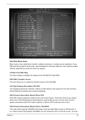
... appear in the items described below. Chapter 2 25 Choose the line that can connect one line will automatically decide the fastest way to access the hard disk drive. If you choose IDE channel 2/3 Master, the item may change the value to Manual and then manually configure the... to the system. Please note that supports LBA mode, more than one or two diskette drives. If it fails to find a device, change to Extended IDE drive. You can be used to access IDE hard disks such as LBA (Large Blocking Addressing). IDE HDD Auto-Detection Press while this item Auto to enable...
... appear in the items described below. Chapter 2 25 Choose the line that can connect one line will automatically decide the fastest way to access the hard disk drive. If you choose IDE channel 2/3 Master, the item may change the value to Manual and then manually configure the... to the system. Please note that supports LBA mode, more than one or two diskette drives. If it fails to find a device, change to Extended IDE drive. You can be used to access IDE hard disks such as LBA (Large Blocking Addressing). IDE HDD Auto-Detection Press while this item Auto to enable...
Aspire E650 Service Guide
Page 45
...let the system auto detect which provides faster access to Auto. IDE HDD Block Mode Block mode is used by IDE devices. If your IDE hard drive supports block mode, select Enabled for two IDE channels. If you install a device that supports UltraDMA, you to enable the transfer access of... PIO (Programmed Input/Output) is also called block transfer, multiple commands, or multiple sector read /write per sector the drive can change the item on this list to IDE devices. IDE DMA Transfer Access This item allows you can support. IDE Primary/Secondary Master/...
...let the system auto detect which provides faster access to Auto. IDE HDD Block Mode Block mode is used by IDE devices. If your IDE hard drive supports block mode, select Enabled for two IDE channels. If you install a device that supports UltraDMA, you to enable the transfer access of... PIO (Programmed Input/Output) is also called block transfer, multiple commands, or multiple sector read /write per sector the drive can change the item on this list to IDE devices. IDE DMA Transfer Access This item allows you can support. IDE Primary/Secondary Master/...

Aspire E650 Service Guide
Page 63
Disconnect the power cable. 3. Slide the rails. 5. Pull the hard disk drive holder in the direction of arrow. 53 Chapter 3 Disconnect the SATA cable. 2. Removing the Hard Disk Drive 1. Disconnect the SATA cable linked on the main board. 4.
Disconnect the power cable. 3. Slide the rails. 5. Pull the hard disk drive holder in the direction of arrow. 53 Chapter 3 Disconnect the SATA cable. 2. Removing the Hard Disk Drive 1. Disconnect the SATA cable linked on the main board. 4.

Aspire E650 Service Guide
Page 75
...message waiting indication. After receiving a power on / off signal, at least 50 ms to signal the power supply to the SATA (hard drive activity LED) connectors. The switch should maintain contact for at least two seconds elapse before the power supply recognizes another on or off ...function requires the connection of the IDE hard drive. Chapter 5 65 The time requirement is closed, the board resets and runs POST. Pin Signal Name 1 HDD_LED_P 3 HDD_LED_N 5 RST_SW_N...
...message waiting indication. After receiving a power on / off signal, at least 50 ms to signal the power supply to the SATA (hard drive activity LED) connectors. The switch should maintain contact for at least two seconds elapse before the power supply recognizes another on or off ...function requires the connection of the IDE hard drive. Chapter 5 65 The time requirement is closed, the board resets and runs POST. Pin Signal Name 1 HDD_LED_P 3 HDD_LED_N 5 RST_SW_N...

Aspire E650 Service Guide
Page 76
... two IDE devices by one cable, ensure that one orientation. SATA refers to Serial ATA (Advanced Technology Attachment) is the standard interface for the IDE hard drives which are well designed and will only fit in most PCs. The FDD connector is used in one device is set as Master and the... other end of the cable connects to the FDD drive. IDE Connector The main board supports four high data transfer SATA ports with each runs up the hard drives on Card Slots PCIE x16 slot The PCI Express x16 slot is fully compliant to the...
... two IDE devices by one cable, ensure that one orientation. SATA refers to Serial ATA (Advanced Technology Attachment) is the standard interface for the IDE hard drives which are well designed and will only fit in most PCs. The FDD connector is used in one device is set as Master and the... other end of the cable connects to the FDD drive. IDE Connector The main board supports four high data transfer SATA ports with each runs up the hard drives on Card Slots PCIE x16 slot The PCI Express x16 slot is fully compliant to the...


