Aspire 8930G Service Guide
Page 16
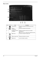
Note: Do not cover or obstruct the opening of the fan. Ventilation slots and cooling fan Battery bay Enable the computer to stay cool, even after prolonged use. Houses the computer's battery pack. 5 Battery release latch Releases the battery for removal. 6 Battery lock Locks the battery in position. 10 Chapter 1 Base view No. 1 2 3 4 Icon Item Hard disk bay Description Houses the computer's hard disk (secured with screws). Memory compartment Houses the computer's main memory.
Note: Do not cover or obstruct the opening of the fan. Ventilation slots and cooling fan Battery bay Enable the computer to stay cool, even after prolonged use. Houses the computer's battery pack. 5 Battery release latch Releases the battery for removal. 6 Battery lock Locks the battery in position. 10 Chapter 1 Base view No. 1 2 3 4 Icon Item Hard disk bay Description Houses the computer's hard disk (secured with screws). Memory compartment Houses the computer's main memory.

Aspire 8930G Service Guide
Page 58
Removing the Wireless Cover & RAM Module 3. Pop out the memory module from the notebook. Remove the wireless antenna and remove the wireless screws then remove the wireless card. 4. Remove the six screws fastening the CTO cover. 2. Detach the CTO cover from the DIMM socket then remove it (If the notebook has two memory modules, then repeat this step). 52 Chapter 3 Removing the HDD/Memory Module/Wireless LAN Card/TV Tuner Card/System Fan/Thermal Modules/CPU Removing the HDD 1.
Removing the Wireless Cover & RAM Module 3. Pop out the memory module from the notebook. Remove the wireless antenna and remove the wireless screws then remove the wireless card. 4. Remove the six screws fastening the CTO cover. 2. Detach the CTO cover from the DIMM socket then remove it (If the notebook has two memory modules, then repeat this step). 52 Chapter 3 Removing the HDD/Memory Module/Wireless LAN Card/TV Tuner Card/System Fan/Thermal Modules/CPU Removing the HDD 1.

Aspire 8930G Service Guide
Page 59
Disconnect the main and auxiliary antennae from the machine. 8. Remove the TV card from the TV card. 6. Removing the Wireless LAN Card/TV Tunder Card and System Fan 5. Loose two screws from the machine. 10. Loose the FAN screw. Remove FAN cable from the TV card. 7. Chapter 3 53 Remove HDD module as shown. 9.
Disconnect the main and auxiliary antennae from the machine. 8. Remove the TV card from the TV card. 6. Removing the Wireless LAN Card/TV Tunder Card and System Fan 5. Loose two screws from the machine. 10. Loose the FAN screw. Remove FAN cable from the TV card. 7. Chapter 3 53 Remove HDD module as shown. 9.

Aspire 8930G Service Guide
Page 60
11. Removing the Thermal Modules and the CPU 12. Then take out the CPU heatsink from the main unit as shown. Take out the system fan from the main board. 15. Remove the Express dummy card. 54 Chapter 3 Remove the two screws holding the finger heatsink. 13. Use a flat screwdriver to release the CPU lock (Turn counter clock-wise) then remove the CPU carefully. 16. Detach the finger heatsink from the main board. 14.
11. Removing the Thermal Modules and the CPU 12. Then take out the CPU heatsink from the main unit as shown. Take out the system fan from the main board. 15. Remove the Express dummy card. 54 Chapter 3 Remove the two screws holding the finger heatsink. 13. Use a flat screwdriver to release the CPU lock (Turn counter clock-wise) then remove the CPU carefully. 16. Detach the finger heatsink from the main board. 14.

Aspire 8930G Service Guide
Page 112
...KO.0020E.002 KU.00805.044 KU.0080E.017 KU.0080F.001 Part Name and Description FAN Acer Part No. 23.AP50N.001 106 Chapter 6 CPU/PROCESSOR Category DVD RW DRIVE Category FAN Category Part Name and Description CPU INTEL CORE2DUAL P7350 PGA 2.0G 3M 1066 25W CPU INTEL...53G 6M 1066 25W CPU INTEL CORE2DUAL T9400 PGA 2.53G 6M 1066 35W CPU INTEL CORE2DUAL T9600 PGA 2.8G 6M 1066 35W Acer Part No. KC.73501.DPP KC.84001.DPP KC.86001.DPP KC.95001.DPP KC.94001.DTP KC.96001.DTP Part Name ...7580S LF W/O BEZEL SATA ODD PLDS SUPER-MULTI DRIVE 12.7MM TRAY DL 8X DS-8A2S LF W/O BEZEL SATA Acer Part No.
...KO.0020E.002 KU.00805.044 KU.0080E.017 KU.0080F.001 Part Name and Description FAN Acer Part No. 23.AP50N.001 106 Chapter 6 CPU/PROCESSOR Category DVD RW DRIVE Category FAN Category Part Name and Description CPU INTEL CORE2DUAL P7350 PGA 2.0G 3M 1066 25W CPU INTEL...53G 6M 1066 25W CPU INTEL CORE2DUAL T9400 PGA 2.53G 6M 1066 35W CPU INTEL CORE2DUAL T9600 PGA 2.8G 6M 1066 35W Acer Part No. KC.73501.DPP KC.84001.DPP KC.86001.DPP KC.95001.DPP KC.94001.DTP KC.96001.DTP Part Name ...7580S LF W/O BEZEL SATA ODD PLDS SUPER-MULTI DRIVE 12.7MM TRAY DL 8X DS-8A2S LF W/O BEZEL SATA Acer Part No.

Aspire 8930G/8930Q Quick Guide
Page 9
Note: Do not cover or obstruct the opening of the fan. 4 Battery bay Houses the computer's battery pack. 5 Battery release latch Releases the battery for removal. 6 Battery lock Locks the battery in position. 9 Base view English # Icon Item Description 1 Hard disk bay Houses the computer's hard disk (secured with screws). 2 Memory compartment Houses the computer's main memory. 3 Ventilation slots and Enable the computer to stay cool, even after cooling fan prolonged use.
Note: Do not cover or obstruct the opening of the fan. 4 Battery bay Houses the computer's battery pack. 5 Battery release latch Releases the battery for removal. 6 Battery lock Locks the battery in position. 9 Base view English # Icon Item Description 1 Hard disk bay Houses the computer's hard disk (secured with screws). 2 Memory compartment Houses the computer's main memory. 3 Ventilation slots and Enable the computer to stay cool, even after cooling fan prolonged use.


