Service Guide
Page 3
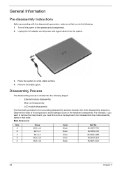
... of the hardware components. Main Screw List Item A B C D E Screw M2.5 x L5 M2 x L3 M3 x L4 M2.5 x L4 M2.5 x L6 Color Black Black Silver Silver Black Part No. 86.00F87.735 86.00F80.723 86.9A524.4R0 86.00H36.534 86.00E12.536 28 Chapter 3 Place the system on a flat, stable surface...
... of the hardware components. Main Screw List Item A B C D E Screw M2.5 x L5 M2 x L3 M3 x L4 M2.5 x L4 M2.5 x L6 Color Black Black Silver Silver Black Part No. 86.00F87.735 86.00F80.723 86.9A524.4R0 86.00H36.534 86.00E12.536 28 Chapter 3 Place the system on a flat, stable surface...
Service Guide
Page 4
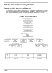
For example, if you want to be removed during servicing. External Module Disassembly Process External Modules Disassembly Flowchart The flowchart below gives you a graphic representation on the entire disassembly sequence and instructs you must first remove the keyboard, then disassemble the inside assembly frame in that need to remove the main board, you on the components that order. Item B C E Screw M2 x L3 M3 x L4 M2.5 x L6 Color Black Silver Black Part No. 86.00F80.723 86.9A524.4R0 86.00E12.536 Chapter 3 29
For example, if you want to be removed during servicing. External Module Disassembly Process External Modules Disassembly Flowchart The flowchart below gives you a graphic representation on the entire disassembly sequence and instructs you must first remove the keyboard, then disassemble the inside assembly frame in that need to remove the main board, you on the components that order. Item B C E Screw M2 x L3 M3 x L4 M2.5 x L6 Color Black Silver Black Part No. 86.00F80.723 86.9A524.4R0 86.00E12.536 Chapter 3 29
Service Guide
Page 9
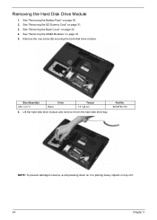
See "Removing the SD Dummy Card" on top of it. 34 Chapter 3 Size (Quantity) M2 x L3 (1) Black Color Torque 1.6 kgf-cm 6. Lift the hard disk drive module and remove it or placing heavy objects on page 31. 3. Part No. 86.00F80.723 NOTE: To prevent damage to device, avoid pressing down on it from the hard disk drive bay. See "Removing the Battery Pack" on page 33 5. Remove the one screw (B) securing the hard disk drive module. See "Removing the DIMM Modules" on page 30. 2. See "Removing the Back Cover" on page 32. 4. Removing the Hard Disk Drive Module 1.
See "Removing the SD Dummy Card" on top of it. 34 Chapter 3 Size (Quantity) M2 x L3 (1) Black Color Torque 1.6 kgf-cm 6. Lift the hard disk drive module and remove it or placing heavy objects on page 31. 3. Part No. 86.00F80.723 NOTE: To prevent damage to device, avoid pressing down on it from the hard disk drive bay. See "Removing the Battery Pack" on page 33 5. Remove the one screw (B) securing the hard disk drive module. See "Removing the DIMM Modules" on page 30. 2. See "Removing the Back Cover" on page 32. 4. Removing the Hard Disk Drive Module 1.
Service Guide
Page 10
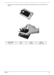
Size (Quantity) M3 x L4 (1) Color Silver Torque 3.0 kgf-cm Part No. 86.9A524.4R0 Chapter 3 35 7. Remove the two screws (C) securing the hard disk to the bracket and remove the hard disk from the bracket.
Size (Quantity) M3 x L4 (1) Color Silver Torque 3.0 kgf-cm Part No. 86.9A524.4R0 Chapter 3 35 7. Remove the two screws (C) securing the hard disk to the bracket and remove the hard disk from the bracket.
Service Guide
Page 11
... antenna cable from AUX connector and the yellow antenna cable from Main connector on page 31. 3. Size (Quantity) M2 x L3 (1) Color Black Torque 1.6 kgf-cm Part No. 86.00F80.723 7. See "Removing the Back Cover" on page 34. 6. See "Removing the Hard Disk Drive Module" on page 32. 4. See "Removing the...
... antenna cable from AUX connector and the yellow antenna cable from Main connector on page 31. 3. Size (Quantity) M2 x L3 (1) Color Black Torque 1.6 kgf-cm Part No. 86.00F80.723 7. See "Removing the Back Cover" on page 34. 6. See "Removing the Hard Disk Drive Module" on page 32. 4. See "Removing the...

Service Guide
Page 13
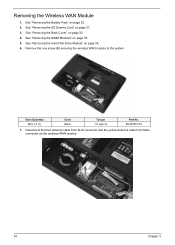
Size (Quantity) M2 x L3 (1) Color Black Torque 1.6 kgf-cm Part No. 86.00F80.723 9. Disconnect the black antenna cable from MAIN connector and the white antenna cable from AUX connector on the WLAN module. 38 Chapter 3 8. Remove the one screw (B) securing the WLAN module to the system.
Size (Quantity) M2 x L3 (1) Color Black Torque 1.6 kgf-cm Part No. 86.00F80.723 9. Disconnect the black antenna cable from MAIN connector and the white antenna cable from AUX connector on the WLAN module. 38 Chapter 3 8. Remove the one screw (B) securing the WLAN module to the system.
Service Guide
Page 14
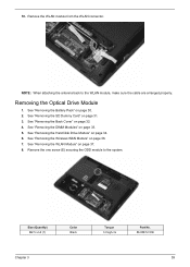
... the Wireless WAN Module" on page 31. 3. Remove the WLAN module from the WLAN connector. Size (Quantity) M2.5 x L6 (1) Color Black Chapter 3 Torque 3.0 kgf-cm Part No. 86.00E12.536 39 See "Removing the Hard Disk Drive Module" on page 34. 6. 10.
... the Wireless WAN Module" on page 31. 3. Remove the WLAN module from the WLAN connector. Size (Quantity) M2.5 x L6 (1) Color Black Chapter 3 Torque 3.0 kgf-cm Part No. 86.00E12.536 39 See "Removing the Hard Disk Drive Module" on page 34. 6. 10.

Service Guide
Page 15
9. Size (Quantity) M2 x L3 (1) Color Black Torque 1.6 kgf-cm Part No. 86.00F80.723 40 Chapter 3 Slowly pull out the ODD module from the ODD drive bay. 10. Remove the one screw (B) securing the ODD bracket to the ODD module.
9. Size (Quantity) M2 x L3 (1) Color Black Torque 1.6 kgf-cm Part No. 86.00F80.723 40 Chapter 3 Slowly pull out the ODD module from the ODD drive bay. 10. Remove the one screw (B) securing the ODD bracket to the ODD module.
Service Guide
Page 19
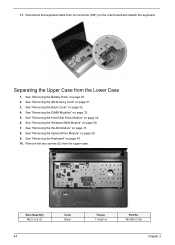
... the Optical Drive Module" on page 32. 4. See "Removing the DIMM Modules" on page 34. 6. Size (Quantity) M2.5 x L6 (2) 44 Color Black Torque 1.6 kgf-cm Part No. 86.00E12.536 Chapter 3 Separating the Upper Case from the upper case. 11. Remove the two screws (E) from the Lower Case 1. See "Removing the...
... the Optical Drive Module" on page 32. 4. See "Removing the DIMM Modules" on page 34. 6. Size (Quantity) M2.5 x L6 (2) 44 Color Black Torque 1.6 kgf-cm Part No. 86.00E12.536 Chapter 3 Separating the Upper Case from the upper case. 11. Remove the two screws (E) from the Lower Case 1. See "Removing the...
Service Guide
Page 24
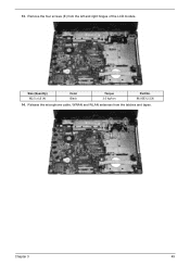
13. Release the microphone cable, WWAN and WLAN antennas from the left and right hinges of the LCD module. Size (Quantity) M2.5 x L6 (4) Color Black Torque 3.0 kgf-cm Part No. 86.00E12.536 14. Chapter 3 49 Remove the four screws (E) from the latches and tapes.
13. Release the microphone cable, WWAN and WLAN antennas from the left and right hinges of the LCD module. Size (Quantity) M2.5 x L6 (4) Color Black Torque 3.0 kgf-cm Part No. 86.00E12.536 14. Chapter 3 49 Remove the four screws (E) from the latches and tapes.
Service Guide
Page 27
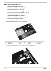
.... 52 Chapter 3 Removing the Power Board 1. See "Removing the Hard Disk Drive Module" on page 32. 4. Size (Quantity) M2 x L3 (1) Color Black Torque 1. 6 kgf-cm Part No. 86.00F80.723 12. See "Removing the Back Cover" on page 34. 6.
.... 52 Chapter 3 Removing the Power Board 1. See "Removing the Hard Disk Drive Module" on page 32. 4. Size (Quantity) M2 x L3 (1) Color Black Torque 1. 6 kgf-cm Part No. 86.00F80.723 12. See "Removing the Back Cover" on page 34. 6.
Service Guide
Page 32
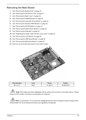
..." on page 33. 5. Remove one screw (B) securing the main board in the figure above image shows. Size (Quantity) M2 x L3 (1) Color Black Torque 1.6 kgf-cm Part No. 86.00F80.723 Note: RTC battery has been highlighted with the yellow rectangle as shown in place. See "Removing the DIMM Modules" on page...
..." on page 33. 5. Remove one screw (B) securing the main board in the figure above image shows. Size (Quantity) M2 x L3 (1) Color Black Torque 1.6 kgf-cm Part No. 86.00F80.723 Note: RTC battery has been highlighted with the yellow rectangle as shown in place. See "Removing the DIMM Modules" on page...
Service Guide
Page 40
See "Removing the Battery Pack" on page 43. 10. Size (Quantity) M2.5 x L5 Chapter 3 Color Torque 3.0 kgf-cm Part No. 86.00F87.735 65 See "Removing the Keyboard" on page 30. 2. See "Separating the Upper Case from the LCD module as shown. See "Removing ...
See "Removing the Battery Pack" on page 43. 10. Size (Quantity) M2.5 x L5 Chapter 3 Color Torque 3.0 kgf-cm Part No. 86.00F87.735 65 See "Removing the Keyboard" on page 30. 2. See "Separating the Upper Case from the LCD module as shown. See "Removing ...

Service Guide
Page 43
... the LCD back cover. See "Separating the Upper Case from the Lower Case" on page 34. 6. Size (Quantity) M2.5 x L4 (6) Color Silver Torque 3.0 kgf-cm Part No. 86.00H36.534 68 Chapter 3 See "Removing the Hard Disk Drive Module" on page 44. 11. See "Removing the LCD Module" on page 30...
... the LCD back cover. See "Separating the Upper Case from the Lower Case" on page 34. 6. Size (Quantity) M2.5 x L4 (6) Color Silver Torque 3.0 kgf-cm Part No. 86.00H36.534 68 Chapter 3 See "Removing the Hard Disk Drive Module" on page 44. 11. See "Removing the LCD Module" on page 30...

Service Guide
Page 45
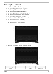
Remove the four screws (B) securing the left and right LCD brackets to remove the brackets. 15. Size (Quantity) M2 x L3 (4) Color Black Torque 1.6 kgf-cm Part No. 86.00F80.723 70 Chapter 3
Remove the four screws (B) securing the left and right LCD brackets to remove the brackets. 15. Size (Quantity) M2 x L3 (4) Color Black Torque 1.6 kgf-cm Part No. 86.00F80.723 70 Chapter 3


