Aspire 7560, 7560G Service Guide
Page 9
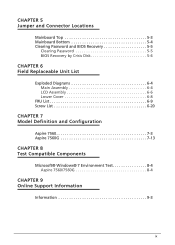
CHAPTER 5 Jumper and Connector Locations Mainboard Top 5-3 Mainboard Bottom 5-4 Clearing Password and BIOS Recovery 5-5 Clearing Password 5-5 BIOS Recovery by Crisis Disk 5-6 CHAPTER 6 Field Replaceable Unit List Exploded Diagrams 6-4 Main Assembly 6-4 LCD Assembly 6-6 Lower Cover 6-8 FRU List 6-9 Screw List 6-20 CHAPTER 7 Model Definition and Configuration Aspire 7560 7-3 Aspire 7560G 7-13 CHAPTER 8 Test Compatible Components Microsoft® Windows® 7 Environment Test 8-4 Aspire 7560/7560G 8-4 CHAPTER 9 Online Support Information Information 9-3 ix
CHAPTER 5 Jumper and Connector Locations Mainboard Top 5-3 Mainboard Bottom 5-4 Clearing Password and BIOS Recovery 5-5 Clearing Password 5-5 BIOS Recovery by Crisis Disk 5-6 CHAPTER 6 Field Replaceable Unit List Exploded Diagrams 6-4 Main Assembly 6-4 LCD Assembly 6-6 Lower Cover 6-8 FRU List 6-9 Screw List 6-20 CHAPTER 7 Model Definition and Configuration Aspire 7560 7-3 Aspire 7560G 7-13 CHAPTER 8 Test Compatible Components Microsoft® Windows® 7 Environment Test 8-4 Aspire 7560/7560G 8-4 CHAPTER 9 Online Support Information Information 9-3 ix
Aspire 7560, 7560G Service Guide
Page 64
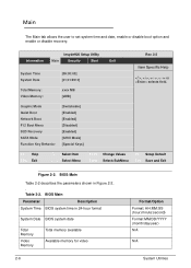
... Main 0 The Main tab allows the user to set system time and date, enable or disable boot option and enable or disable recovery. BIOS Main Parameter Description System Time BIOS system time in Figure 2-2. . InsydeH20 Setup Utility Information Main Security Boot Exit System Time System... [01/01/2010] xxxx MB [xMB] Rev. 3.5 Item Specific Help or selects field. Graphic Mode Quiet Boot Network Boot F12 Boot Menu D2D Recovery SATA Mode Function Key Behavior [Switchable] [Enabled] [Enabled] [Disabled] [Enabled] [AHCI Mode] [Special Keys] F1 Help ESC Exit ...
... Main 0 The Main tab allows the user to set system time and date, enable or disable boot option and enable or disable recovery. BIOS Main Parameter Description System Time BIOS system time in Figure 2-2. . InsydeH20 Setup Utility Information Main Security Boot Exit System Time System... [01/01/2010] xxxx MB [xMB] Rev. 3.5 Item Specific Help or selects field. Graphic Mode Quiet Boot Network Boot F12 Boot Menu D2D Recovery SATA Mode Function Key Behavior [Switchable] [Enabled] [Enabled] [Disabled] [Enabled] [AHCI Mode] [Special Keys] F1 Help ESC Exit ...
Aspire 7560, 7560G Service Guide
Page 65
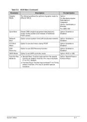
... system from LAN (local area network) Option: Enabled or Disabled F12 Boot Menu Option to use boot menu during POST Option: Enabled or Disabled D2D Recovery Option to use D2D Recovery function Option: Enabled or Disabled SATA Mode Option to F12 by default. Hold the key to perform special functions.
... system from LAN (local area network) Option: Enabled or Disabled F12 Boot Menu Option to use boot menu during POST Option: Enabled or Disabled D2D Recovery Option to use D2D Recovery function Option: Enabled or Disabled SATA Mode Option to F12 by default. Hold the key to perform special functions.
Aspire 7560, 7560G Service Guide
Page 66
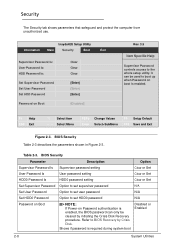
... up when Password on Boot Clear Clear Clear [Enter] [Enter] [Enter] [Disabled] Rev. 3.5 Item Specific Help Supervisor Password controls access to BIOS Recovery by initiating the Crisis Disk Recovery procedure. Table 2-3. InsydeH20 Setup Utility Information Main Security Boot Exit Supervisor Password Is: User Password Is: HDD Password Is: Set Supervisor Password Set...
... up when Password on Boot Clear Clear Clear [Enter] [Enter] [Enter] [Disabled] Rev. 3.5 Item Specific Help Supervisor Password controls access to BIOS Recovery by initiating the Crisis Disk Recovery procedure. Table 2-3. InsydeH20 Setup Utility Information Main Security Boot Exit Supervisor Password Is: User Password Is: HDD Password Is: Set Supervisor Password Set...
Aspire 7560, 7560G Service Guide
Page 73
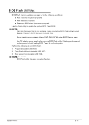
... Flash utility has auto execution function. Refer to bootable USB HDD. 3. Boot system from bootable USB HDD. Copy Flash utilities to Chapter 5, BIOS Recovery by Crisis Disk. If battery pack does not contain power to update the system BIOS Flash ROM. Prepare a bootable USB HDD. 2. BIOS Flash... Utilities 0 BIOS Flash memory updates are required for the following to run BIOS Flash. 1. System Utilities 2-15 NOTE: NOTE: If a Crisis Recovery Disc is not available, create one before BIOS Flash utility is used . Use the Flash utility to finish loading BIOS Flash, do not boot system...
... Flash utility has auto execution function. Refer to bootable USB HDD. 3. Boot system from bootable USB HDD. Copy Flash utilities to Chapter 5, BIOS Recovery by Crisis Disk. If battery pack does not contain power to update the system BIOS Flash ROM. Prepare a bootable USB HDD. 2. BIOS Flash... Utilities 0 BIOS Flash memory updates are required for the following to run BIOS Flash. 1. System Utilities 2-15 NOTE: NOTE: If a Crisis Recovery Disc is not available, create one before BIOS Flash utility is used . Use the Flash utility to finish loading BIOS Flash, do not boot system...
Aspire 7560, 7560G Service Guide
Page 79
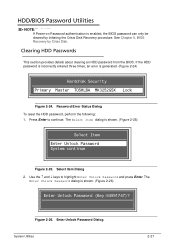
... Press Enter to highlight Enter Unlock Password and press Enter. Password Error Status Dialog To reset the HDD password, perform the following: 1. See Chapter 5, BIOS Recovery by initiating the Crisis Disk Recovery procedure. Use the and keys to continue.
... Press Enter to highlight Enter Unlock Password and press Enter. Password Error Status Dialog To reset the HDD password, perform the following: 1. See Chapter 5, BIOS Recovery by initiating the Crisis Disk Recovery procedure. Use the and keys to continue.

Aspire 7560, 7560G Service Guide
Page 179
.... (Refer to enter the BIOS Utility. Troubleshooting 4-19 Insert the Windows Vista Operating System DVD in the ODD and restart the computer. When the System Recovery Options screen appears, click Next. When complete, click Finish. Restart the computer and press F2 to Maintenance Flowchart) Mainboard 0 To determine if the mainboard is...
.... (Refer to enter the BIOS Utility. Troubleshooting 4-19 Insert the Windows Vista Operating System DVD in the ODD and restart the computer. When the System Recovery Options screen appears, click Next. When complete, click Finish. Restart the computer and press F2 to Maintenance Flowchart) Mainboard 0 To determine if the mainboard is...
Aspire 7560, 7560G Service Guide
Page 187
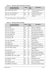
... * PEI 7B Internal Graphic device early Initialization PEI_HECI_INIT* PEI 7C HECI Initialization PEI_WATCHDOG_INIT* PEI 7D Watchdog timer Initialization PEI_MEMORY_INIT PEI 7E Memory Initial for Crisis Recovery PEI_MEMORY_INSTALL PEI 80 Simple Memory test PEI_TXTPEI* PEI 81 TXT function early Initialization PEI_SWITCH_STACK PEI 82 Start to maximum level SEC_GO_TO_SECSTARTUP SEC 09 Setup BIOS...
... * PEI 7B Internal Graphic device early Initialization PEI_HECI_INIT* PEI 7C HECI Initialization PEI_WATCHDOG_INIT* PEI 7D Watchdog timer Initialization PEI_MEMORY_INIT PEI 7E Memory Initial for Crisis Recovery PEI_MEMORY_INSTALL PEI 80 Simple Memory test PEI_TXTPEI* PEI 81 TXT function early Initialization PEI_SWITCH_STACK PEI 82 Start to maximum level SEC_GO_TO_SECSTARTUP SEC 09 Setup BIOS...
Aspire 7560, 7560G Service Guide
Page 188
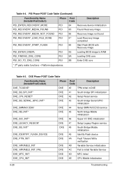
... (Continued) Functionality Name (Include\PostCode.h) Phase Post Code Description PEI_ENTER_RECOVERY_MODE PEI 84 Recovery device Initialization PEI_RECOVERY_MEDIA_FOUND PEI 85 Found Recovery image PEI_RECOVERY_MEDIA_NOT_FOUND PEI 86 Recovery image not found PEI_RECOVERY_LOAD_FILE_DONE PEI 87 Load Recovery Image completed PEI_RECOVERY_START_FLASH PEI 88 Start Flash BIOS with Recovery image PEI_ENTER_DXEIPL PEI 89 Loading BIOS image to initial Variable Service DXE_MTC_INIT...
... (Continued) Functionality Name (Include\PostCode.h) Phase Post Code Description PEI_ENTER_RECOVERY_MODE PEI 84 Recovery device Initialization PEI_RECOVERY_MEDIA_FOUND PEI 85 Found Recovery image PEI_RECOVERY_MEDIA_NOT_FOUND PEI 86 Recovery image not found PEI_RECOVERY_LOAD_FILE_DONE PEI 87 Load Recovery Image completed PEI_RECOVERY_START_FLASH PEI 88 Start Flash BIOS with Recovery image PEI_ENTER_DXEIPL PEI 89 Loading BIOS image to initial Variable Service DXE_MTC_INIT...
Aspire 7560, 7560G Service Guide
Page 191
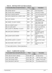
... No Boot Device POST_BDS FB UEFI Boot Start Image POST_BDS FD Legacy 16 boot entry POST_BDS FE Try to Legacy OS. BDS_RECOVERY_START_FLASH BDS 35 Fast Recovery Start Flash. * 3rd party relate functions - BDS_ENTER_LEGACY_16_BOOT BDS 34 Ready to Boot Legacy OS. Platform dependence. Table 4-7. Table 4-6.
... No Boot Device POST_BDS FB UEFI Boot Start Image POST_BDS FD Legacy 16 boot entry POST_BDS FE Try to Legacy OS. BDS_RECOVERY_START_FLASH BDS 35 Fast Recovery Start Flash. * 3rd party relate functions - BDS_ENTER_LEGACY_16_BOOT BDS 34 Ready to Boot Legacy OS. Platform dependence. Table 4-7. Table 4-6.
Aspire 7560, 7560G Service Guide
Page 196
Mainboard Top 5-3 Mainboard Bottom 5-4 Clearing Password and BIOS Recovery 5-5 Clearing Password 5-5 BIOS Recovery by Crisis Disk 5-6 5-2
Mainboard Top 5-3 Mainboard Bottom 5-4 Clearing Password and BIOS Recovery 5-5 Clearing Password 5-5 BIOS Recovery by Crisis Disk 5-6 5-2
Aspire 7560, 7560G Service Guide
Page 199
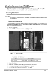
... and press F2 to enter BIOS Utility Setup menu. 5. Clearing Password and BIOS Recovery 0 This section provides users with the following procedure is shown, repeat steps 1 through 5. Remove AC adapter. 2. If no password prompt is shown, BIOS password is set, the BIOS will prompt for the Acer Aspire 7560/7560G. Plug in AC adapter. 4.
... and press F2 to enter BIOS Utility Setup menu. 5. Clearing Password and BIOS Recovery 0 This section provides users with the following procedure is shown, repeat steps 1 through 5. Remove AC adapter. 2. If no password prompt is shown, BIOS password is set, the BIOS will prompt for the Acer Aspire 7560/7560G. Plug in AC adapter. 4.
Aspire 7560, 7560G Service Guide
Page 200
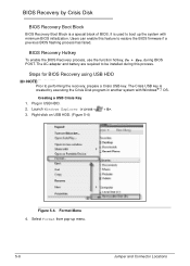
... Crisis Key 0 1. Format Menu 4. Users can enable this process. Right-click on USB HDD. (Figure 5-4) Figure 5-4. BIOS Recovery Hotkey 0 To enable the BIOS Recovery process, use the function hotkey, Fn + Esc, during this feature to be installed during BIOS POST. Plug in another system with... minimum BIOS initialization. BIOS Recovery by Crisis Disk 0 BIOS Recovery Boot Block 0 BIOS Recovery Boot Block is created by executing the Crisis Disk program in USB HDD. 2. Steps for BIOS Recovery using USB HDD 0 NOTE: NOTE: Prior to boot up ...
... Crisis Key 0 1. Format Menu 4. Users can enable this process. Right-click on USB HDD. (Figure 5-4) Figure 5-4. BIOS Recovery Hotkey 0 To enable the BIOS Recovery process, use the function hotkey, Fn + Esc, during this feature to be installed during BIOS POST. Plug in another system with... minimum BIOS initialization. BIOS Recovery by Crisis Disk 0 BIOS Recovery Boot Block 0 BIOS Recovery Boot Block is created by executing the Crisis Disk program in USB HDD. 2. Steps for BIOS Recovery using USB HDD 0 NOTE: NOTE: Prior to boot up ...


