
Aspire 6530/6530G Quick Guide
Page 8
... 89 Replacing the LCD Panel 89 Replacing the LCD Bezel 93 Main Module Reassembly Procedure 95 Replacing the CPU 95 Replacing the Thermal Module 95 Replacing the Mainboard 97 Replacing the Bluetooth Board 99 Replacing the Modem Module 99 Replacing the Finger Print Reader 100 Replacing the Upper Cover 102 Replacing the LCD Module 104 Replacing the Speaker Module 107 Replacing the Keyboard 107 Replacing the...
... 89 Replacing the LCD Panel 89 Replacing the LCD Bezel 93 Main Module Reassembly Procedure 95 Replacing the CPU 95 Replacing the Thermal Module 95 Replacing the Mainboard 97 Replacing the Bluetooth Board 99 Replacing the Modem Module 99 Replacing the Finger Print Reader 100 Replacing the Upper Cover 102 Replacing the LCD Module 104 Replacing the Speaker Module 107 Replacing the Keyboard 107 Replacing the...
Aspire 6530/6530G Quick Guide
Page 9
... Recovery 147 Clearing Password Check 147 BIOS Recovery by Crisis Disk 148 FRU (Field Replaceable Unit) List 149 Aspire 6530 Exploded Diagrams 150 Main Module 150 LCD Module 151 Aspire 6530 FRU List 152 Screw List 161 Model Definition and Configuration 164 Aspire 6530 Series 164 Test Compatible Components 201 Microsoft® Windows® Vista Environment Test 202...
... Recovery 147 Clearing Password Check 147 BIOS Recovery by Crisis Disk 148 FRU (Field Replaceable Unit) List 149 Aspire 6530 Exploded Diagrams 150 Main Module 150 LCD Module 151 Aspire 6530 FRU List 152 Screw List 161 Model Definition and Configuration 164 Aspire 6530 Series 164 Test Compatible Components 201 Microsoft® Windows® Vista Environment Test 202...

Aspire 6530/6530G Quick Guide
Page 99
Align the LCD brackets with the eight screw holes (four on each side) on the LCD Panel as shown. Chapter 3 89 Secure the LCD brackets to the LCD panel. 3. Secure the cable by replacing the securing strip. Insert the LCD Panel cable into the LCD Panel as shown. 2. Turn the panel over. LCD Module Reassembly Procedure Replacing the LCD Panel 1.
Align the LCD brackets with the eight screw holes (four on each side) on the LCD Panel as shown. Chapter 3 89 Secure the LCD brackets to the LCD panel. 3. Secure the cable by replacing the securing strip. Insert the LCD Panel cable into the LCD Panel as shown. 2. Turn the panel over. LCD Module Reassembly Procedure Replacing the LCD Panel 1.

Aspire 6530/6530G Quick Guide
Page 100
4. Turn the LCD Panel over and re-insert the LCD cable into the bracket wells as shown. 90 Chapter 3 Align the brackets with the edge of the panel. 5. Replace the remaining securing strips and press down along the length of the cable to secure it in place ensuring the cable ends are in line with the alignment wells in the back panel and lower the LCD brackets into the hinge retainer. 6.
4. Turn the LCD Panel over and re-insert the LCD cable into the bracket wells as shown. 90 Chapter 3 Align the brackets with the edge of the panel. 5. Replace the remaining securing strips and press down along the length of the cable to secure it in place ensuring the cable ends are in line with the alignment wells in the back panel and lower the LCD brackets into the hinge retainer. 6.

Aspire 6530/6530G Quick Guide
Page 101
NOTE: Ensure the CMOS and Inverter cables are not under the LCD Panel and correctly aligned. 8. Connect the Camera Module cable as shown. Pivot the LCD Panel down in place. Locate the alignment pins (2) and replace the Camera Board taking care the pins protrude through the sockets. 10. Replace the six screws to secure the panel within the LCD module. 9. 7. Chapter 3 91
NOTE: Ensure the CMOS and Inverter cables are not under the LCD Panel and correctly aligned. 8. Connect the Camera Module cable as shown. Pivot the LCD Panel down in place. Locate the alignment pins (2) and replace the Camera Board taking care the pins protrude through the sockets. 10. Replace the six screws to secure the panel within the LCD module. 9. 7. Chapter 3 91

Aspire 6530/6530G Quick Guide
Page 103
Chapter 3 93 Continue to lock the upper and lower covers in place. 3. Align the hinge covers taking care to tuck in all cabling, and lower the bezel down in place to press the bezel down in place. Align the edge of the bezel with the bottom cover and reconnect the Mic Cable. 2. Replacing the LCD Bezel 1.
Chapter 3 93 Continue to lock the upper and lower covers in place. 3. Align the hinge covers taking care to tuck in all cabling, and lower the bezel down in place to press the bezel down in place. Align the edge of the bezel with the bottom cover and reconnect the Mic Cable. 2. Replacing the LCD Bezel 1.

Aspire 6530/6530G Quick Guide
Page 104
4. Replace the ten securing screws and screw caps on the LCD bezel. 94 Chapter 3
4. Replace the ten securing screws and screw caps on the LCD bezel. 94 Chapter 3

Aspire 6530/6530G Quick Guide
Page 114
Replace the four securing screws (two on the bottom panel. Carefully align the LCD module over . Turn the computer over the hinge sockets and lower the module into the chassis, taking care not to trap the LCD cables. 2. Replacing the LCD Module 1. Replace the ten screws on each side) securing the LCD module. 104 Chapter 3 4.
Replace the four securing screws (two on the bottom panel. Carefully align the LCD module over . Turn the computer over the hinge sockets and lower the module into the chassis, taking care not to trap the LCD cables. 2. Replacing the LCD Module 1. Replace the ten screws on each side) securing the LCD module. 104 Chapter 3 4.

Aspire 6530/6530G Quick Guide
Page 115
Reconnect the cables as shown, taking care to follow the cable guides and clips. The upper channel holds the AC power cable and the lower channel holds the LCD power cable. 4. AC Power Cable LCD Power Cable 5. Replace the antenna and backlight cables as shown. Backlight Cable Antenna Cable Chapter 3 105 3. Replace the LCD power cable and AC power cable in the cable guides and clips as shown. NOTE: There are two cable channels.
Reconnect the cables as shown, taking care to follow the cable guides and clips. The upper channel holds the AC power cable and the lower channel holds the LCD power cable. 4. AC Power Cable LCD Power Cable 5. Replace the antenna and backlight cables as shown. Backlight Cable Antenna Cable Chapter 3 105 3. Replace the LCD power cable and AC power cable in the cable guides and clips as shown. NOTE: There are two cable channels.

Aspire 6530/6530G Quick Guide
Page 124
Insert the TV Tuner into the socket as shown. 2. Replacing the VGA Module 1. Insert the TV Tuner in to the socket. 3. Attach the cable as shown. 2. Replace the four securing screws. 114 Chapter 3 Replacing the TV Tuner Module 1. Replace the two securing screws. 4. Insert the VGA module into the bracket as shown, ensuring that the TV Tuner antenna follows the installation pattern of the LCD antenna cables.
Insert the TV Tuner into the socket as shown. 2. Replacing the VGA Module 1. Insert the TV Tuner in to the socket. 3. Attach the cable as shown. 2. Replace the four securing screws. 114 Chapter 3 Replacing the TV Tuner Module 1. Replace the two securing screws. 4. Insert the VGA module into the bracket as shown, ensuring that the TV Tuner antenna follows the installation pattern of the LCD antenna cables.
Aspire 6530/6530G Quick Guide
Page 129
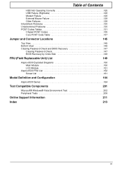
... port replicators or docking stations. If the computer boots correctly, add the devices one by one until the failure point is no power, see "LCD Failure" on page 42). 8. Chapter 4 119 Connect an external monitor to the computer and switch between the internal display and the external display ...the Display doesn't work, perform the following occurs: • Fans start up • Status LEDs light up If there is discovered. 6. Do not replace a non-defective FRUs: No POST or Video If the POST or video doesn't display, perform the following actions one of the following actions one at...
... port replicators or docking stations. If the computer boots correctly, add the devices one by one until the failure point is no power, see "LCD Failure" on page 42). 8. Chapter 4 119 Connect an external monitor to the computer and switch between the internal display and the external display ...the Display doesn't work, perform the following occurs: • Fans start up • Status LEDs light up If there is discovered. 6. Do not replace a non-defective FRUs: No POST or Video If the POST or video doesn't display, perform the following actions one of the following actions one at...

Aspire 6530/6530G Quick Guide
Page 130
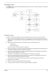
..., check the view settings and control/mouse wheel zoom feature in the same location, the LCD is experiencing intermittent loss of BIOS Settings If the computer is faulty and should be replaced. Readjust if necessary. 6. Random Loss of BIOS information, perform the following actions one at... and follow the onscreen prompts. 11. If extensive pixel damage is faulty and should be replaced. b. If desktop display resolution is not normal, right-click on the screen), the LCD is present (different colored spots in the same locations on the desktop and select Personalize´...
..., check the view settings and control/mouse wheel zoom feature in the same location, the LCD is experiencing intermittent loss of BIOS Settings If the computer is faulty and should be replaced. Readjust if necessary. 6. Random Loss of BIOS information, perform the following actions one at... and follow the onscreen prompts. 11. If extensive pixel damage is faulty and should be replaced. b. If desktop display resolution is not normal, right-click on the screen), the LCD is present (different colored spots in the same locations on the desktop and select Personalize´...

Aspire 6530/6530G Quick Guide
Page 131
Do not replace a non-defective FRUs: Chapter 4 121 Do not replace a nondefective FRUs: Built-In Keyboard Failure If the built-in Keyboard fails, perform the following actions one at a time to correct the problem. LCD Failure If the LCD fails, perform the following actions one at a time to correct the problem.
Do not replace a non-defective FRUs: Chapter 4 121 Do not replace a nondefective FRUs: Built-In Keyboard Failure If the built-in Keyboard fails, perform the following actions one at a time to correct the problem. LCD Failure If the LCD fails, perform the following actions one at a time to correct the problem.
Aspire 6530/6530G Quick Guide
Page 140
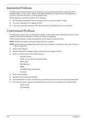
... a time until you find the failing FRU. 7. Run the advanced diagnostic test for damage. Rerun the test to do the following devices: • Non-Acer devices • Printer, mouse, and other external devices • Battery pack • Hard disk drive • DIMM • CD-ROM/Diskette drive Module... that there are no error is detected, do not isolate non-defective FRU). Determine if the problem has changed. 6. Do not replace a non-defective FRU: • System board • LCD assembly 130 Chapter 4 FRU replacement should be caused by the computer. If no more errors.
... a time until you find the failing FRU. 7. Run the advanced diagnostic test for damage. Rerun the test to do the following devices: • Non-Acer devices • Printer, mouse, and other external devices • Battery pack • Hard disk drive • DIMM • CD-ROM/Diskette drive Module... that there are no error is detected, do not isolate non-defective FRU). Determine if the problem has changed. 6. Do not replace a non-defective FRU: • System board • LCD assembly 130 Chapter 4 FRU replacement should be caused by the computer. If no more errors.


