Aspire 5920/5920G User's Guide EN
Page 4
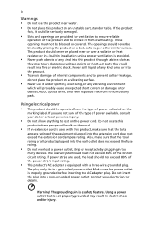
...-out parts that could be blocked or covered. Do not locate this product where people will probably cause unexpected short current or damage rotor devices, HDD, Optical drive, and even exposure risk from lithium battery pack. If power strips are not sure of the type of the equipment plugged into a non...
...-out parts that could be blocked or covered. Do not locate this product where people will probably cause unexpected short current or damage rotor devices, HDD, Optical drive, and even exposure risk from lithium battery pack. If power strips are not sure of the type of the equipment plugged into a non...
Aspire 5920/5920G User's Guide EN
Page 43
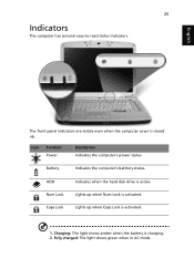
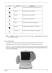
25 Indicators The computer has serveral easy-to-read status indicators. Icon Function Power Description Indicates the computer's power status. Lights up when Num Lock is activated. HDD Num Lock Caps Lock Indicates when the hard disk drive is charging. 2. Lights up when Caps Lock is closed up. Charging: The light shows amber when the battery is active. Fully charged: The light shows green when in AC mode. Battery Indicates the computer's batttery status. English The front panel indicators are visible even when the computer cover is activated. 1.
25 Indicators The computer has serveral easy-to-read status indicators. Icon Function Power Description Indicates the computer's power status. Lights up when Num Lock is activated. HDD Num Lock Caps Lock Indicates when the hard disk drive is charging. 2. Lights up when Caps Lock is closed up. Charging: The light shows amber when the battery is active. Fully charged: The light shows green when in AC mode. Battery Indicates the computer's batttery status. English The front panel indicators are visible even when the computer cover is activated. 1.
Aspire 5920/5920G Service Guide
Page 8
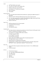
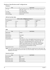
...: Bluetooth® 2.0+EDR (Enhanced Data Rate) T Integrated Kedron-n 3945abg network connection (dual-band tri-mode 802.11a/b/g/n) Wi-Fi CERTIFIEDTM solution, supporting Acer SignalUpTM wireless technology Mini Cards T T Two mini card slots (one supports a wireless module, the other a TV, 3G, or MPEG decoder module) 3G...in microphone T VoIP-enabled Storage subsystem T One or two 60/80/100/120 GB Serial ATA hard disk drive, supporting Ultra DMA100 S.M.A.R.T / Hybrid HDD T Optical drive options: DVD-Super Multi double-layer drive, Blue-ray drive (slot-load) T 5-in -1 card reader (SD/MMC/MS/MS ...
...: Bluetooth® 2.0+EDR (Enhanced Data Rate) T Integrated Kedron-n 3945abg network connection (dual-band tri-mode 802.11a/b/g/n) Wi-Fi CERTIFIEDTM solution, supporting Acer SignalUpTM wireless technology Mini Cards T T Two mini card slots (one supports a wireless module, the other a TV, 3G, or MPEG decoder module) 3G...in microphone T VoIP-enabled Storage subsystem T One or two 60/80/100/120 GB Serial ATA hard disk drive, supporting Ultra DMA100 S.M.A.R.T / Hybrid HDD T Optical drive options: DVD-Super Multi double-layer drive, Blue-ray drive (slot-load) T 5-in -1 card reader (SD/MMC/MS/MS ...
Aspire 5920/5920G Service Guide
Page 12
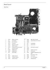
... CN35 25 VR1 26 CN30 27 CN37 28 CN36 29 CN38 30 U37 IEEE 1394 Connector Optical Disk Drive Connector South Bridge Audio Codec SATA HDD Connector Speaker Connector Volume Dial Headphones/Speaker/Line-out Jack Microphone-in Jack Line-in Jack 5-in-1 Card Reader Infrared Sensor 6 Chapter 1
... CN35 25 VR1 26 CN30 27 CN37 28 CN36 29 CN38 30 U37 IEEE 1394 Connector Optical Disk Drive Connector South Bridge Audio Codec SATA HDD Connector Speaker Connector Volume Dial Headphones/Speaker/Line-out Jack Microphone-in Jack Line-in Jack 5-in-1 Card Reader Infrared Sensor 6 Chapter 1
Aspire 5920/5920G Service Guide
Page 13
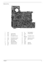
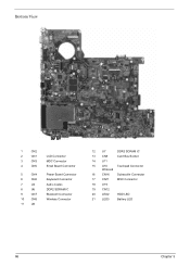
Bottom View 1 2 3 7 11 4 8 12 5 6 9 10 13 15 16 14 17 18 19 20 21 1 CN2 2 CN1 3 CN3 4 CN5 5 CN4 6 CN6 7 U4 8 U6 9 CN7 10 CN8 11 U8 LCD Connector MDC Connector Email Board Connector Power Board Connector Keyboard Connector Audio Codec DDR2 SDRAM IC Bluetooth Connector Wireless Connector 12 U7 DDR2 SDRAM IC 13 CN9 Card Bus Socket 14 U11 15 U10 Touchpad Connector Winbond 16 CN16 Subwoofer Connector 17 CN11 MSC Connector 18 U19 19 CN12 20 LED2 HDD LED 21 LED3 Battery LED Chapter 1 7
Bottom View 1 2 3 7 11 4 8 12 5 6 9 10 13 15 16 14 17 18 19 20 21 1 CN2 2 CN1 3 CN3 4 CN5 5 CN4 6 CN6 7 U4 8 U6 9 CN7 10 CN8 11 U8 LCD Connector MDC Connector Email Board Connector Power Board Connector Keyboard Connector Audio Codec DDR2 SDRAM IC Bluetooth Connector Wireless Connector 12 U7 DDR2 SDRAM IC 13 CN9 Card Bus Socket 14 U11 15 U10 Touchpad Connector Winbond 16 CN16 Subwoofer Connector 17 CN11 MSC Connector 18 U19 19 CN12 20 LED2 HDD LED 21 LED3 Battery LED Chapter 1 7
Aspire 5920/5920G Service Guide
Page 19
...and one userprogrammable button. Charging: The light shows amber when the battery is active. To set to run the Acer Launch Manager. Icon Function Description Icon Function HDD Description Indicates when the hard disc or optical drive is charging. 2. Num lock Lights when Num Lock is being ...charged. Wireless LAN Indicates the status of the keyboard there are pre-set the Web browser, mail and programmable buttons, run the Acer Empowering Technology...
...and one userprogrammable button. Charging: The light shows amber when the battery is active. To set to run the Acer Launch Manager. Icon Function Description Icon Function HDD Description Indicates when the hard disc or optical drive is charging. 2. Num lock Lights when Num Lock is being ...charged. Wireless LAN Indicates the status of the keyboard there are pre-set the Web browser, mail and programmable buttons, run the Acer Empowering Technology...

Aspire 5920/5920G Service Guide
Page 31
... disks provided by the manufacturer. T Recover from a hidden partition (factory defaults). The Acer eRecovery Management utility occupies space in a hidden partition on D:\ drive. T Image/data backup: T Back up to HDD (set recovery point). T Back up to CD/DVD. Acer eRecovery Management Acer eRecovery Management is a powerful utility that does away with : T Password protection. To...
... disks provided by the manufacturer. T Recover from a hidden partition (factory defaults). The Acer eRecovery Management utility occupies space in a hidden partition on D:\ drive. T Image/data backup: T Back up to HDD (set recovery point). T Back up to CD/DVD. Acer eRecovery Management Acer eRecovery Management is a powerful utility that does away with : T Password protection. To...
Aspire 5920/5920G Service Guide
Page 36
... ROM type BIOS ROM size BIOS package Supported protocols BIOS password control Phoenix Specification Flash ROM 1MB 8 pin SOIC ACPI 1.0b/2.0/3.0, PCI 2.2, System/HDD Password Security Control, INT 13h Extensions, PnP BIOS 1.0a, SMBIOS 2.4, Simple Boot Flag 1.0, Boot Block, PCI Bus Power Management Interface Specification, USB1...setup manual NOTE: If you will see PXE version displaying on the screen. After that, power off the system and remove the HDD. Last, reboot the laptop. Second Level Cache Item Cache controller Cache size 1st level cache control 2st level cache control Cache scheme...
... ROM type BIOS ROM size BIOS package Supported protocols BIOS password control Phoenix Specification Flash ROM 1MB 8 pin SOIC ACPI 1.0b/2.0/3.0, PCI 2.2, System/HDD Password Security Control, INT 13h Extensions, PnP BIOS 1.0a, SMBIOS 2.4, Simple Boot Flag 1.0, Boot Block, PCI Bus Power Management Interface Specification, USB1...setup manual NOTE: If you will see PXE version displaying on the screen. After that, power off the system and remove the HDD. Last, reboot the laptop. Second Level Cache Item Cache controller Cache size 1st level cache control 2st level cache control Cache scheme...

Aspire 5920/5920G Service Guide
Page 45
...the serial number of this unit. This field displays the manufacturer of this system. This field displays the VGA firmware version of HDD installed on primary IDE master. Information Information Main Phoenix TrustedCore(tm) Setup Utility Security Boot Exit CPU Type : CPU Speed :...v0.2412 VGA BIOS Version: nVidia 0.84.41.00.08 Serial Number: xxxxxxxxxxxxxxxxxxxxxx Asset Tag Number: Produce Name: Manufacturer Name: Acer UUID: xxxxxxxxxxxxxxxxxxxxxxxxxxxxxxxx F1 Help Esc Exit Select Item Select Menu F5/F6 Change Values Enter Select Sub-Menu NOTE: The system ...
...the serial number of this unit. This field displays the manufacturer of this system. This field displays the VGA firmware version of HDD installed on primary IDE master. Information Information Main Phoenix TrustedCore(tm) Setup Utility Security Boot Exit CPU Type : CPU Speed :...v0.2412 VGA BIOS Version: nVidia 0.84.41.00.08 Serial Number: xxxxxxxxxxxxxxxxxxxxxx Asset Tag Number: Produce Name: Manufacturer Name: Acer UUID: xxxxxxxxxxxxxxxxxxxxxxxxxxxxxxxx F1 Help Esc Exit Select Item Select Menu F5/F6 Change Values Enter Select Sub-Menu NOTE: The system ...
Aspire 5920/5920G Service Guide
Page 52
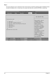
...) Setup Utility Security Boot Exit Item Specific Help Boot priority order: 1: PCI BEV : MBA v9.4.5 Slot 0800 2: USB FDC : 3: IDE HDD: ST980811AS-(S1) 4: IDE CD : Optiarc DVD RW AD-7530A-(P 5: USB HDD : 6: USB CDROM : 7: USB KEY : 8: Excluded from boot order : Keys used to view or configure devices : Up and Down arrows select...
...) Setup Utility Security Boot Exit Item Specific Help Boot priority order: 1: PCI BEV : MBA v9.4.5 Slot 0800 2: USB FDC : 3: IDE HDD: ST980811AS-(S1) 4: IDE CD : Optiarc DVD RW AD-7530A-(P 5: USB HDD : 6: USB CDROM : 7: USB KEY : 8: Excluded from boot order : Keys used to view or configure devices : Up and Down arrows select...
Aspire 5920/5920G Service Guide
Page 57
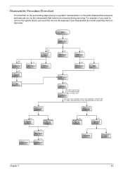
... need to be removed during servicing. Start Battery Pack B*1 D*1 System Fan B*4 Thermal Module F*1 ODD Module CPU D*5 F*1 Thermal Door Memory Lower Case Assembly F*1 Mimi Cover F*2 HDD Door H*4 HDD Bracket HDD Middle Cover F*2 Keyboard C*2 LCD hinges to logic D*2 LCD hinges to logic C*2 on bottom side LCD Module C*8 upper case assembly to lower case assembly on...
... need to be removed during servicing. Start Battery Pack B*1 D*1 System Fan B*4 Thermal Module F*1 ODD Module CPU D*5 F*1 Thermal Door Memory Lower Case Assembly F*1 Mimi Cover F*2 HDD Door H*4 HDD Bracket HDD Middle Cover F*2 Keyboard C*2 LCD hinges to logic D*2 LCD hinges to logic C*2 on bottom side LCD Module C*8 upper case assembly to lower case assembly on...

Aspire 5920/5920G Service Guide
Page 60
... as shown. 5. Removing the ODD Module 6. Removing the Memory and Wireless LAN Card 8. Lift the back panel up . 56 Chapter 3 Removing the HDD Modules/ODD Module/Memory/Wireless LAN Card/VGA Board/Thermal Module and the LCD Module To access the intenal laptop components, you have to gently ... the snaps securing the memory in place. The memory will pop up as shown. Use a flat screwdriver to first remove the back panel. 1. Removing the HDD Module 3. Pull up the HDD module by the two brackets as shown. Remove the screw fastening the ODD module. 7.
... as shown. 5. Removing the ODD Module 6. Removing the Memory and Wireless LAN Card 8. Lift the back panel up . 56 Chapter 3 Removing the HDD Modules/ODD Module/Memory/Wireless LAN Card/VGA Board/Thermal Module and the LCD Module To access the intenal laptop components, you have to gently ... the snaps securing the memory in place. The memory will pop up as shown. Use a flat screwdriver to first remove the back panel. 1. Removing the HDD Module 3. Pull up the HDD module by the two brackets as shown. Remove the screw fastening the ODD module. 7.
Aspire 5920/5920G Service Guide
Page 71
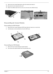
Remove the two screws fastening the right LCD bracket and detach it. 10. Disconnect the LCD cable from the LCD cover and remove the CMOS module. Detach the CMOS cable from the LCD. 11. Remove the two screws holding the HDD (hard disk drive) case; Chapter 3 67 Disassembling the ODD Module 1. Disassembling the External Modules Disassembling the HDD Module 1. Then remove the optical bracket from the HDD case. Carefully take out the hard disk drive from the optical disk drive. two on each side. 2. Remove the four screws holding the optical bracket. 2. 9.
Remove the two screws fastening the right LCD bracket and detach it. 10. Disconnect the LCD cable from the LCD cover and remove the CMOS module. Detach the CMOS cable from the LCD. 11. Remove the two screws holding the HDD (hard disk drive) case; Chapter 3 67 Disassembling the ODD Module 1. Disassembling the External Modules Disassembling the HDD Module 1. Then remove the optical bracket from the HDD case. Carefully take out the hard disk drive from the optical disk drive. two on each side. 2. Remove the four screws holding the optical bracket. 2. 9.
Aspire 5920/5920G Service Guide
Page 91
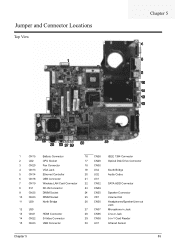
... CN35 25 VR1 26 CN30 27 CN37 28 CN36 29 CN38 30 U37 IEEE 1394 Connector Optical Disk Drive Connector South Bridge Audio Codec SATA HDD Connector Speaker Connector Volume Dial Headphones/Speaker/Line-out Jack Microphone-in Jack Line-in Jack 5-in-1 Card Reader Infrared Sensor Chapter 5 85
... CN35 25 VR1 26 CN30 27 CN37 28 CN36 29 CN38 30 U37 IEEE 1394 Connector Optical Disk Drive Connector South Bridge Audio Codec SATA HDD Connector Speaker Connector Volume Dial Headphones/Speaker/Line-out Jack Microphone-in Jack Line-in Jack 5-in-1 Card Reader Infrared Sensor Chapter 5 85
Aspire 5920/5920G Service Guide
Page 92
Bottom View 1 2 3 7 11 4 8 12 5 6 9 10 13 15 16 14 17 18 19 20 21 1 CN2 2 CN1 3 CN3 4 CN5 5 CN4 6 CN6 7 U4 8 U6 9 CN7 10 CN8 11 U8 LCD Connector MDC Connector Email Board Connector Power Board Connector Keyboard Connector Audio Codec DDR2 SDRAM IC Bluetooth Connector Wireless Connector 12 U7 DDR2 SDRAM IC 13 CN9 Card Bus Socket 14 U11 15 U10 Touchpad Connector Winbond 16 CN16 Subwoofer Connector 17 CN11 MSC Connector 18 U19 19 CN12 20 LED2 HDD LED 21 LED3 Battery LED 86 Chapter 5
Bottom View 1 2 3 7 11 4 8 12 5 6 9 10 13 15 16 14 17 18 19 20 21 1 CN2 2 CN1 3 CN3 4 CN5 5 CN4 6 CN6 7 U4 8 U6 9 CN7 10 CN8 11 U8 LCD Connector MDC Connector Email Board Connector Power Board Connector Keyboard Connector Audio Codec DDR2 SDRAM IC Bluetooth Connector Wireless Connector 12 U7 DDR2 SDRAM IC 13 CN9 Card Bus Socket 14 U11 15 U10 Touchpad Connector Winbond 16 CN16 Subwoofer Connector 17 CN11 MSC Connector 18 U19 19 CN12 20 LED2 HDD LED 21 LED3 Battery LED 86 Chapter 5


