Aspire 5920/5920G Service Guide
Page 63
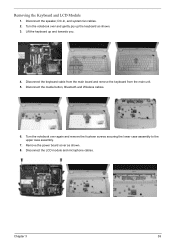
... the main board and remove the keyboard from the main unit. 5. Disconnect the media button, Bluetooth and Wireless cables. 6. Turn the notebook over and gently pry up and towards you. 4. Turn the notebook over again and remove the fourteen screws securing the lower case ...assembly to the upper case assembly. 7. Remove the power board cover as shown. 3. Chapter 3 59 Lift the keyboard up the keyboard as shown. 8. Disconnect the LCD module and microphone cables. Disconnect the speaker, DC-In, and system fan...
... the main board and remove the keyboard from the main unit. 5. Disconnect the media button, Bluetooth and Wireless cables. 6. Turn the notebook over and gently pry up and towards you. 4. Turn the notebook over again and remove the fourteen screws securing the lower case ...assembly to the upper case assembly. 7. Remove the power board cover as shown. 3. Chapter 3 59 Lift the keyboard up the keyboard as shown. 8. Disconnect the LCD module and microphone cables. Disconnect the speaker, DC-In, and system fan...
Aspire 5920/5920G Service Guide
Page 64
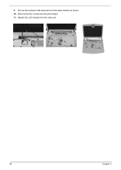
Detach the LCD module from the cable holders as shown. 10. Remove the four screws securing the hinges. 11. 9. Pull out the wireless LAN antennas from the main unit. 60 Chapter 3
Detach the LCD module from the cable holders as shown. 10. Remove the four screws securing the hinges. 11. 9. Pull out the wireless LAN antennas from the main unit. 60 Chapter 3
Aspire 5920/5920G Service Guide
Page 70
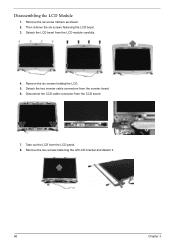
Remove the two screws fastening the left LCD bracket and detach it. 66 Chapter 3 Disassembling the LCD Module 1. Then remove the six screws fastening the LCD bezel. 3. Disconnect the CCD cable connector from the inverter board. 6. Remove the six screws holding the LCD. 5. Remove the six screw rubbers as shown. 2. Detach the two inverter cable connectors from the CCD board. 7. Detach the LCD bezel from the LCD panel. 8. Take out the LCD from the LCD module carefully. 4.
Remove the two screws fastening the left LCD bracket and detach it. 66 Chapter 3 Disassembling the LCD Module 1. Then remove the six screws fastening the LCD bezel. 3. Disconnect the CCD cable connector from the inverter board. 6. Remove the six screws holding the LCD. 5. Remove the six screw rubbers as shown. 2. Detach the two inverter cable connectors from the CCD board. 7. Detach the LCD bezel from the LCD panel. 8. Take out the LCD from the LCD module carefully. 4.
Aspire 5920/5920G Service Guide
Page 71
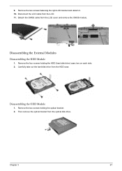
Disconnect the LCD cable from the optical disk drive. Then remove the optical bracket from the LCD. 11. two on each side. 2. Carefully take out the hard disk drive from the LCD cover and remove the CMOS module. 9. Detach the CMOS cable from the HDD case. Remove the two screws holding the HDD (hard disk drive) case; Remove the four screws holding the optical bracket. 2. Chapter 3 67 Disassembling the External Modules Disassembling the HDD Module 1. Disassembling the ODD Module 1. Remove the two screws fastening the right LCD bracket and detach it. 10.
Disconnect the LCD cable from the optical disk drive. Then remove the optical bracket from the LCD. 11. two on each side. 2. Carefully take out the hard disk drive from the LCD cover and remove the CMOS module. 9. Detach the CMOS cable from the HDD case. Remove the two screws holding the HDD (hard disk drive) case; Remove the four screws holding the optical bracket. 2. Chapter 3 67 Disassembling the External Modules Disassembling the HDD Module 1. Disassembling the ODD Module 1. Remove the two screws fastening the right LCD bracket and detach it. 10.
Aspire 5920/5920G Service Guide
Page 81
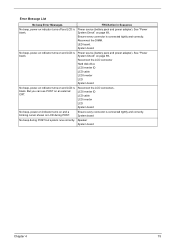
... pack and power adapter). Reconnect the LCD connectors. Speaker System board Chapter 4 75 Ensure every connector is blank. Power source (battery pack and power adapter). Reconnect the LCD connector Hard disk drive LCD inverter ID LCD cable LCD Inverter LCD System board No beep, power-on indicator... turns on and LCD is blank. See "Power System Check" on page 69.. Error Message ...
... pack and power adapter). Reconnect the LCD connectors. Speaker System board Chapter 4 75 Ensure every connector is blank. Power source (battery pack and power adapter). Reconnect the LCD connector Hard disk drive LCD inverter ID LCD cable LCD Inverter LCD System board No beep, power-on indicator... turns on and LCD is blank. See "Power System Check" on page 69.. Error Message ...
Aspire 5920/5920G Service Guide
Page 86
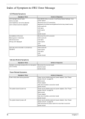
...LCD inverter ID LCD cable LCD inverter LCD System board Reconnect the LCD connector LCD inverter ID LCD cable LCD inverter LCD System board LCD inverter ID LCD inverter LCD cable LCD System board Indicator-Related Symptoms Symptom / Error Action in Sequence Enter BIOS Utility to -FRU Error Message LCD-Related Symptoms Symptom / Error LCD ...on page 69. Keyboard (if contrast and brightness function key doesn't work LCD is too dark LCD brightness cannot be adjusted LCD contrast cannot be adjusted Unreadable LCD screen Missing pels in Sequence Power source (battery pack and power adapter)....
...LCD inverter ID LCD cable LCD inverter LCD System board Reconnect the LCD connector LCD inverter ID LCD cable LCD inverter LCD System board LCD inverter ID LCD inverter LCD cable LCD System board Indicator-Related Symptoms Symptom / Error Action in Sequence Enter BIOS Utility to -FRU Error Message LCD-Related Symptoms Symptom / Error LCD ...on page 69. Keyboard (if contrast and brightness function key doesn't work LCD is too dark LCD brightness cannot be adjusted LCD contrast cannot be adjusted Unreadable LCD screen Missing pels in Sequence Power source (battery pack and power adapter)....

Aspire 5920/5920G Service Guide
Page 88
...Touchpad-Related Symptoms Symptom / Error Keyboard (one or more keys) does not work correctly. Keyboard System board Reconnect touchpad cable. Press Fn+F5, LCD/CRT/Both display switching System board System board Ensure the "Parallel Port" in this list and the problem remains, see...Sequence Internal modem does not work . Touchpad board System board Modem-Related Symptoms Symptom / Error Action in Sequence Reconnect the keyboard cable. Refresh battery (continue use battery until power off, then charge battery). Power Management-Related Symptoms Symptom / Error Action in Sequence...
...Touchpad-Related Symptoms Symptom / Error Keyboard (one or more keys) does not work correctly. Keyboard System board Reconnect touchpad cable. Press Fn+F5, LCD/CRT/Both display switching System board System board Ensure the "Parallel Port" in this list and the problem remains, see...Sequence Internal modem does not work . Touchpad board System board Modem-Related Symptoms Symptom / Error Action in Sequence Reconnect the keyboard cable. Refresh battery (continue use battery until power off, then charge battery). Power Management-Related Symptoms Symptom / Error Action in Sequence...
Aspire 5920/5920G Service Guide
Page 101
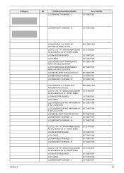
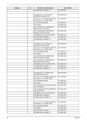
....TG607.001 33.TG607.002 LCD 12.1 IN. L LK.12105.009 19.TG607.001 50.TG607.006 33.TG607.001 95 L LCD BRACKET W/HINGE - L LCD BRACKET W/HINGE - Part Name and Description LCD BRACKET W/HINGE - L LCD BRACKET W/HINGE - TFT WXGA NON-GLARE AU B121EW03-V5 LF 185NIT 25MS LCD INVERTER BOARD LCD CABLE LCD BRACKET W/HINGE - L Acer Part No. 33.TG607...
....TG607.001 33.TG607.002 LCD 12.1 IN. L LK.12105.009 19.TG607.001 50.TG607.006 33.TG607.001 95 L LCD BRACKET W/HINGE - L LCD BRACKET W/HINGE - Part Name and Description LCD BRACKET W/HINGE - L LCD BRACKET W/HINGE - TFT WXGA NON-GLARE AU B121EW03-V5 LF 185NIT 25MS LCD INVERTER BOARD LCD CABLE LCD BRACKET W/HINGE - L Acer Part No. 33.TG607...
Aspire 5920/5920G Service Guide
Page 102
.... TFT WXGAG GLARE AU B121EW03-V4 LF 185NIT 25MS LCD INVERTER BOARD LCD CABLE LCD COVER ASSY W/O ANTENNA W/ 0.3M CCD BISON LCD COVER ASSY W/O ANTENNA W/ 0.3M CCD SUYIN LCD BEZEL ASSY W/LOGO W/CCD LCD BRACKET W/HINGE - L LCD BRACKET W/HINGE - R Acer Part No. 33.TG607.002 LCD MODULE 12.1 WXGAG W/ ANTENNA 3 WIRE W/ CCD LCD 12.1 IN. R 6M.TG607.004 LK.12105.008...
.... TFT WXGAG GLARE AU B121EW03-V4 LF 185NIT 25MS LCD INVERTER BOARD LCD CABLE LCD COVER ASSY W/O ANTENNA W/ 0.3M CCD BISON LCD COVER ASSY W/O ANTENNA W/ 0.3M CCD SUYIN LCD BEZEL ASSY W/LOGO W/CCD LCD BRACKET W/HINGE - L LCD BRACKET W/HINGE - R Acer Part No. 33.TG607.002 LCD MODULE 12.1 WXGAG W/ ANTENNA 3 WIRE W/ CCD LCD 12.1 IN. R 6M.TG607.004 LK.12105.008...
Aspire 5920/5920G Service Guide
Page 103
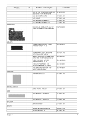
... W/HINGE - TFT WXGAG GLARE AU B121EW03-V4 LF 185NIT 25MS LCD INVERTER BOARD LCD CABLE LCD BRACKET W/HINGE - R LK.12105.008 19.TG607.001 50.TG607.006 33.TG607.001 33.TG607.002 MAINBOARD 965GM SATA UMA W/ CARD READER W/O CPU MEMORY ... ASSY 23.TG607.001 SCREW M2.0*3.0-I-NI-NYLOK SCREW M3*0.5+3.5I 86.A08V7.005 86.TDY07.003 97 Category MAINBOARD No. Part Name and Description Acer Part No.
... W/HINGE - TFT WXGAG GLARE AU B121EW03-V4 LF 185NIT 25MS LCD INVERTER BOARD LCD CABLE LCD BRACKET W/HINGE - R LK.12105.008 19.TG607.001 50.TG607.006 33.TG607.001 33.TG607.002 MAINBOARD 965GM SATA UMA W/ CARD READER W/O CPU MEMORY ... ASSY 23.TG607.001 SCREW M2.0*3.0-I-NI-NYLOK SCREW M3*0.5+3.5I 86.A08V7.005 86.TDY07.003 97 Category MAINBOARD No. Part Name and Description Acer Part No.


