User Manual
Page 17
...refer to take care of used batteries according to local regulations. Do not use liquid or aerosol cleaners. Cleaning and servicing When cleaning the computer, follow these steps: 1 Turn off before removing or replacing batteries. • Do not tamper with batteries. Keep them away from children.... • Dispose of your battery pack Here are some ways to "Frequently asked questions" on page 49 .
...refer to take care of used batteries according to local regulations. Do not use liquid or aerosol cleaners. Cleaning and servicing When cleaning the computer, follow these steps: 1 Turn off before removing or replacing batteries. • Do not tamper with batteries. Keep them away from children.... • Dispose of your battery pack Here are some ways to "Frequently asked questions" on page 49 .
User Manual
Page 19
... 26 Block and unblock devices 26 Media sharing settings 26 Power management 27 Acer PowerSmart key 27 Battery pack 28 Battery pack characteristics 28 Charging the battery 29 Optimizing battery life 29 Checking the battery level 30 Battery-low warning 30 Installing and removing the battery pack 31 Taking your notebook PC with you 32 Disconnecting from the desktop...
... 26 Block and unblock devices 26 Media sharing settings 26 Power management 27 Acer PowerSmart key 27 Battery pack 28 Battery pack characteristics 28 Charging the battery 29 Optimizing battery life 29 Checking the battery level 30 Battery-low warning 30 Installing and removing the battery pack 31 Taking your notebook PC with you 32 Disconnecting from the desktop...
User Manual
Page 46
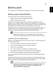
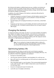
..., enabling you to recharge the battery while you travel or during a power failure. However, recharging with the computer turned off results in handy when you continue to remove the battery pack from the unit. Extreme temperatures may adversely affect the battery pack. Note: Some models have... an extra fully charged battery pack available as backup. Your computer supports charge-in-use a battery pack for details on the ...
..., enabling you to recharge the battery while you travel or during a power failure. However, recharging with the computer turned off results in handy when you continue to remove the battery pack from the unit. Extreme temperatures may adversely affect the battery pack. Note: Some models have... an extra fully charged battery pack available as backup. Your computer supports charge-in-use a battery pack for details on the ...
User Manual
Page 47
.... • Use AC power whenever possible, reserving battery for selected models). • Store the battery pack in a significantly faster charge time. Higher temperatures cause the battery to remove the battery pack after your battery to start the next day with the battery inserted. Note: You are advised to charge the battery before traveling enables you are advised to...
.... • Use AC power whenever possible, reserving battery for selected models). • Store the battery pack in a significantly faster charge time. Higher temperatures cause the battery to remove the battery pack after your battery to start the next day with the battery inserted. Note: You are advised to charge the battery before traveling enables you are advised to...
User Manual
Page 49
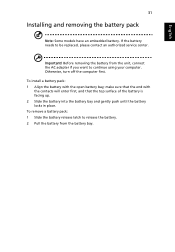
... contacts will enter first, and that the end with the open battery bay; English 31 Installing and removing the battery pack Note: Some models have an embedded battery. Before removing the battery from the battery bay. To remove a battery pack: 1 Slide the battery release latch to release the battery. 2 Pull the battery from the unit, connect the AC adapter if you want...
... contacts will enter first, and that the end with the open battery bay; English 31 Installing and removing the battery pack Note: Some models have an embedded battery. Before removing the battery from the battery bay. To remove a battery pack: 1 Slide the battery release latch to release the battery. 2 Pull the battery from the unit, connect the AC adapter if you want...
User Manual
Page 51
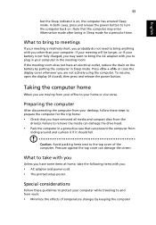
...mode. English 33 but the Sleep indicator is on . If your meeting room does not have an electrical outlet, reduce the drain on the battery by keeping the computer Press + or close the display cover whenever you are not actively using the computer. Failure to the top cover of ...the computer. Caution: Avoid packing items next to remove the media can damage the drive head. • Pack the computer in your home or vice versa. What to plug in a protective case that...
...mode. English 33 but the Sleep indicator is on . If your meeting room does not have an electrical outlet, reduce the drain on the battery by keeping the computer Press + or close the display cover whenever you are not actively using the computer. Failure to the top cover of ...the computer. Caution: Avoid packing items next to remove the media can damage the drive head. • Pack the computer in your home or vice versa. What to plug in a protective case that...
User Manual
Page 60
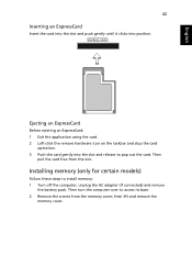
...slot. Then turn the computer over to install memory: 1 Turn off the computer, unplug the AC adapter (if connected) and remove the battery pack. then lift and remove the memory cover. English 42 Inserting an ExpressCard Insert the card into the slot and push gently until it clicks into the slot... to pop out the card. EXPRESS CARD Ejecting an ExpressCard Before ejecting an ExpressCard: 1 Exit the application using the card. 2 Left-click the remove hardware icon on the taskbar and stop the card operation. 3 Push the card gently into position. Then pull the card free from the memory cover...
...slot. Then turn the computer over to install memory: 1 Turn off the computer, unplug the AC adapter (if connected) and remove the battery pack. then lift and remove the memory cover. English 42 Inserting an ExpressCard Insert the card into the slot and push gently until it clicks into the slot... to pop out the card. EXPRESS CARD Ejecting an ExpressCard Before ejecting an ExpressCard: 1 Exit the application using the card. 2 Left-click the remove hardware icon on the taskbar and stop the card operation. 3 Push the card gently into position. Then pull the card free from the memory cover...
User Manual
Page 67
I turned on the battery, it may be too low. Check the following: • If you are using on the power, but the computer does not start or boot up. Remove or replace it is not lit, no power is being supplied to adjust the volume. • If headphones, earphones or external ...Sleep indicator is lit, the computer is in the external USB floppy drive? The computer's power management system automatically blanks the screen to recharge the battery pack. • Make sure that may be muted. Press the display toggle hotkey + to toggle the display back to turn the display back on...
I turned on the battery, it may be too low. Check the following: • If you are using on the power, but the computer does not start or boot up. Remove or replace it is not lit, no power is being supplied to adjust the volume. • If headphones, earphones or external ...Sleep indicator is lit, the computer is in the external USB floppy drive? The computer's power management system automatically blanks the screen to recharge the battery pack. • Make sure that may be muted. Press the display toggle hotkey + to toggle the display back to turn the display back on...
Service Guide
Page 7
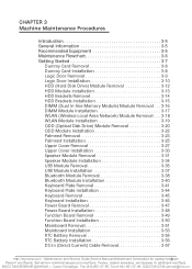
... USB Module Installation 3-37 Bluetooth Module Removal 3-38 Bluetooth Module Installation 3-40 Keyboard Plate Removal 3-41 Keyboard Plate Installation 3-44 Keyboard Removal 3-45 Keyboard Installation 3-46 Power Board Removal 3-47 Power Board Installation 3-48 Function Board Removal 3-49 Function Board Installation 3-50 Mainboard Removal 3-51 Mainboard Installation 3-53 RTC Battery Removal 3-55 RTC Battery Installation 3-56 DC-In (Direct...
... USB Module Installation 3-37 Bluetooth Module Removal 3-38 Bluetooth Module Installation 3-40 Keyboard Plate Removal 3-41 Keyboard Plate Installation 3-44 Keyboard Removal 3-45 Keyboard Installation 3-46 Power Board Removal 3-47 Power Board Installation 3-48 Function Board Removal 3-49 Function Board Installation 3-50 Mainboard Removal 3-51 Mainboard Installation 3-53 RTC Battery Removal 3-55 RTC Battery Installation 3-56 DC-In (Direct...
Service Guide
Page 8
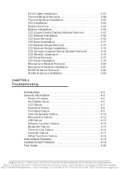
[email protected] DC-IN Cable Installation 3-57 Thermal Module Removal 3-58 Thermal Module Installation 3-60 CPU Installation 3-63 Battery Removal 3-64 Battery Installation 3-66 LCD (Liquid Crystal Display) Module Removal 3-67 LCD Module Installation 3-68 LCD Bezel Removal 3-69 LCD Bezel Installation 3-71 LCD Module Hinges Removal 3-73 LCD Module Hinges Installation 3-74 CCD (Charge-Coupled...
[email protected] DC-IN Cable Installation 3-57 Thermal Module Removal 3-58 Thermal Module Installation 3-60 CPU Installation 3-63 Battery Removal 3-64 Battery Installation 3-66 LCD (Liquid Crystal Display) Module Removal 3-67 LCD Module Installation 3-68 LCD Bezel Removal 3-69 LCD Bezel Installation 3-71 LCD Module Hinges Removal 3-73 LCD Module Hinges Installation 3-74 CCD (Charge-Coupled...

Service Guide
Page 23
...Front View Table 1-2. Only one card can operate at any given time. 2 Battery indicator Indicates the computer's battery status. Blue: Fully charged Amber: Charging On battery power: Blue: >30% battery charge remaining Amber: Remaining charge is turned off. button Plugged in -1 card ...reader Accepts Secure Digital (SD), MultiMediaCard (MMC), Memory Stick PRO (MS PRO), xD-Picture Card (xD). NOTE: Push to remove/install the card...
...Front View Table 1-2. Only one card can operate at any given time. 2 Battery indicator Indicates the computer's battery status. Blue: Fully charged Amber: Charging On battery power: Blue: >30% battery charge remaining Amber: Remaining charge is turned off. button Plugged in -1 card ...reader Accepts Secure Digital (SD), MultiMediaCard (MMC), Memory Stick PRO (MS PRO), xD-Picture Card (xD). NOTE: Push to remove/install the card...

Service Guide
Page 28
Base View No Icon Item 1 Battery reset pinhole Description Insert a paperclip into the hole to reset the computer (simulates removing and reinstalling the battery). Base View Table 1-6. Base View 0 1 Figure 1-6. Maintenance and Service Guide,ServicHeaMrdawnuaarle,MSoptheecribfiocaartdioSncsheamndatiCcsofnofrigLuarpatotipo/nostebook 812)951-37-99, Тел.8-921-951-37-99, ICQ:573812745,[email protected] ht1tp-1:/8/mycomp.su/x/ -
Base View No Icon Item 1 Battery reset pinhole Description Insert a paperclip into the hole to reset the computer (simulates removing and reinstalling the battery). Base View Table 1-6. Base View 0 1 Figure 1-6. Maintenance and Service Guide,ServicHeaMrdawnuaarle,MSoptheecribfiocaartdioSncsheamndatiCcsofnofrigLuarpatotipo/nostebook 812)951-37-99, Тел.8-921-951-37-99, ICQ:573812745,[email protected] ht1tp-1:/8/mycomp.su/x/ -

Service Guide
Page 86
... USB Module Installation 3-37 Bluetooth Module Removal 3-38 Bluetooth Module Installation 3-40 Keyboard Plate Removal 3-41 Keyboard Plate Installation 3-44 Keyboard Removal 3-45 Keyboard Installation 3-46 Power Board Removal 3-47 Power Board Installation 3-48 Function Board Removal 3-49 Function Board Installation 3-50 Mainboard Removal 3-51 Mainboard Installation 3-53 RTC Battery Removal 3-55 RTC Battery Installation 3-56 DC-In (Direct...
... USB Module Installation 3-37 Bluetooth Module Removal 3-38 Bluetooth Module Installation 3-40 Keyboard Plate Removal 3-41 Keyboard Plate Installation 3-44 Keyboard Removal 3-45 Keyboard Installation 3-46 Power Board Removal 3-47 Power Board Installation 3-48 Function Board Removal 3-49 Function Board Installation 3-50 Mainboard Removal 3-51 Mainboard Installation 3-53 RTC Battery Removal 3-55 RTC Battery Installation 3-56 DC-In (Direct...

Service Guide
Page 87
...)951-37-99, Тел.8-921-951-37-99, ICQ:573812745,[email protected] Battery Removal 3-64 Battery Installation 3-66 LCD (Liquid Crystal Display) Module Removal 3-67 LCD Module Installation 3-68 LCD Bezel Removal 3-69 LCD Bezel Installation 3-71 LCD Module Hinges Removal 3-73 LCD Module Hinges Installation 3-74 CCD (Charge-Coupled Device) Module...
...)951-37-99, Тел.8-921-951-37-99, ICQ:573812745,[email protected] Battery Removal 3-64 Battery Installation 3-66 LCD (Liquid Crystal Display) Module Removal 3-67 LCD Module Installation 3-68 LCD Bezel Removal 3-69 LCD Bezel Installation 3-71 LCD Module Hinges Removal 3-73 LCD Module Hinges Installation 3-74 CCD (Charge-Coupled Device) Module...

Service Guide
Page 136
Lower Cover Overview with Mainboard 7. Remove five (5) screws (H) from mainboard connector. 4. Disconnect HDD cable (B) from lower cover. (Figure 3-62) J H G H Figure 3-62. Disconnect microphone cable (F) from mainboard connector. 10. Disconnect battery cable (G) from mainboard connector. 9. Turn computer to show top of upper cover. (Figure 3-61) E F G Figure 3-61. Mainboard Screws ht3tp-5:/2/mycomp.su/x/ - Disconnect Bluetooth...
Lower Cover Overview with Mainboard 7. Remove five (5) screws (H) from mainboard connector. 4. Disconnect HDD cable (B) from lower cover. (Figure 3-62) J H G H Figure 3-62. Disconnect microphone cable (F) from mainboard connector. 10. Disconnect battery cable (G) from mainboard connector. 9. Turn computer to show top of upper cover. (Figure 3-61) E F G Figure 3-61. Mainboard Screws ht3tp-5:/2/mycomp.su/x/ - Disconnect Bluetooth...

Service Guide
Page 137
... lower cover. 4. Install Upper Cover. Pull side (L) of mainboard are set in image. 3. Remove mainboard from lower cover. 14. Mainboard Installation 0 1. Use caution when removing mainboard. Removing Mainboard 13. Connect LVDS cable (E) to mainboard connector. 13. Connect HDD cable (B) to mainboard ...HDMI, USB, RJ45) on lower cover as shown in upper cover slot and guides. (Figure 3-62) 5. Connect battery cable (G) to mainboard connector. 11. Remove DC-In connector (J) and cable from upper cover slot and guides. 12. Lift mainboard until clear of lower cover....
... lower cover. 4. Install Upper Cover. Pull side (L) of mainboard are set in image. 3. Remove mainboard from lower cover. 14. Mainboard Installation 0 1. Use caution when removing mainboard. Removing Mainboard 13. Connect LVDS cable (E) to mainboard connector. 13. Connect HDD cable (B) to mainboard ...HDMI, USB, RJ45) on lower cover as shown in upper cover slot and guides. (Figure 3-62) 5. Connect battery cable (G) to mainboard connector. 11. Remove DC-In connector (J) and cable from upper cover slot and guides. 12. Lift mainboard until clear of lower cover....

Service Guide
Page 139
htMtpa:/c/hminyecoMmapin.steun/xa/n-cMeaPinrotecneadnucresand Service Guide,Service Manual,Motherboard Schematics for battery (Figure 3-64) disposal. Locate RTC battery (A) on mainboard. (Figure 3-64) 0 A Figure 3-64. B Figure 3-65. Mainboard Bottom Overview with RTC Battery 2. RTC Battery Removal + IMPORTANT: Follow local regulations for Lapto3p-/5n5otebook 812)951-37-99, Тел.8-921-951-37-99, ICQ:573812745,[email protected] Remove battery from mainboard connector (B) as shown in Figure 3-65. RTC Battery Removal Prerequisite: Mainboard Removal 1.
htMtpa:/c/hminyecoMmapin.steun/xa/n-cMeaPinrotecneadnucresand Service Guide,Service Manual,Motherboard Schematics for battery (Figure 3-64) disposal. Locate RTC battery (A) on mainboard. (Figure 3-64) 0 A Figure 3-64. B Figure 3-65. Mainboard Bottom Overview with RTC Battery 2. RTC Battery Removal + IMPORTANT: Follow local regulations for Lapto3p-/5n5otebook 812)951-37-99, Тел.8-921-951-37-99, ICQ:573812745,[email protected] Remove battery from mainboard connector (B) as shown in Figure 3-65. RTC Battery Removal Prerequisite: Mainboard Removal 1.

Service Guide
Page 141
...Install mainboard. Locate DC-In cable (A) on mainboard. (Figure 3-66) A 0 A Figure 3-66. Mainboard Bottom Overview with RTC Battery 2. DC-IN Cable Installation 0 1. htMtpa:/c/hminyecoMmapin.steun/xa/n-cMeaPinrotecneadnucresand Service Guide,Service Manual,Motherboard Schematics for Lapto3p-/5n7otebook 812)951-37-...99, Тел.8-921-951-37-99, ICQ:573812745,[email protected] Remove cable from mainboard connector. 3. DC-In (Direct Current) Cable Removal Prerequisite: Mainboard Removal 1. Install and connect DC-in cable to mainboard connector. (Figure 3-66) 2.
...Install mainboard. Locate DC-In cable (A) on mainboard. (Figure 3-66) A 0 A Figure 3-66. Mainboard Bottom Overview with RTC Battery 2. DC-IN Cable Installation 0 1. htMtpa:/c/hminyecoMmapin.steun/xa/n-cMeaPinrotecneadnucresand Service Guide,Service Manual,Motherboard Schematics for Lapto3p-/5n7otebook 812)951-37-...99, Тел.8-921-951-37-99, ICQ:573812745,[email protected] Remove cable from mainboard connector. 3. DC-In (Direct Current) Cable Removal Prerequisite: Mainboard Removal 1. Install and connect DC-in cable to mainboard connector. (Figure 3-66) 2.

Service Guide
Page 148
Battery Removal 0 Prerequisite: Mainboard Removal 1. Locate battery and holder (A) on lower cover. (Figure 3-75) A Figure 3-75. Battery Holder with Battery and Holder 2. Maintenance and Service Guide,Service Manual,MMoathcehribnoeaMrdaSinchteenmaantices fPoroLcaepdtoupr/enostebook 812)951-37-99, Тел.8-921-951-37-99, ICQ:573812745,[email protected] Lower Cover Overview with LVDS and Microphone Cables ht3tp-6:/4/mycomp.su/x/ - Remove LVDS cable (B) from battery holder guides. (Figure 3-76) B C Figure 3-76.
Battery Removal 0 Prerequisite: Mainboard Removal 1. Locate battery and holder (A) on lower cover. (Figure 3-75) A Figure 3-75. Battery Holder with Battery and Holder 2. Maintenance and Service Guide,Service Manual,MMoathcehribnoeaMrdaSinchteenmaantices fPoroLcaepdtoupr/enostebook 812)951-37-99, Тел.8-921-951-37-99, ICQ:573812745,[email protected] Lower Cover Overview with LVDS and Microphone Cables ht3tp-6:/4/mycomp.su/x/ - Remove LVDS cable (B) from battery holder guides. (Figure 3-76) B C Figure 3-76.

Service Guide
Page 151
...-99, Тел.8-921-951-37-99, ICQ:573812745,[email protected] WLAN Module Antenna Cables 2. LCD (Liquid Crystal Display) Module Removal 0 Prerequisite: Battery Removal 1. LCD Module Hinge Screws 3. Remove LCD module from LCD module hinges. (Figure 3-80) B B Figure 3-80. Remove WLAN antenna cables (A) from guides on lower cover. (Figure 3-79) A Figure 3-79.
...-99, Тел.8-921-951-37-99, ICQ:573812745,[email protected] WLAN Module Antenna Cables 2. LCD (Liquid Crystal Display) Module Removal 0 Prerequisite: Battery Removal 1. LCD Module Hinge Screws 3. Remove LCD module from LCD module hinges. (Figure 3-80) B B Figure 3-80. Remove WLAN antenna cables (A) from guides on lower cover. (Figure 3-79) A Figure 3-79.

