
Aspire 3680/5570/5580 Service Guide
Page 79
... degree as shown. 8. Remove the wireless LAN card from the main board then disconnect the modem board cable. Detach the modem board from the socket. 7. Removing the LCD Module (including Keyboard) 1. Removing the ODD Module 1. Push the ODD module outwards then remove it. Carefully detach the keyboard cover from the main unit...
... degree as shown. 8. Remove the wireless LAN card from the main board then disconnect the modem board cable. Detach the modem board from the socket. 7. Removing the LCD Module (including Keyboard) 1. Removing the ODD Module 1. Push the ODD module outwards then remove it. Carefully detach the keyboard cover from the main unit...
Aspire 3680/5570/5580 Service Guide
Page 80
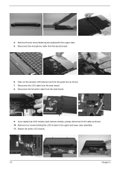
Remove the two screw fastening the keyboard to the upper and lower case assembly. 11. If you laptop has CCD module (web camera module), please disconnect CCD cable as shown. 7. Disconnect the microphone cable from the main board. . 9. Disconnect the lid switch cable from the launch board. 6. 4. Disconnect the LCD cable from the guide-line as shown. 10. Remove four screws holding the LCD module to the upper case. 5. Take out the wireless LAN antenna set from the main board. 8. Detach the entire LCD module. 72 Chapter 3
Remove the two screw fastening the keyboard to the upper and lower case assembly. 11. If you laptop has CCD module (web camera module), please disconnect CCD cable as shown. 7. Disconnect the microphone cable from the main board. . 9. Disconnect the lid switch cable from the launch board. 6. 4. Disconnect the LCD cable from the guide-line as shown. 10. Remove four screws holding the LCD module to the upper case. 5. Take out the wireless LAN antenna set from the main board. 8. Detach the entire LCD module. 72 Chapter 3

Aspire 3680/5570/5580 Service Guide
Page 83
.... 10. Take out the LCD assembly from the LCD module. 4. Disassembling the LCD Module (with video camera) 1. Then detach the LCD bezel from the LCD cover. 8. Remove five screws holding the CCD module. 9. Remove the screws holding the LCD assembly to the LCD cover. 7. Disconnect the CCD cable from the LCD cover and disconnect the LVDS cable as shown. 2. Remove...
.... 10. Take out the LCD assembly from the LCD module. 4. Disassembling the LCD Module (with video camera) 1. Then detach the LCD bezel from the LCD cover. 8. Remove five screws holding the CCD module. 9. Remove the screws holding the LCD assembly to the LCD cover. 7. Disconnect the CCD cable from the LCD cover and disconnect the LVDS cable as shown. 2. Remove...

Aspire 3680/5570/5580 Service Guide
Page 84
Then remove the left LCD bracket from the LCD. 76 Chapter 3 Disconnect the LCD cable from the LCD. 14. 13. Tear off the mylar fastening the LCD cable. 15.
Then remove the left LCD bracket from the LCD. 76 Chapter 3 Disconnect the LCD cable from the LCD. 14. 13. Tear off the mylar fastening the LCD cable. 15.

Aspire 3680/5570/5580 Service Guide
Page 95
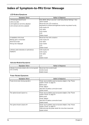
Reconnect the DIMM. Power source (battery pack and power adapter). LCD inverter ID LCD cable LCD inverter LCD System board No beep, power-on indicator turns on and a blinking cursor shown on LCD during POST but system runs correctly. Ensure every connector is blank. Speaker System board Chapter 4 87 System board. No beep, power-on indicator turns...
Reconnect the DIMM. Power source (battery pack and power adapter). LCD inverter ID LCD cable LCD inverter LCD System board No beep, power-on indicator turns on and a blinking cursor shown on LCD during POST but system runs correctly. Ensure every connector is blank. Speaker System board Chapter 4 87 System board. No beep, power-on indicator turns...
Aspire 3680/5570/5580 Service Guide
Page 100
... switch for more than 4 seconds. System board 92 Chapter 4 LCD inverter ID LCD cable LCD inverter LCD System board Reconnect the LCD connector LCD inverter ID LCD cable LCD inverter LCD System board LCD inverter ID LCD inverter LCD cable LCD System board Indicator-Related Symptoms Symptom / Error Action in Sequence Indicator...and power adapter). Keyboard (if contrast and brightness function key doesn't work LCD is too dark LCD brightness cannot be adjusted LCD contrast cannot be adjusted Unreadable LCD screen Missing pels in Sequence Power source (battery pack and power adapter). See...
... switch for more than 4 seconds. System board 92 Chapter 4 LCD inverter ID LCD cable LCD inverter LCD System board Reconnect the LCD connector LCD inverter ID LCD cable LCD inverter LCD System board LCD inverter ID LCD inverter LCD cable LCD System board Indicator-Related Symptoms Symptom / Error Action in Sequence Indicator...and power adapter). Keyboard (if contrast and brightness function key doesn't work LCD is too dark LCD brightness cannot be adjusted LCD contrast cannot be adjusted Unreadable LCD screen Missing pels in Sequence Power source (battery pack and power adapter). See...
Aspire 3680/5570/5580 Service Guide
Page 102
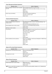
... System board NOTE: If you cannot find a symptom or an error in Sequence Reconnect the keyboard cable. USB does not work . Keyboard System board Reconnect touchpad cable. Touchpad board System board Modem-Related Symptoms Symptom / Error Action in the "Onboard Devices Configuration" ...of BIOS Setup Utility is set to Enabled. Press Fn+F5, LCD/CRT/Both display switching System board System board ...
... System board NOTE: If you cannot find a symptom or an error in Sequence Reconnect the keyboard cable. USB does not work . Keyboard System board Reconnect touchpad cable. Touchpad board System board Modem-Related Symptoms Symptom / Error Action in the "Onboard Devices Configuration" ...of BIOS Setup Utility is set to Enabled. Press Fn+F5, LCD/CRT/Both display switching System board System board ...

Aspire 3680/5570/5580 Service Guide
Page 119
...Acer Part No. 25.TCZV1.001 Chapter 6 LCD/INVERTER CABLE 14.1" WXGA 50.TCZV1.004 LCD BRACKET RIGHT Note: Right bracket is the upper one. 33.TB1V1.003 LCD BRACKET LEFT Note: Left bracket is the lower one 33.TB1V1.004 LCD PANEL 14.1" W/HINGE LCD BEZEL 14.1" W/LOGO HINGE PACK LEFT/RIGHT 60.AA6V1.004(Aspire...) 60.TB2V1.004(TravelMate) 60.TCZV1.005(TravelMate) 60.TB2V1.005 6K.TB2V1.001 LCD 14.1" WXGA AU B141EW01 V.1 NONE GLARE LCD 14" WXGA SAMSUNG LTN141W1-L01 NONE GLARE LCD 14.1" WXGA LG LP141WX1TL02 NONE GLARE LCD 14.1" WXGA QDI QD14TL01-03 NONE ...
...Acer Part No. 25.TCZV1.001 Chapter 6 LCD/INVERTER CABLE 14.1" WXGA 50.TCZV1.004 LCD BRACKET RIGHT Note: Right bracket is the upper one. 33.TB1V1.003 LCD BRACKET LEFT Note: Left bracket is the lower one 33.TB1V1.004 LCD PANEL 14.1" W/HINGE LCD BEZEL 14.1" W/LOGO HINGE PACK LEFT/RIGHT 60.AA6V1.004(Aspire...) 60.TB2V1.004(TravelMate) 60.TCZV1.005(TravelMate) 60.TB2V1.005 6K.TB2V1.001 LCD 14.1" WXGA AU B141EW01 V.1 NONE GLARE LCD 14" WXGA SAMSUNG LTN141W1-L01 NONE GLARE LCD 14.1" WXGA LG LP141WX1TL02 NONE GLARE LCD 14.1" WXGA QDI QD14TL01-03 NONE ...


