Aspire 5220/5520/5520G User's Guide
Page 40
Note: Do not cover or obstruct the opening of the fan. English 20 Base view 1 2 6 3 4 5 # Icon Item 1 Battery bay Description Houses the computer's battery pack. 2 Battery release latch Releases the battery for removal. 3 Battery lock Locks the battery in position. 4 Memory compartment Houses the computer's main memory. 5 Hard disk bay Houses the computer's hard disk (secured with screws). 6 Ventilation slots and Enable the computer to stay cool, even after cooling fan prolonged use.
Note: Do not cover or obstruct the opening of the fan. English 20 Base view 1 2 6 3 4 5 # Icon Item 1 Battery bay Description Houses the computer's battery pack. 2 Battery release latch Releases the battery for removal. 3 Battery lock Locks the battery in position. 4 Memory compartment Houses the computer's main memory. 5 Hard disk bay Houses the computer's hard disk (secured with screws). 6 Ventilation slots and Enable the computer to stay cool, even after cooling fan prolonged use.

Aspire 5220/5520/5520G Service Guide
Page 18
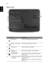
cooling fan Note: Do not cover or obstruct the opening of the fan. The front panel indicators are visible even when the computer cover is closed. 12 Chapter 1 Indicators The computer has several easy-to stay cool, even after prolonged use. Base view # Item Description 1 Battery bay Houses the computer's battery pack. 2 Battery release latch Releases the battery for removal. 3 Battery lock Locks the battery in position. 4 Hard disk bay Houses the computer's hard disk (secured with screws) 5 Ventilation slots and Enable the computer to -read status indicators.
cooling fan Note: Do not cover or obstruct the opening of the fan. The front panel indicators are visible even when the computer cover is closed. 12 Chapter 1 Indicators The computer has several easy-to stay cool, even after prolonged use. Base view # Item Description 1 Battery bay Houses the computer's battery pack. 2 Battery release latch Releases the battery for removal. 3 Battery lock Locks the battery in position. 4 Hard disk bay Houses the computer's hard disk (secured with screws) 5 Ventilation slots and Enable the computer to -read status indicators.
Aspire 5220/5520/5520G Service Guide
Page 37
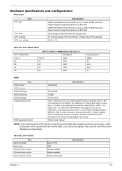
...-MV (Single chip) S1 Socket package CPU with 638-pin Lindless Micro PGA package 0.944~1.3V CPU Fan True Value Table CPU Temperature Core 0 86 88 91 95 TEST Condition: 35W@Ambient 35 degree C Fan Speed Core 1 (rpm) 86 3700 88 3450 91 3150 95 2800 Acoustic Level (dBA) 39 36.5 34...
...-MV (Single chip) S1 Socket package CPU with 638-pin Lindless Micro PGA package 0.944~1.3V CPU Fan True Value Table CPU Temperature Core 0 86 88 91 95 TEST Condition: 35W@Ambient 35 degree C Fan Speed Core 1 (rpm) 86 3700 88 3450 91 3150 95 2800 Acoustic Level (dBA) 39 36.5 34...

Aspire 5220/5520/5520G Service Guide
Page 63
... (for AS models) Lower Case F*1 Main Board F*2 Speaker Set F*2 Media Board (for AS models) F*1 Touchpad Bracket Touchpad Touchpad FFC Chapter 3 70 Start Battery Pack B*1 D*1 System Fan B*4 Thermal Module F*1 ODD Module CPU D*5 F*1 Thermal Door Memory Lower Case Assembly F*1 Mimi Cover F*2 HDD Door H*4 HDD Bracket HDD Middle Cover F*2 Keyboard C*2 LCD hinges to logic...
... (for AS models) Lower Case F*1 Main Board F*2 Speaker Set F*2 Media Board (for AS models) F*1 Touchpad Bracket Touchpad Touchpad FFC Chapter 3 70 Start Battery Pack B*1 D*1 System Fan B*4 Thermal Module F*1 ODD Module CPU D*5 F*1 Thermal Door Memory Lower Case Assembly F*1 Mimi Cover F*2 HDD Door H*4 HDD Bracket HDD Middle Cover F*2 Keyboard C*2 LCD hinges to logic...

Aspire 5220/5520/5520G Service Guide
Page 66
Detach the HDD cover from the main unit. 3. Remove the four screws holding the thermal cover. 2. Pull the tab to remove the HDD module in the direction of the arrow. Removing the Memory 1. Detach the thermal cover from the main unit. 3. Remove the two screws fastening the HDD cover. 2. Removing the HDD Module/Memory/Wireless LAN Card/Modem Card/ System Fan/Thermal Modules/VGA Board/CPU/Keyboard and the LCD Module Removing the HDD Module 1. Pop out the memory from the DIMM socket then remove it (If the notebook has two memory, then repeat this step). 73 Chapter 3
Detach the HDD cover from the main unit. 3. Remove the four screws holding the thermal cover. 2. Pull the tab to remove the HDD module in the direction of the arrow. Removing the Memory 1. Detach the thermal cover from the main unit. 3. Remove the two screws fastening the HDD cover. 2. Removing the HDD Module/Memory/Wireless LAN Card/Modem Card/ System Fan/Thermal Modules/VGA Board/CPU/Keyboard and the LCD Module Removing the HDD Module 1. Pop out the memory from the DIMM socket then remove it (If the notebook has two memory, then repeat this step). 73 Chapter 3

Aspire 5220/5520/5520G Service Guide
Page 68
Remove the three screws holding the CPU thermal module. 4. Use a flat screwdriver to release the CPU lock (Turn counter clock-wire). 6. Remove the CPU from the main board. 2. Disconnect the fan cable from the CPU socket carefully. 75 Chapter 3 Then detach the CPU thermal module as shown. 5. Remove the four spring screws holding the system fan. 3. Removing the System Fan/Thermal Modules/VGA Board and CPU 1.
Remove the three screws holding the CPU thermal module. 4. Use a flat screwdriver to release the CPU lock (Turn counter clock-wire). 6. Remove the CPU from the main board. 2. Disconnect the fan cable from the CPU socket carefully. 75 Chapter 3 Then detach the CPU thermal module as shown. 5. Remove the four spring screws holding the system fan. 3. Removing the System Fan/Thermal Modules/VGA Board and CPU 1.

Aspire 5220/5520/5520G Service Guide
Page 108
....006 47.AHE02.007 47.AHE02.008 40.AHE02.001 TBD 47.AHE02.002 47.AHE02.003 47.AHE02.004 Chapter 6 Part Name and Description Acer Part No. MEMORY 1GB DDRII 667 NANYA NT1GT64U8HB0BN-3C KN.1GB03.014 MEMORY 1GB DDRII 667 SAMSUNG KN.1GB0B.011 M470T2953EZ3-CE6 MEMORY 1GB DDRII... 667 HYNIX HYMP512S64CP8-Y5 KN.1GB0G.006 FAN 23.AHE02.001 CPU THERMAL MODULE 60.AHE02.009 SPEAKER ACCESSORY MISCELLANEOUS 100 VGA THERMAL (M71M)-DIS 60.AHE02.010 SPEAKER R 15.4 SPEAKER L 15.4 23...
....006 47.AHE02.007 47.AHE02.008 40.AHE02.001 TBD 47.AHE02.002 47.AHE02.003 47.AHE02.004 Chapter 6 Part Name and Description Acer Part No. MEMORY 1GB DDRII 667 NANYA NT1GT64U8HB0BN-3C KN.1GB03.014 MEMORY 1GB DDRII 667 SAMSUNG KN.1GB0B.011 M470T2953EZ3-CE6 MEMORY 1GB DDRII... 667 HYNIX HYMP512S64CP8-Y5 KN.1GB0G.006 FAN 23.AHE02.001 CPU THERMAL MODULE 60.AHE02.009 SPEAKER ACCESSORY MISCELLANEOUS 100 VGA THERMAL (M71M)-DIS 60.AHE02.010 SPEAKER R 15.4 SPEAKER L 15.4 23...


