Quick Start Guide
Page 11
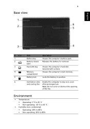
Locks the battery in position. Ventilation slots and cooling fan Enable the computer to 80% Houses the computer's hard disk (secured with screws). Houses the computer's main memory. Environment • Temperature: • Operating: 5 °C to ... release latch Hard disk bay Memory compartment Battery lock Description Houses the computer's battery pack. Note: Do not cover or obstruct the opening of the fan.
Locks the battery in position. Ventilation slots and cooling fan Enable the computer to 80% Houses the computer's hard disk (secured with screws). Houses the computer's main memory. Environment • Temperature: • Operating: 5 °C to ... release latch Hard disk bay Memory compartment Battery lock Description Houses the computer's battery pack. Note: Do not cover or obstruct the opening of the fan.
Service Guide
Page 19
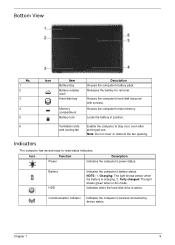
Note: Do not cover or obstruct the fan opening. NOTE: 1. Fully charged: The light shows green when in position. 6 Ventilation slots Enable the computer to -read status indicators. Communication indicator Indicates the computer's ...wireless connectivitoy device status. Locks the battery in AC mode. Indicators The computer has several easy-to stay cool, even after and cooling fan prolonged use. Icon Function Power Description Indicates the computer's power status. Charging: The light shows amber when the battery is active. Battery HDD Indicates the...
Note: Do not cover or obstruct the fan opening. NOTE: 1. Fully charged: The light shows green when in position. 6 Ventilation slots Enable the computer to -read status indicators. Communication indicator Indicates the computer's ...wireless connectivitoy device status. Locks the battery in AC mode. Indicators The computer has several easy-to stay cool, even after and cooling fan prolonged use. Icon Function Power Description Indicates the computer's power status. Charging: The light shows amber when the battery is active. Battery HDD Indicates the...
Service Guide
Page 24
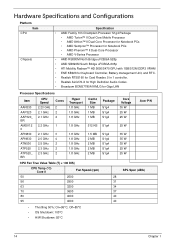
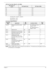
... S1g4 S1g4 S1g4 S1g4 S1g4 S1g4 S1g4 S1g4 Core Voltage 35 W 25 W 25 W 25 W 35 W 35 W 35 W 25 W 25 W Acer P/N CPU Fan True Value Table (Tj = 100 DIS) CPU Temp (°C) Core 0 Fan Speed (rpm) 50 2500 56 2900 63 3200 70 3600 80 4000 95 4000 SPL Spec (dBA) 28 31 34...
... S1g4 S1g4 S1g4 S1g4 S1g4 S1g4 S1g4 S1g4 Core Voltage 35 W 25 W 25 W 25 W 35 W 35 W 35 W 25 W 25 W Acer P/N CPU Fan True Value Table (Tj = 100 DIS) CPU Temp (°C) Core 0 Fan Speed (rpm) 50 2500 56 2900 63 3200 70 3600 80 4000 95 4000 SPL Spec (dBA) 28 31 34...
Service Guide
Page 25
... Specifications Operation Mode Application SPL dBA Fan off Windows Idle (HDD random N/A seek) Fan 1 Windows Idle 28 Fan 2 Windows Idle, HDD spinning 31 Fan 3 Play Movie (read from HDD), 34 Play TV (TV tuner sku) Fan 4 3DMark06,Prime95, 37 Prime95+Play TV(TV tuner sku), acer screen saver, HDD spinning Fan 5 TAT100% or 40 Thermanow100%,3DMark06, at...
... Specifications Operation Mode Application SPL dBA Fan off Windows Idle (HDD random N/A seek) Fan 1 Windows Idle 28 Fan 2 Windows Idle, HDD spinning 31 Fan 3 Play Movie (read from HDD), 34 Play TV (TV tuner sku) Fan 4 3DMark06,Prime95, 37 Prime95+Play TV(TV tuner sku), acer screen saver, HDD spinning Fan 5 TAT100% or 40 Thermanow100%,3DMark06, at...

Service Guide
Page 91
Removing the Thermal Module 1. Disconnect the fan cable. 3. Remove the four (4) securing screws (in reverse numerical order from screw 4 to 1), then the two (2) screws on page 61. 2. See "Removing the Upper Cover" on the GPU. 2 1 4 3 Step Thermal Module Size M2.5*3.2 GPU Quantity 4 2 Screw Type Chapter 3 81
Removing the Thermal Module 1. Disconnect the fan cable. 3. Remove the four (4) securing screws (in reverse numerical order from screw 4 to 1), then the two (2) screws on page 61. 2. See "Removing the Upper Cover" on the GPU. 2 1 4 3 Step Thermal Module Size M2.5*3.2 GPU Quantity 4 2 Screw Type Chapter 3 81

Service Guide
Page 121
Chapter 3 111 5. Connect the fan cable.
Chapter 3 111 5. Connect the fan cable.
Service Guide
Page 148
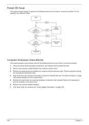
... (see "Online Support Information" on page 195. 138 Chapter 4 Check the power cable is still not resolved, see "Thermal Unit Failure" on page 148) and fan airways are not necessary to boot the computer to the failure point. 6. If the Issue is properly connected to the computer and the electrical outlet...
... (see "Online Support Information" on page 195. 138 Chapter 4 Check the power cable is still not resolved, see "Thermal Unit Failure" on page 148) and fan airways are not necessary to boot the computer to the failure point. 6. If the Issue is properly connected to the computer and the electrical outlet...
Service Guide
Page 149
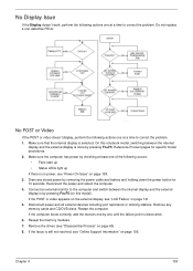
... point is discovered. 6. Do not replace a non-defective FRUs: No POST or Video If the POST or video doesn't display, perform the following occurs: • Fans start up • Status LEDs light up If there is no power, see "LCD Failure" on page 45). 8. Reseat the memory modules. 7.
... point is discovered. 6. Do not replace a non-defective FRUs: No POST or Video If the POST or video doesn't display, perform the following occurs: • Fans start up • Status LEDs light up If there is no power, see "LCD Failure" on page 45). 8. Reseat the memory modules. 7.


