
Service Guide
Page 7
...Acer Notebook tour 5 Front View 5 Left View 6 Right View 7 Rear View 7 Bottom View 7 Indicators 8 TouchPad Basics 9 Using the Keyboard 10 Lock Keys and embedded numeric keypad 10 Windows Keys 11 Hot Keys 12 Hardware Specifications and Configurations 13 18 System Utilities 19 BIOS Setup Utility 19 Navigating the BIOS Utility 19 TBD Intel BIOS... 20 Information 20 Main 21 Security 22 Boot 25 Exit 26 BIOS Flash Utilities 27 DOS Flash Utility 28 ...
...Acer Notebook tour 5 Front View 5 Left View 6 Right View 7 Rear View 7 Bottom View 7 Indicators 8 TouchPad Basics 9 Using the Keyboard 10 Lock Keys and embedded numeric keypad 10 Windows Keys 11 Hot Keys 12 Hardware Specifications and Configurations 13 18 System Utilities 19 BIOS Setup Utility 19 Navigating the BIOS Utility 19 TBD Intel BIOS... 20 Information 20 Main 21 Security 22 Boot 25 Exit 26 BIOS Flash Utilities 27 DOS Flash Utility 28 ...

Service Guide
Page 8
... the Dummy Cards 102 Replacing the Battery Pack 102 Troubleshooting 103 Common Problems 103 Power On Issue 104 No Display Issue 105 Random Loss of BIOS Settings 106 LCD Failure 107 VIII
... the Dummy Cards 102 Replacing the Battery Pack 102 Troubleshooting 103 Common Problems 103 Power On Issue 104 No Display Issue 105 Random Loss of BIOS Settings 106 LCD Failure 107 VIII

Service Guide
Page 9
...Top View 119 Bottom View 119 Clearing Password Check and BIOS Recovery 120 Clearing Password Check 120 BIOS Recovery by Crisis Disk 121 FRU (Field Replaceable Unit) List 123 Acer TBD Exploded Diagrams 124 LCD Assembly 124 Acer TBD FRU List 125 Screw List 125 Model Definition ...and Configuration 126 Acer TBD Series 126 Test Compatible Components 127 Microsoft®...
...Top View 119 Bottom View 119 Clearing Password Check and BIOS Recovery 120 Clearing Password Check 120 BIOS Recovery by Crisis Disk 121 FRU (Field Replaceable Unit) List 123 Acer TBD Exploded Diagrams 124 LCD Assembly 124 Acer TBD FRU List 125 Screw List 125 Model Definition ...and Configuration 126 Acer TBD Series 126 Test Compatible Components 127 Microsoft®...

Service Guide
Page 13
...BIOS user, supervisor, HDD passwords • Kensington lock slot Dimensions and weight • 342 (W) x 245 (D) x 19.4/25.4 (H) mm (13.46 x 9.64 x 0.76/0.99 inches) • 2.2 kg (4.85 lbs.) with 6-cell battery Power subsystem • ACPI 3.0 CPU power management standard: supports Standby and Hibernation power-saving modes • Acer...four cursor keys, two Windows® keys, hotkey controls, independent standard numeric keypad, international language support • Acer Programming key • Easy-launch keys: Communication® • Media control keys (printed on keyboard): play/...
...BIOS user, supervisor, HDD passwords • Kensington lock slot Dimensions and weight • 342 (W) x 245 (D) x 19.4/25.4 (H) mm (13.46 x 9.64 x 0.76/0.99 inches) • 2.2 kg (4.85 lbs.) with 6-cell battery Power subsystem • ACPI 3.0 CPU power management standard: supports Standby and Hibernation power-saving modes • Acer...four cursor keys, two Windows® keys, hotkey controls, independent standard numeric keypad, international language support • Acer Programming key • Easy-launch keys: Communication® • Media control keys (printed on keyboard): play/...

Service Guide
Page 26
... monitor (if connected) and both. Turns the speakers on and off to access most of the computer's controls like screen brightness, volume output and the BIOS utility. Increases the screen brightness. Stop playing the selected media file.
... monitor (if connected) and both. Turns the speakers on and off to access most of the computer's controls like screen brightness, volume output and the BIOS utility. Increases the screen brightness. Stop playing the selected media file.

Service Guide
Page 27
... M 540 M 620 M Cache Size 3 MB 3 MB 3 MB 3 MB 3 MB 4 MB Package PGA988 PGA988 PGA988 PGA988P PGA988 PGA988P Core Voltage 35W 35W 35W 35W 35W 35W Acer P/N KC.33001.DMP KC.35001.DMP KC.43001.DMP KC.52001.DMP KC.54001.DMP KC.62001.DMP CPU Fan True Value Table (Tj = 100... Speed (rpm) 45 2500 55 3100 65 3500 75 3900 85 4200 SPL Spec (dBA) 31 34 38 40 • OS Shutdown: 95°C • BIOS H/W Shutdown: 100°C Item BIOS vendor BIOS Version BIOS ROM type Insyde BIOS 1.00 Flash Specification Chapter 1 17
... M 540 M 620 M Cache Size 3 MB 3 MB 3 MB 3 MB 3 MB 4 MB Package PGA988 PGA988 PGA988 PGA988P PGA988 PGA988P Core Voltage 35W 35W 35W 35W 35W 35W Acer P/N KC.33001.DMP KC.35001.DMP KC.43001.DMP KC.52001.DMP KC.54001.DMP KC.62001.DMP CPU Fan True Value Table (Tj = 100... Speed (rpm) 45 2500 55 3100 65 3500 75 3900 85 4200 SPL Spec (dBA) 31 34 38 40 • OS Shutdown: 95°C • BIOS H/W Shutdown: 100°C Item BIOS vendor BIOS Version BIOS ROM type Insyde BIOS 1.00 Flash Specification Chapter 1 17

Service Guide
Page 28
.... Wireless Module Item Specification Manufacturer • Intel® WiFi Link 1000 18 Chapter 1 You may combine DIMMs with various capacities to Acer BIOS specification. • DMI utility for system control • Support SMBIOS 2.3, PCI2.2. • Refer to form other combinations. Features Item... voltage Specification • Flash ROM 4MB • Support ISIPP • Support Acer UI • Support multi-boot • Suspend to RAM (S3)/Disk (S4) • Various hot-keys for BIOS serial number configurable/asset tag • Support PXE • Support Y2K solution ...
.... Wireless Module Item Specification Manufacturer • Intel® WiFi Link 1000 18 Chapter 1 You may combine DIMMs with various capacities to Acer BIOS specification. • DMI utility for system control • Support SMBIOS 2.3, PCI2.2. • Refer to form other combinations. Features Item... voltage Specification • Flash ROM 4MB • Support ISIPP • Support Acer UI • Support multi-boot • Suspend to RAM (S3)/Disk (S4) • Various hot-keys for BIOS serial number configurable/asset tag • Support PXE • Support Y2K solution ...

Service Guide
Page 29
... • Radio Technology FHSS • Operating Frequency 2.402GHz ~ 2.480GHz • Channel Numbers 79 channels with dramatically improved thermal and electrical characteristics over -clocking without requiring BIOS support • Supports Energy Star 5.0 • Small footprint 40-pin QFN (5 x 5 mm) package with 1MHz BW • Transmitter Output Power -6~4dBm output power for 10...
... • Radio Technology FHSS • Operating Frequency 2.402GHz ~ 2.480GHz • Channel Numbers 79 channels with dramatically improved thermal and electrical characteristics over -clocking without requiring BIOS support • Supports Energy Star 5.0 • Small footprint 40-pin QFN (5 x 5 mm) package with 1MHz BW • Transmitter Output Power -6~4dBm output power for 10...

Service Guide
Page 35
...for a particular menu are in any of the menu options to go to the Exit menu. • In any changes made and exit the BIOS Setup Utility. However, if you encounter configuration problems, you may need to run Setup. If you want to change the value of screen). In ...of F12 Boot Menu is prompted on the bottom of the screen. Your computer is a hardware configuration program built into your computer's BIOS (Basic Input/ Output System). Navigating the BIOS Utility There are found in square brackets. Follow these instructions: • To choose a menu, use the left and right arrow ...
...for a particular menu are in any of the menu options to go to the Exit menu. • In any changes made and exit the BIOS Setup Utility. However, if you encounter configuration problems, you may need to run Setup. If you want to change the value of screen). In ...of F12 Boot Menu is prompted on the bottom of the screen. Your computer is a hardware configuration program built into your computer's BIOS (Basic Input/ Output System). Navigating the BIOS Utility There are found in square brackets. Follow these instructions: • To choose a menu, use the left and right arrow ...

Service Guide
Page 36
...: VGA BIOS Version: Serial Number: Asset Tag Number: Product Name: Manufacturer Name: UUID: Intel(R) Core(TM) i3 CPU 2.13GHz Hitachi HTS5450116B9A300 091204PBPB06QCK3D3EM TSSTcorp CDDVDW TS-L633C V1.00 Intel V1914 Acer M 330 F1 Help ESC Exit Select Item F5/F6 Change Values F9 ...Software Foundation (OSF) as part of the Distributed Computing Environment (DCE). 26 Chapter 2 Actual values may differ according to model. Aspire 4820T BIOS Information The Information screen displays a summary of your reference only. This field displays the serial number of the CPU. This field shows...
...: VGA BIOS Version: Serial Number: Asset Tag Number: Product Name: Manufacturer Name: UUID: Intel(R) Core(TM) i3 CPU 2.13GHz Hitachi HTS5450116B9A300 091204PBPB06QCK3D3EM TSSTcorp CDDVDW TS-L633C V1.00 Intel V1914 Acer M 330 F1 Help ESC Exit Select Item F5/F6 Change Values F9 ...Software Foundation (OSF) as part of the Distributed Computing Environment (DCE). 26 Chapter 2 Actual values may differ according to model. Aspire 4820T BIOS Information The Information screen displays a summary of your reference only. This field displays the serial number of the CPU. This field shows...

Service Guide
Page 38
... system halts. The following sub-options are the default and suggested parameter settings. Defines whether a password is set , this password protects the BIOS Setup Utility from unauthorized access. The user can not either enter the Setup menu nor change the value of parameters. When set , this... password protects the BIOS Setup Utility from unauthorized use. If you forget your dealer to change the value of parameters. When user password is required or not...
... system halts. The following sub-options are the default and suggested parameter settings. Defines whether a password is set , this password protects the BIOS Setup Utility from unauthorized access. The user can not either enter the Setup menu nor change the value of parameters. When set , this... password protects the BIOS Setup Utility from unauthorized use. If you forget your dealer to change the value of parameters. When user password is required or not...

Service Guide
Page 39
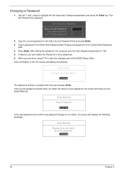
... do not appear on boot parameter. 5. Removing a Password Follow these steps as you are done, press F10 to save the changes and exit the BIOS Setup Utility. Chapter 2 29 The Set Supervisor Password box appears: Set Supervisor Password Enter New Password [ ] Confirm New Password [ ] 2. If ...Password" field. Use the ↑ and ↓ keys to "Set". 4. The password length can opt to save the changes and exit the BIOS Setup Utility. Use the ↑ and ↓ keys to "Clear". 4. The computer then sets the Supervisor Password parameter to highlight the Set ...
... do not appear on boot parameter. 5. Removing a Password Follow these steps as you are done, press F10 to save the changes and exit the BIOS Setup Utility. Chapter 2 29 The Set Supervisor Password box appears: Set Supervisor Password Enter New Password [ ] Confirm New Password [ ] 2. If ...Password" field. Use the ↑ and ↓ keys to "Set". 4. The password length can opt to save the changes and exit the BIOS Setup Utility. Use the ↑ and ↓ keys to "Clear". 4. The computer then sets the Supervisor Password parameter to highlight the Set ...
Service Guide
Page 40
... Setup Warning. Use the ↑ and ↓ keys to "Set". 5. Changing a Password 1. When you are done, press F10 to save the changes and exit the BIOS Setup Utility.
... Setup Warning. Use the ↑ and ↓ keys to "Set". 5. Changing a Password 1. When you are done, press F10 to save the changes and exit the BIOS Setup Utility.

Service Guide
Page 42
... Select SubMenu F10 Save and Exit The table below describes the parameters in this screen. Exit The Exit screen allows you made and quit the BIOS Utility.
... Select SubMenu F10 Save and Exit The table below describes the parameters in this screen. Exit The Exit screen allows you made and quit the BIOS Utility.
Service Guide
Page 43
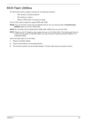
...the bootable diskette. NOTE: Please use the Flash utility. Prepare a bootable diskette. 2. Chapter 2 33 Copy the flash utilities to update the system BIOS flash ROM. NOTE: If you do not have a crisis recovery diskette at hand, then you should create a Crisis Recovery Diskette before you use the...battery pack does not contain enough power to run the Flash utility. The flash utility has auto-execution function. Fellow the steps below to finish BIOS flash, you use the Flash. Use the Flash utility to the bootable diskette. 3. NOTE: Do not install memory-related drivers (XMS, ...
...the bootable diskette. NOTE: Please use the Flash utility. Prepare a bootable diskette. 2. Chapter 2 33 Copy the flash utilities to update the system BIOS flash ROM. NOTE: If you do not have a crisis recovery diskette at hand, then you should create a Crisis Recovery Diskette before you use the...battery pack does not contain enough power to run the Flash utility. The flash utility has auto-execution function. Fellow the steps below to finish BIOS flash, you use the Flash. Use the Flash utility to the bootable diskette. 3. NOTE: Do not install memory-related drivers (XMS, ...

Service Guide
Page 44
... CDDVDW TS-L633C 3. USB CDROM : Use < > or < > to select a device, then press to move it down the list, or to move USB HDD to Update BIOS, move it up the list. Press to use the DOS Flash Utility: 1. USB HDD : 6. IDE0 : TOSHIBA MK3265GSX 2. USB FDD : 4. The flash process begins as shown... Exit 3. Network Boot : LEGACY PCI DEVICE 5. Select Boot Menu to modify the boot priority order, for example, if using USB HDD to position 1. Execute the BIOS.BAT batch file to enter the Setup Menu. 2. Press F2 during boot to update...
... CDDVDW TS-L633C 3. USB CDROM : Use < > or < > to select a device, then press to move it down the list, or to move USB HDD to Update BIOS, move it up the list. Press to use the DOS Flash Utility: 1. USB HDD : 6. IDE0 : TOSHIBA MK3265GSX 2. USB FDD : 4. The flash process begins as shown... Exit 3. Network Boot : LEGACY PCI DEVICE 5. Select Boot Menu to modify the boot priority order, for example, if using USB HDD to position 1. Execute the BIOS.BAT batch file to enter the Setup Menu. 2. Press F2 during boot to update...

Service Guide
Page 45
Flash is not connected, the following message displays. Chapter 2 35 Plug in the AC power to continue. 5. In flash BIOS, the message Please do not remove AC Power Source displays. NOTE: If the AC power is complete when the message Flash programming complete displays. 4.
Flash is not connected, the following message displays. Chapter 2 35 Plug in the AC power to continue. 5. In flash BIOS, the message Please do not remove AC Power Source displays. NOTE: If the AC power is complete when the message Flash programming complete displays. 4.
Service Guide
Page 47
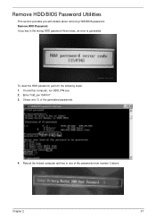
Remove HDD/BIOS Password Utilities This section provides you with details about removing HDD/BIOS password: Remove HDD Password: If you key in one (1) or the generated passwords. 4. On another computer, run HDD_PW.exe. 2. Chose one of the passwords from number 3 above. Reboot the locked computer and key in the wrong HDD password three times, an error is generated. To reset the HDD password, perform the following steps: 1. Enter "hdd_pw 15494 0" 3. Chapter 2 37
Remove HDD/BIOS Password Utilities This section provides you with details about removing HDD/BIOS password: Remove HDD Password: If you key in one (1) or the generated passwords. 4. On another computer, run HDD_PW.exe. 2. Chose one of the passwords from number 3 above. Reboot the locked computer and key in the wrong HDD password three times, an error is generated. To reset the HDD password, perform the following steps: 1. Enter "hdd_pw 15494 0" 3. Chapter 2 37

Service Guide
Page 48
Removing BIOS Passwords: To clear the User or Supervisor passwords, open the DIMM door and use a metal instrument to clean the desired password shown on the screen. The onscreen message determines whether the function is successful or not. 38 Chapter 2 J1 J2 Cleaning BIOS Passwords To clean the User or Supervisor passwords, perform the following steps: 1. From a DOS prompt, execute clnpwd.exe 2. Press 1 or 2 to short the J1 and J2 points.
Removing BIOS Passwords: To clear the User or Supervisor passwords, open the DIMM door and use a metal instrument to clean the desired password shown on the screen. The onscreen message determines whether the function is successful or not. 38 Chapter 2 J1 J2 Cleaning BIOS Passwords To clean the User or Supervisor passwords, perform the following steps: 1. From a DOS prompt, execute clnpwd.exe 2. Press 1 or 2 to short the J1 and J2 points.

Service Guide
Page 49
For example, enter BS2 to change the boot sequence to display the usage screen. 3. Enter into DOS. 2. Execute BS.exe to HDD | CD ROM | LAN | Floppy. Chapter 2 39 Using Boot Sequence Selector The Boot Sequence Selector allows the boot order to be changed without accessing the BIOS. To use Boot Sequence Selector, perform the following steps: 1. Select the desired boot sequence by entering the corresponding sequence.
For example, enter BS2 to change the boot sequence to display the usage screen. 3. Enter into DOS. 2. Execute BS.exe to HDD | CD ROM | LAN | Floppy. Chapter 2 39 Using Boot Sequence Selector The Boot Sequence Selector allows the boot order to be changed without accessing the BIOS. To use Boot Sequence Selector, perform the following steps: 1. Select the desired boot sequence by entering the corresponding sequence.


