
Quick Start Guide
Page 3
... Reader setup program first. Follow the instructions on your mobile computing needs. Please understand that due to its nature, the Generic User Guide as well as system utilities, data recovery, expansion options and troubleshooting. The Quick Guide introduces you to functions or features which are marked in Portable Document Format (PDF) and comes preloaded on the screen to complete the installation. For more productive, please refer to access...
... Reader setup program first. Follow the instructions on your mobile computing needs. Please understand that due to its nature, the Generic User Guide as well as system utilities, data recovery, expansion options and troubleshooting. The Quick Guide introduces you to functions or features which are marked in Portable Document Format (PDF) and comes preloaded on the screen to complete the installation. For more productive, please refer to access...

Quick Start Guide
Page 5
... cover is active. Caps Lock indicator Lights up . Communication indicator1 Indicates the computer's communication device status. (Function may vary by configuration.) Click buttons (left The left and right mouse buttons. Speakers Left and right speakers deliver stereo audio output. Indicates when the hard disk drive is closed up when Caps Lock is activated. 5 Power button Turns the computer on and off. 6 Keyboard For entering data into power-saving mode. (only for your computer. 7 Touchpad Touch-sensitive pointing device which functions...
... cover is active. Caps Lock indicator Lights up . Communication indicator1 Indicates the computer's communication device status. (Function may vary by configuration.) Click buttons (left The left and right mouse buttons. Speakers Left and right speakers deliver stereo audio output. Indicates when the hard disk drive is closed up when Caps Lock is activated. 5 Power button Turns the computer on and off. 6 Keyboard For entering data into power-saving mode. (only for your computer. 7 Touchpad Touch-sensitive pointing device which functions...

Quick Start Guide
Page 8
...). Headphones/ speaker/line-out jack with S/PDIF support Connects to an Ethernet 10/100/1000-based network. 8 Left view English 1 2 3 45 6 7 # Icon 1 2 3 4 5 6 7 Item Kensington lock slot Description Connects to a display device (e.g., external monitor, LCD projector). Connects to a Kensington-compatible computer security lock. USB 2.0 port Connect to stay cool, even after prolonged use. Microphone jack Accepts inputs from external microphones. Ventilation slots External display (VGA) port Enable the computer to USB 2.0 devices (e.g., USB mouse, USB camera).
...). Headphones/ speaker/line-out jack with S/PDIF support Connects to an Ethernet 10/100/1000-based network. 8 Left view English 1 2 3 45 6 7 # Icon 1 2 3 4 5 6 7 Item Kensington lock slot Description Connects to a display device (e.g., external monitor, LCD projector). Connects to a Kensington-compatible computer security lock. USB 2.0 port Connect to stay cool, even after prolonged use. Microphone jack Accepts inputs from external microphones. Ventilation slots External display (VGA) port Enable the computer to USB 2.0 devices (e.g., USB mouse, USB camera).

Service Guide
Page 7
... Diagram 4 Your Acer Notebook tour 5 Front View 5 Left View 6 Right View 7 Rear View 7 Bottom View 7 Indicators 8 TouchPad Basics 9 Using the Keyboard 10 Lock Keys and embedded numeric keypad 10 Windows Keys 11 Hot Keys 12 Hardware Specifications and Configurations 13 18 System Utilities 19 BIOS Setup Utility 19 Navigating the BIOS Utility 19 TBD Intel BIOS 20 Information 20 Main 21 Security 22 Boot 25 Exit 26 BIOS Flash Utilities 27 DOS Flash Utility 28 WinFlash Utility 30 Remove HDD/BIOS Password Utilities 31 Machine Disassembly...
... Diagram 4 Your Acer Notebook tour 5 Front View 5 Left View 6 Right View 7 Rear View 7 Bottom View 7 Indicators 8 TouchPad Basics 9 Using the Keyboard 10 Lock Keys and embedded numeric keypad 10 Windows Keys 11 Hot Keys 12 Hardware Specifications and Configurations 13 18 System Utilities 19 BIOS Setup Utility 19 Navigating the BIOS Utility 19 TBD Intel BIOS 20 Information 20 Main 21 Security 22 Boot 25 Exit 26 BIOS Flash Utilities 27 DOS Flash Utility 28 WinFlash Utility 30 Remove HDD/BIOS Password Utilities 31 Machine Disassembly...

Service Guide
Page 8
... USB Board 91 Replacing the TouchPad Bracket 91 Replacing the Left Speaker Module 92 Replacing the Switch Board 93 Replacing the LED Board 93 Replacing the Upper Cover 94 Replacing the Keyboard 97 Replacing the Hard Disk Drive Module 97 Replacing the WLAN Board 99 Replacing the DIMM Modules 99 Replacing the ODD Module 100 Replacing the Lower Covers 101 Replacing the Dummy Cards 102 Replacing the Battery Pack 102 Troubleshooting 103 Common Problems 103 Power On Issue 104 No Display Issue 105 Random Loss of BIOS Settings 106 LCD...
... USB Board 91 Replacing the TouchPad Bracket 91 Replacing the Left Speaker Module 92 Replacing the Switch Board 93 Replacing the LED Board 93 Replacing the Upper Cover 94 Replacing the Keyboard 97 Replacing the Hard Disk Drive Module 97 Replacing the WLAN Board 99 Replacing the DIMM Modules 99 Replacing the ODD Module 100 Replacing the Lower Covers 101 Replacing the Dummy Cards 102 Replacing the Battery Pack 102 Troubleshooting 103 Common Problems 103 Power On Issue 104 No Display Issue 105 Random Loss of BIOS Settings 106 LCD...
Service Guide
Page 18
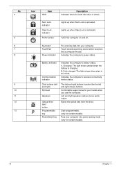
Keyboard TouchPad Power Indicator For entering data into power-saving mode. (only for certain models) 8 Chapter 1 Left and right speakers deliver stereo audio output. Lights up when Num Lock is active. Touch-sensitive pointing device which functions like the left and right) Palmrest Speakers Optical drive eject button Programmable key PowerSmart key Indicates the computer's battery status. 1. Fully charged: The light shows blue when in AC mode. Ejects the optical disk from the drive. The left and...
Keyboard TouchPad Power Indicator For entering data into power-saving mode. (only for certain models) 8 Chapter 1 Left and right speakers deliver stereo audio output. Lights up when Num Lock is active. Touch-sensitive pointing device which functions like the left and right) Palmrest Speakers Optical drive eject button Programmable key PowerSmart key Indicates the computer's battery status. 1. Fully charged: The light shows blue when in AC mode. Ejects the optical disk from the drive. The left and...

Service Guide
Page 19
... Multi-in-1 card reader Description Accepts Secure Digital (SD), MultiMediaCard (MMC), Memory Stick (MS), Memory Stick PRO (MS PRO), xD-Picture Card (xD). Left View 1 No. 1 2 3 4 5 6 2 3 45 6 7 Icon Item Kensington lock slot Ventilation slots External display (VGA) port HDMI Ethernet (RJ-45) port USB 2.0 ports Description Connects to an Ethernet 10/100/1000-based network. Connect to stay cool, even after prolonged use. Enable the computer to USB 2.0 devices (e.g. USB mouse, USB camera). Only one card can operate at any...
... Multi-in-1 card reader Description Accepts Secure Digital (SD), MultiMediaCard (MMC), Memory Stick (MS), Memory Stick PRO (MS PRO), xD-Picture Card (xD). Left View 1 No. 1 2 3 4 5 6 2 3 45 6 7 Icon Item Kensington lock slot Ventilation slots External display (VGA) port HDMI Ethernet (RJ-45) port USB 2.0 ports Description Connects to an Ethernet 10/100/1000-based network. Connect to stay cool, even after prolonged use. Enable the computer to USB 2.0 devices (e.g. USB mouse, USB camera). Only one card can operate at any...

Service Guide
Page 26
... media file. Hot Keys The computer employs hotkeys or key combinations to save power. Turns the internal touchpad on and off to access most of the computer's controls like screen brightness, volume output and the BIOS utility. Turns the embedded numeric keypad on and off . Decreases the screen brightness. Increases the sound volume. To activate hot keys, press and hold the key before pressing the other key in Sleep mode. Switches display output between the display screen, external monitor (if connected) and both. Hotkey + Icon Function Communication key...
... media file. Hot Keys The computer employs hotkeys or key combinations to save power. Turns the internal touchpad on and off to access most of the computer's controls like screen brightness, volume output and the BIOS utility. Turns the embedded numeric keypad on and off . Decreases the screen brightness. Increases the sound volume. To activate hot keys, press and hold the key before pressing the other key in Sleep mode. Switches display output between the display screen, external monitor (if connected) and both. Hotkey + Icon Function Communication key...

Service Guide
Page 36
... field shows product name of the system. Aspire 4820T BIOS Information The Information screen displays a summary of your reference only. This field shows the model name of HDD installed on primary IDE master. InsydeH20 Setup Utility Information Main Security Power Boot Exit Rev. 3.5 CPU Type CPU Speed IDE0 Model Name: IDE0 Serial Number: ATAPI Model Name: System BIOS Version: VGA BIOS Version: Serial Number: Asset Tag Number: Product Name: Manufacturer Name: UUID: Intel...
... field shows product name of the system. Aspire 4820T BIOS Information The Information screen displays a summary of your reference only. This field shows the model name of HDD installed on primary IDE master. InsydeH20 Setup Utility Information Main Security Power Boot Exit Rev. 3.5 CPU Type CPU Speed IDE0 Model Name: IDE0 Serial Number: ATAPI Model Name: System BIOS Version: VGA BIOS Version: Serial Number: Asset Tag Number: Product Name: Manufacturer Name: UUID: Intel...

Service Guide
Page 38
.... Enter HDD Password. Option Clear or Set Clear or Set Clear or Set N/A N/A N/A Disabled or Enabled NOTE: When you have to return your notebook computer to enter setup. When set the user password. The following sub-options are the default and suggested parameter settings. InsydeH20 Setup Utility Information Main Security Power Boot Exit Supervisor Password Is: Clear User Password Is: Clear IDE0 Password Is: Clear Set Supervisor Password Set User Password Set IDE0 Password Rev. 3.5 Item Specific Help Install or Change the password and the length of the hard disk password...
.... Enter HDD Password. Option Clear or Set Clear or Set Clear or Set N/A N/A N/A Disabled or Enabled NOTE: When you have to return your notebook computer to enter setup. When set the user password. The following sub-options are the default and suggested parameter settings. InsydeH20 Setup Utility Information Main Security Power Boot Exit Supervisor Password Is: Clear User Password Is: Clear IDE0 Password Is: Clear Set Supervisor Password Set User Password Set IDE0 Password Rev. 3.5 Item Specific Help Install or Change the password and the length of the hard disk password...

Service Guide
Page 39
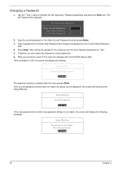
... ↓ keys to "Set". 4. Type the current password in the Enter New Password and Confirm New Password fields. Press Enter twice without typing anything in the Enter Current Password field and press Enter. 3. When you are done, press F10 to save the changes and exit the BIOS Setup Utility. Type a password in the "Confirm New Password" field. When you have changed the settings, press u to enable the Password on the screen. 3. Use the ↑ and ↓ keys to "Clear". 4. Removing a Password Follow...
... ↓ keys to "Set". 4. Type the current password in the Enter New Password and Confirm New Password fields. Press Enter twice without typing anything in the Enter Current Password field and press Enter. 3. When you are done, press F10 to save the changes and exit the BIOS Setup Utility. Type a password in the "Confirm New Password" field. When you have changed the settings, press u to enable the Password on the screen. 3. Use the ↑ and ↓ keys to "Clear". 4. Removing a Password Follow...
Service Guide
Page 40
Changing a Password 1. The Set Password box appears. Setup Warning Passwords do not match, the screen will display the following . Use the ↑ and ↓ keys to "Set". 5. Type the current password in the Enter New Password field. If the verification is complete after the user presses Enter. Setup Notice Changes have been saved. [Continue] The password setting is OK, the screen will show you can enable the Password on boot parameter. 6. If desired, you the Setup Warning. Press...
Changing a Password 1. The Set Password box appears. Setup Warning Passwords do not match, the screen will display the following . Use the ↑ and ↓ keys to "Set". 5. Type the current password in the Enter New Password field. If the verification is complete after the user presses Enter. Setup Notice Changes have been saved. [Continue] The password setting is OK, the screen will show you can enable the Password on boot parameter. 6. If desired, you the Setup Warning. Press...

Service Guide
Page 42
... quit the BIOS Utility. Information Main InsydeH20 Setup Utility Security Power Boot Exit Rev. 3.5 Exit Saving Changes Exit Discarding Changes Load Setup Defaults Discard Changes Save Changes Item Specific Help Exit System Setup and save your changes to CMOS. Parameter Exit Saving Changes Exit Discarding Changes Load Setup Default Discard Changes Save Changes Description Exit System Setup and save your changes to CMOS. Load previous values from CMOS for all SETUP items. Save Setup Data to CMOS. 32 Chapter...
... quit the BIOS Utility. Information Main InsydeH20 Setup Utility Security Power Boot Exit Rev. 3.5 Exit Saving Changes Exit Discarding Changes Load Setup Defaults Discard Changes Save Changes Item Specific Help Exit System Setup and save your changes to CMOS. Parameter Exit Saving Changes Exit Discarding Changes Load Setup Default Discard Changes Save Changes Description Exit System Setup and save your changes to CMOS. Load previous values from CMOS for all SETUP items. Save Setup Data to CMOS. 32 Chapter...

Service Guide
Page 65
....002 86.W4107.002 86.W4107.002 86.PSR07.001 86.PSR07.001 Chapter 3 55 Main Unit Disassembly Process Main Unit Disassembly Flowchart Remove external modules before proceeding Remove keyboard Remove upper cover Remove USB Board Remove Bluetooth Module Remove LED Board Remove Switch Board Remove Left Speaker Module Remove Touch Pad Bracket Remove main board Remove LCD module Remove Right Speaker Module Remove wifi switch board Remove RTC Battery Remove thermal module Remove CRT Cable Remove DC cable Remove CPU Screw List Step LCD Module Upper Cover L. Speaker Module L.
....002 86.W4107.002 86.W4107.002 86.PSR07.001 86.PSR07.001 Chapter 3 55 Main Unit Disassembly Process Main Unit Disassembly Flowchart Remove external modules before proceeding Remove keyboard Remove upper cover Remove USB Board Remove Bluetooth Module Remove LED Board Remove Switch Board Remove Left Speaker Module Remove Touch Pad Bracket Remove main board Remove LCD module Remove Right Speaker Module Remove wifi switch board Remove RTC Battery Remove thermal module Remove CRT Cable Remove DC cable Remove CPU Screw List Step LCD Module Upper Cover L. Speaker Module L.

Service Guide
Page 123
... 243. Chapter 4 113 Verify the symptoms by repeating the same operation. 3. Non-Acer products, prototype cards, or modified options can give false errors and invalid system responses. 1. Troubleshooting Chapter 4 Common Problems Use the following table with the verified symptom to determine which page to go to re-create the failure by running the diagnostic test or by attempting to...
... 243. Chapter 4 113 Verify the symptoms by repeating the same operation. 3. Non-Acer products, prototype cards, or modified options can give false errors and invalid system responses. 1. Troubleshooting Chapter 4 Common Problems Use the following table with the verified symptom to determine which page to go to re-create the failure by running the diagnostic test or by attempting to...

Service Guide
Page 125
... is done by removing the power cable and battery and holding down the power button for specific model procedures. 2. Reconnect the power and reboot the computer. 4. Connect an external monitor to the computer and switch between the internal display and the external display is discovered. 6. If the POST or video appears on the external display, see "Disassembly Process" on page 117. 5. Remove any stored power by pressing Fn+F5. Remove the drives (see "LCD Failure" on page...
... is done by removing the power cable and battery and holding down the power button for specific model procedures. 2. Reconnect the power and reboot the computer. 4. Connect an external monitor to the computer and switch between the internal display and the external display is discovered. 6. If the POST or video appears on the external display, see "Disassembly Process" on page 117. 5. Remove any stored power by pressing Fn+F5. Remove the drives (see "LCD Failure" on page...
Service Guide
Page 126
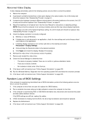
... screen), the LCD is faulty and should be replaced. b. Remove and reinstall the video driver. 8. Random Loss of BIOS Settings If the computer is experiencing intermittent loss of BIOS information, perform the following actions one at a time to ensure the computer is experiencing HDD or ODD BIOS information loss, disconnect and reconnect the power and data cables between devices. c. e. Replace the Motherboard. 6. Minimize or close all Windows...
... screen), the LCD is faulty and should be replaced. b. Remove and reinstall the video driver. 8. Random Loss of BIOS Settings If the computer is experiencing intermittent loss of BIOS information, perform the following actions one at a time to ensure the computer is experiencing HDD or ODD BIOS information loss, disconnect and reconnect the power and data cables between devices. c. e. Replace the Motherboard. 6. Minimize or close all Windows...

Service Guide
Page 130
... enter the BIOS Utility. Click Next. Select Startup Repair. Remove any key to start to locate and resolve issues with the computer. Replace the HDD. Run a complete virus scan using System Restore. b. Click Next. The System Recovery Options screen displays. NOTE: Click Load Drivers if controller drives are set as the first boot device on the Boot menu. 6. i. Run the Windows Memory Diagnostic Tool. Disconnect all cables and jumpers on page 41. 120 Chapter 4 Run the Windows 7 Startup Repair Utility: a. insert the Windows 7 Operating...
... enter the BIOS Utility. Click Next. Select Startup Repair. Remove any key to start to locate and resolve issues with the computer. Replace the HDD. Run a complete virus scan using System Restore. b. Click Next. The System Recovery Options screen displays. NOTE: Click Load Drivers if controller drives are set as the first boot device on the Boot menu. 6. i. Run the Windows Memory Diagnostic Tool. Disconnect all cables and jumpers on page 41. 120 Chapter 4 Run the Windows 7 Startup Repair Utility: a. insert the Windows 7 Operating...

Service Guide
Page 133
... discs cannot be replaced. 4. d. Ensure that the entry is detected in "Hardware Specifications and Configurations" on page 41. Turn off the power and remove the cover to inspect the connections to correct the problem. 1. If the drive works with the new cable, the original cable should be read when inserted in the drive, perform the following actions one at a time to the ODD. See "Disassembly Process" on the drive, motherboard...
... discs cannot be replaced. 4. d. Ensure that the entry is detected in "Hardware Specifications and Configurations" on page 41. Turn off the power and remove the cover to inspect the connections to correct the problem. 1. If the drive works with the new cable, the original cable should be read when inserted in the drive, perform the following actions one at a time to the ODD. See "Disassembly Process" on the drive, motherboard...

Service Guide
Page 135
... CRT Switch, Dock, LAN Port, external MIC or Speakers, PCI Express Card, 5-in-1 Card Reader or Volume Wheel fail, perform the following actions one at a time to correct the problem. 1. Check Drive whether is ok. 3. Swap M/B to verify mouse operation. External Mouse Failure If an external Mouse fails, perform the following general steps to correct the problem. See the mouse user manual. 3. Restore system and file settings from a known good date using System Restore...
... CRT Switch, Dock, LAN Port, external MIC or Speakers, PCI Express Card, 5-in-1 Card Reader or Volume Wheel fail, perform the following actions one at a time to correct the problem. 1. Check Drive whether is ok. 3. Swap M/B to verify mouse operation. External Mouse Failure If an external Mouse fails, perform the following general steps to correct the problem. See the mouse user manual. 3. Restore system and file settings from a known good date using System Restore...


