Service Guide
Page 7
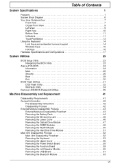
Table of Contents System Specifications 1 Features 1 System Block Diagram 6 Your Acer Notebook tour 7 Front View 7 Closed Front View 9 Left View 9 Right View 10 Bottom View 11 Indicators 11 TouchPad Basics 13 Using the Keyboard 14 Lock ... and embedded numeric keypad 14 Windows Keys 15 Hot Keys 16 Hardware Specifications and Configurations 17 System Utilities 23 BIOS Setup Utility 23 Navigating the BIOS Utility 23 Aspire 4745 BIOS 24 Information 24 Main 25 Security 26 Boot 29 Exit 30 BIOS Flash Utilities 31 DOS Flash Utility 32 WinFlash Utility 34 Remove HDD...
Table of Contents System Specifications 1 Features 1 System Block Diagram 6 Your Acer Notebook tour 7 Front View 7 Closed Front View 9 Left View 9 Right View 10 Bottom View 11 Indicators 11 TouchPad Basics 13 Using the Keyboard 14 Lock ... and embedded numeric keypad 14 Windows Keys 15 Hot Keys 16 Hardware Specifications and Configurations 17 System Utilities 23 BIOS Setup Utility 23 Navigating the BIOS Utility 23 Aspire 4745 BIOS 24 Information 24 Main 25 Security 26 Boot 29 Exit 30 BIOS Flash Utilities 31 DOS Flash Utility 32 WinFlash Utility 34 Remove HDD...

Service Guide
Page 8
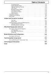
... the Dummy Cards 106 Replacing the Battery Pack 106 Troubleshooting 107 Common Problems 107 Power On Issue 108 No Display Issue 109 Random Loss of BIOS Settings 110 LCD Failure 111 Built-In Keyboard Failure 111 VIII
... the Dummy Cards 106 Replacing the Battery Pack 106 Troubleshooting 107 Common Problems 107 Power On Issue 108 No Display Issue 109 Random Loss of BIOS Settings 110 LCD Failure 111 Built-In Keyboard Failure 111 VIII
Service Guide
Page 9
... 127 Bottom View 128 Clearing Password Check and BIOS Recovery 129 Clearing Password Check 129 BIOS Recovery by Crisis Disk 130 FRU (Field Replaceable Unit) List 131 Acer Aspire 4745 Exploded Diagrams 132 LCD Assembly 132 Acer Aspire 4745 FRU List 135 Screw List 143 Model... Definition and Configuration 144 Acer Aspire 4745 Series 144 Test Compatible Components ...
... 127 Bottom View 128 Clearing Password Check and BIOS Recovery 129 Clearing Password Check 129 BIOS Recovery by Crisis Disk 130 FRU (Field Replaceable Unit) List 131 Acer Aspire 4745 Exploded Diagrams 132 LCD Assembly 132 Acer Aspire 4745 FRU List 135 Screw List 143 Model... Definition and Configuration 144 Acer Aspire 4745 Series 144 Test Compatible Components ...

Service Guide
Page 13
... b/g/n Wi-Fi CERTIFIED™ • Acer InviLink™ 802.11b/g Wi-Fi CERTIFIED™ • Supporting Acer SignalUp™ wireless technology • WPAN: Bluetooth® 2.1+EDR • LAN: Gigabit Ethernet, Wake-on-LAN ready Privacy control • BIOS user, supervisor, HDD passwords • Kensington...; 133 (W) x 59 (D) x 31 (H) mm (5.23 x 2.32 x 1.22 inches) • 390 g (0.86 lbs.)12 with 180 cm DC cable • Acer QuickCharge™ technology13:· • 80% charge in 1 hour· • 2-hour rapid charge system-off • 48.8 W 4400 mAh 6-cell Li-ion standard...
... b/g/n Wi-Fi CERTIFIED™ • Acer InviLink™ 802.11b/g Wi-Fi CERTIFIED™ • Supporting Acer SignalUp™ wireless technology • WPAN: Bluetooth® 2.1+EDR • LAN: Gigabit Ethernet, Wake-on-LAN ready Privacy control • BIOS user, supervisor, HDD passwords • Kensington...; 133 (W) x 59 (D) x 31 (H) mm (5.23 x 2.32 x 1.22 inches) • 390 g (0.86 lbs.)12 with 180 cm DC cable • Acer QuickCharge™ technology13:· • 80% charge in 1 hour· • 2-hour rapid charge system-off • 48.8 W 4400 mAh 6-cell Li-ion standard...
Service Guide
Page 26
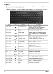
... screen brightness. Increases the sound volume. Increases the screen brightness. Return to access most of the computer's controls like screen brightness, volume output and the BIOS utility. To activate hot keys, press and hold the key before pressing the other key in Sleep mode. Turns the internal touchpad on and off...
... screen brightness. Increases the sound volume. Increases the screen brightness. Return to access most of the computer's controls like screen brightness, volume output and the BIOS utility. To activate hot keys, press and hold the key before pressing the other key in Sleep mode. Turns the internal touchpad on and off...

Service Guide
Page 27
... M 540 M 620 M Cache Size 3 MB 3 MB 3 MB 3 MB 3 MB 4 MB Package PGA988 PGA988 PGA988 PGA988P PGA988 PGA988P Core Voltage 35W 35W 35W 35W 35W 35W Acer P/N KC.33001.DMP KC.35001.DMP KC.43001.DMP KC.52001.DMP KC.54001.DMP KC.62001.DMP CPU Fan True Value Table (Tj = 100... 2500 55 3100 65 3500 75 3900 85 4200 SPL Spec (dBA) 31 34 38 40 • OS Shutdown: 95°C • H/W Shutdown: 100°C BIOS Item BIOS vendor BIOS Version BIOS ROM type Insyde BIOS 1.00 Flash Specification Chapter 1 17
... M 540 M 620 M Cache Size 3 MB 3 MB 3 MB 3 MB 3 MB 4 MB Package PGA988 PGA988 PGA988 PGA988P PGA988 PGA988P Core Voltage 35W 35W 35W 35W 35W 35W Acer P/N KC.33001.DMP KC.35001.DMP KC.43001.DMP KC.52001.DMP KC.54001.DMP KC.62001.DMP CPU Fan True Value Table (Tj = 100... 2500 55 3100 65 3500 75 3900 85 4200 SPL Spec (dBA) 31 34 38 40 • OS Shutdown: 95°C • H/W Shutdown: 100°C BIOS Item BIOS vendor BIOS Version BIOS ROM type Insyde BIOS 1.00 Flash Specification Chapter 1 17

Service Guide
Page 28
... mode • System information Specification 8GB maximum - On above table represents i3 and i5 models. You may combine DIMMs with various capacities to Acer BIOS specification. • DMI utility for a total memory of slot 1 and slot 2 could be reversed. NOTE: The above table, the configuration...memory size per socket Supports DIMM type Supports DIMM Speed Supports DIMM voltage Specification • Flash ROM 4MB • Support ISIPP • Support Acer UI • Support multi-boot • Suspend to RAM (S3)/Disk (S4) • Various hot-keys for system control • Support...
... mode • System information Specification 8GB maximum - On above table represents i3 and i5 models. You may combine DIMMs with various capacities to Acer BIOS specification. • DMI utility for a total memory of slot 1 and slot 2 could be reversed. NOTE: The above table, the configuration...memory size per socket Supports DIMM type Supports DIMM Speed Supports DIMM voltage Specification • Flash ROM 4MB • Support ISIPP • Support Acer UI • Support multi-boot • Suspend to RAM (S3)/Disk (S4) • Various hot-keys for system control • Support...

Service Guide
Page 29
Intel® My WiFi Technology • Easy to 25% over-clocking without requiring BIOS support • Supports Energy Star 5.0 • Small footprint 40-pin QFN (5 x 5 mm) package with Integrated Transceiver • Integrated PHY for Cisco Compatible Extensions* v4 • ...
Intel® My WiFi Technology • Easy to 25% over-clocking without requiring BIOS support • Supports Energy Star 5.0 • Small footprint 40-pin QFN (5 x 5 mm) package with Integrated Transceiver • Integrated PHY for Cisco Compatible Extensions* v4 • ...
Service Guide
Page 33
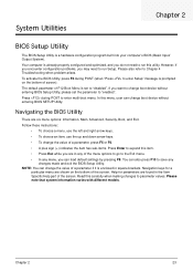
...pressing F9. Chapter 2 23 Your computer is set the parameter to run this menu, user can change boot device without entering BIOS SETUP Utility. Navigating the BIOS Utility There are found in the Item Specific Help part of screen). Help for a particular menu are in any changes made ... Enter to expand this carefully when making changes to save any of a parameter if it is a hardware configuration program built into your computer's BIOS (Basic Input/ Output System). Read this item. • Press Esc while you can also press F10 to parameter values. If you want to...
...pressing F9. Chapter 2 23 Your computer is set the parameter to run this menu, user can change boot device without entering BIOS SETUP Utility. Navigating the BIOS Utility There are found in the Item Specific Help part of screen). Help for a particular menu are in any changes made ... Enter to expand this carefully when making changes to save any of a parameter if it is a hardware configuration program built into your computer's BIOS (Basic Input/ Output System). Read this item. • Press Esc while you can also press F10 to parameter values. If you want to...
Service Guide
Page 34
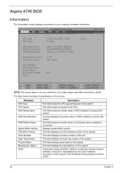
...: VGA BIOS Version: Serial Number: Asset Tag Number: Product Name: Manufacturer Name: UUID: Intel(R) Core(TM) i3 CPU 2.13GHz Hitachi HTS5450116B9A300 091204PBPB06QCK3D3EM TSSTcorp CDDVDW TS-L633C V1.00 Intel V1914 Acer M 330 F1 Help ESC Exit Select Item F5/F6 Change Values F9 Setup Default Select Menu Enter Select SubMenu F10 ... in the system. This field shows the model name of HDD installed on primary IDE master. This field shows the model name of the system. Aspire 4745 BIOS Information The Information screen displays a summary of your reference only. Displays system...
...: VGA BIOS Version: Serial Number: Asset Tag Number: Product Name: Manufacturer Name: UUID: Intel(R) Core(TM) i3 CPU 2.13GHz Hitachi HTS5450116B9A300 091204PBPB06QCK3D3EM TSSTcorp CDDVDW TS-L633C V1.00 Intel V1914 Acer M 330 F1 Help ESC Exit Select Item F5/F6 Change Values F9 Setup Default Select Menu Enter Select SubMenu F10 ... in the system. This field shows the model name of HDD installed on primary IDE master. This field shows the model name of the system. Aspire 4745 BIOS Information The Information screen displays a summary of your reference only. Displays system...
Service Guide
Page 36
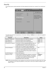
... Change Values F9 Setup Default Select Menu Enter Select SubMenu F10 Save and Exit The table below describes the parameters in this password protects the BIOS Setup Utility from unauthorized use. Enter HDD Password. Press Enter to reset it. 26 Chapter 2 When user password is required or not while... the events defined in this password protects the BIOS Setup Utility from unauthorized access. The user can not either enter the Setup menu nor change the value of the user password. If you ...
... Change Values F9 Setup Default Select Menu Enter Select SubMenu F10 Save and Exit The table below describes the parameters in this password protects the BIOS Setup Utility from unauthorized use. Enter HDD Password. Press Enter to reset it. 26 Chapter 2 When user password is required or not while... the events defined in this password protects the BIOS Setup Utility from unauthorized access. The user can not either enter the Setup menu nor change the value of the user password. If you ...
Service Guide
Page 37
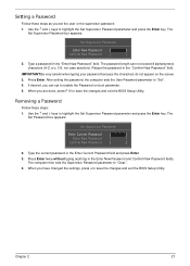
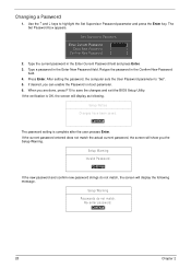
.... 3. Press Enter. Removing a Password Follow these steps as you have changed the settings, press u to save the changes and exit the BIOS Setup Utility. Use the ↑ and ↓ keys to highlight the Set Supervisor Password parameter and press the Enter key. Type the current...desired, you are done, press F10 to enable the Password on the screen. 3. The password length can opt to save the changes and exit the BIOS Setup Utility. After setting the password, the computer sets the User Password parameter to "Clear". 4. When you can not exceed 8 alphanumeric characters (A-Z,...
.... 3. Press Enter. Removing a Password Follow these steps as you have changed the settings, press u to save the changes and exit the BIOS Setup Utility. Use the ↑ and ↓ keys to highlight the Set Supervisor Password parameter and press the Enter key. Type the current...desired, you are done, press F10 to enable the Password on the screen. 3. The password length can opt to save the changes and exit the BIOS Setup Utility. After setting the password, the computer sets the User Password parameter to "Clear". 4. When you can not exceed 8 alphanumeric characters (A-Z,...
Service Guide
Page 38
... Supervisor Password Enter Current Password [ ] Enter New Password [ ] Confirm New Password [ ] 2. If desired, you are done, press F10 to save the changes and exit the BIOS Setup Utility. If the verification is complete after the user presses Enter. Setup Notice Changes have been saved. [Continue] The password setting is OK, the...
... Supervisor Password Enter Current Password [ ] Enter New Password [ ] Confirm New Password [ ] 2. If desired, you are done, press F10 to save the changes and exit the BIOS Setup Utility. If the verification is complete after the user presses Enter. Setup Notice Changes have been saved. [Continue] The password setting is OK, the...
Service Guide
Page 40
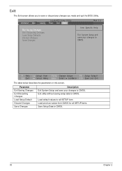
Exit The Exit screen allows you made and quit the BIOS Utility. Information Main InsydeH20 Setup Utility Security Power Boot Exit Rev. 3.5 Exit Saving Changes Exit Discarding Changes Load Setup Defaults Discard Changes Save Changes Item ...
Exit The Exit screen allows you made and quit the BIOS Utility. Information Main InsydeH20 Setup Utility Security Power Boot Exit Rev. 3.5 Exit Saving Changes Exit Discarding Changes Load Setup Defaults Discard Changes Save Changes Item ...
Service Guide
Page 41
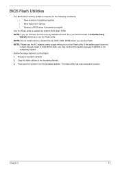
... run the Flash. 1. Chapter 2 31 NOTE: Please use the AC adaptor power supply when you use the Flash utility. Fellow the steps below to finish BIOS flash, you use the Flash. The flash utility has auto-execution function. Prepare a bootable diskette. 2. NOTE: If you do not have a crisis recovery diskette ...at hand, then you should create a Crisis Recovery Diskette before you may not boot the system because the BIOS is required for the following conditions: • New versions of system programs • New features or options • Restore...
... run the Flash. 1. Chapter 2 31 NOTE: Please use the AC adaptor power supply when you use the Flash utility. Fellow the steps below to finish BIOS flash, you use the Flash. The flash utility has auto-execution function. Prepare a bootable diskette. 2. NOTE: If you do not have a crisis recovery diskette ...at hand, then you should create a Crisis Recovery Diskette before you may not boot the system because the BIOS is required for the following conditions: • New versions of system programs • New features or options • Restore...

Service Guide
Page 42
... F1 Help ESC Exit Select Item F5/F6 Change Values F9 Setup Default Select Menu Enter Select SubMenu F10 Save and Exit 3. Press to update BIOS. IDE1 : HL-DT-STDVDRAM GT30N Use < > or < > to select a device, then press to move it up the list. Press F2 during boot to move USB... use the DOS Flash Utility: 1. USB CD/DVDROM : 6. Select Boot Menu to modify the boot priority order, for example, if using USB HDD to Update BIOS, move it down the list, or to enter the Setup Menu. 2. USB FDD : 3. InsydeH20 Setup Utility Information Main Security Boot Exit Boot priority order: Rev...
... F1 Help ESC Exit Select Item F5/F6 Change Values F9 Setup Default Select Menu Enter Select SubMenu F10 Save and Exit 3. Press to update BIOS. IDE1 : HL-DT-STDVDRAM GT30N Use < > or < > to select a device, then press to move it up the list. Press F2 during boot to move USB... use the DOS Flash Utility: 1. USB CD/DVDROM : 6. Select Boot Menu to modify the boot priority order, for example, if using USB HDD to Update BIOS, move it down the list, or to enter the Setup Menu. 2. USB FDD : 3. InsydeH20 Setup Utility Information Main Security Boot Exit Boot priority order: Rev...

Service Guide
Page 43
4. Flash is not connected, the following message displays. Chapter 2 33 NOTE: If the AC power is complete when the message Flash programming complete displays. Plug in the AC power to continue. 5. In flash BIOS, the message Please do not remove AC Power Source displays.
4. Flash is not connected, the following message displays. Chapter 2 33 NOTE: If the AC power is complete when the message Flash programming complete displays. Plug in the AC power to continue. 5. In flash BIOS, the message Please do not remove AC Power Source displays.

Service Guide
Page 45
On another computer, run HDD_PW.exe. 2. Reboot the locked computer and key in the wrong HDD password three times, an error is generated. Chapter 2 35 Remove HDD/BIOS Password Utilities This section provides you with details about removing HDD/BIOS password: Remove HDD Password: If you key in one (1) or the generated passwords. 4. Chose one of the passwords from number 3 above. Enter "hdd_pw 15494 0" 3. To reset the HDD password, perform the following steps: 1.
On another computer, run HDD_PW.exe. 2. Reboot the locked computer and key in the wrong HDD password three times, an error is generated. Chapter 2 35 Remove HDD/BIOS Password Utilities This section provides you with details about removing HDD/BIOS password: Remove HDD Password: If you key in one (1) or the generated passwords. 4. Chose one of the passwords from number 3 above. Enter "hdd_pw 15494 0" 3. To reset the HDD password, perform the following steps: 1.

Service Guide
Page 46
From a DOS prompt, execute clnpwd.exe 2. The onscreen message determines whether the function is successful or not. 36 Chapter 2 G2 G1 Cleaning BIOS Passwords To clean the User or Supervisor passwords, perform the following steps: 1. Press 1 or 2 to short the G1 and G2 points. Removing BIOS Passwords: To clear the User or Supervisor passwords, open the DIMM door and use a metal instrument to clean the desired password shown on the screen.
From a DOS prompt, execute clnpwd.exe 2. The onscreen message determines whether the function is successful or not. 36 Chapter 2 G2 G1 Cleaning BIOS Passwords To clean the User or Supervisor passwords, perform the following steps: 1. Press 1 or 2 to short the G1 and G2 points. Removing BIOS Passwords: To clear the User or Supervisor passwords, open the DIMM door and use a metal instrument to clean the desired password shown on the screen.

Service Guide
Page 47
Select the desired boot sequence by entering the corresponding sequence. For example, enter BS2 to change the boot sequence to be changed without accessing the BIOS. Chapter 2 37 Enter into DOS. 2. Using Boot Sequence Selector The Boot Sequence Selector allows the boot order to HDD | CD ROM | LAN | Floppy. To use Boot Sequence Selector, perform the following steps: 1. Execute BS.exe to display the usage screen. 3.
Select the desired boot sequence by entering the corresponding sequence. For example, enter BS2 to change the boot sequence to be changed without accessing the BIOS. Chapter 2 37 Enter into DOS. 2. Using Boot Sequence Selector The Boot Sequence Selector allows the boot order to HDD | CD ROM | LAN | Floppy. To use Boot Sequence Selector, perform the following steps: 1. Execute BS.exe to display the usage screen. 3.


