User Manual
Page 13
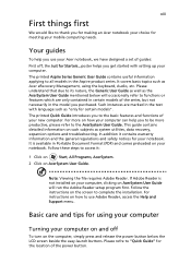
... power button. Your guides To help you get started with language such as the AcerSystem User Guide mentioned below the LCD screen beside the easy-launch buttons. Such instances are only contained in the text with setting up your new computer. If Adobe Reader is available in the Aspire product series. Follow the instructions on AcerSystem User Guide. It covers basic topics such as system utilities, data recovery, expansion options and troubleshooting...
... power button. Your guides To help you get started with language such as the AcerSystem User Guide mentioned below the LCD screen beside the easy-launch buttons. Such instances are only contained in the text with setting up your new computer. If Adobe Reader is available in the Aspire product series. Follow the instructions on AcerSystem User Guide. It covers basic topics such as system utilities, data recovery, expansion options and troubleshooting...
User Manual
Page 62
... to power the computer. If pressing a key does not turn the display back on the icon and deselect the Mute all option. • The volume level may arise during the use the volume control buttons to adjust the volume. Press the display toggle hotkey + to toggle the display back to the computer. • If the Sleep indicator is lit, the computer is in the external USB floppy drive? In Windows, look...
... to power the computer. If pressing a key does not turn the display back on the icon and deselect the Mute all option. • The volume level may arise during the use the volume control buttons to adjust the volume. Press the display toggle hotkey + to toggle the display back to the computer. • If the Sleep indicator is lit, the computer is in the external USB floppy drive? In Windows, look...
Service Guide
Page 8
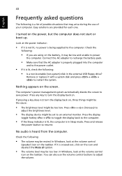
... 56 Removing the Capacitive LED Board 58 Removing the Bluetooth Module 59 Removing the Light Bars 60 Removing the Webcam Module 61 Removing the Power Button 61 Removing the Speaker Mesh Cover Assembly 62 Removing the Touchscreen Control Board 63 Removing the LCD Panel 64 Removing the LCD Panel Brackets 65 Removing the LCD LVDS Cable 65 Removing the System Cables 66 Troubleshooting 67 Hardware Diagnostic Procedure 67 System Check Procedures 67 Checkpoints 68 POST Error Indicators 72 BIOS Recovery 83 Clearing CMOS 84 System Architecture 85 Block Diagram...
... 56 Removing the Capacitive LED Board 58 Removing the Bluetooth Module 59 Removing the Light Bars 60 Removing the Webcam Module 61 Removing the Power Button 61 Removing the Speaker Mesh Cover Assembly 62 Removing the Touchscreen Control Board 63 Removing the LCD Panel 64 Removing the LCD Panel Brackets 65 Removing the LCD LVDS Cable 65 Removing the System Cables 66 Troubleshooting 67 Hardware Diagnostic Procedure 67 System Check Procedures 67 Checkpoints 68 POST Error Indicators 72 BIOS Recovery 83 Clearing CMOS 84 System Architecture 85 Block Diagram...
Service Guide
Page 14
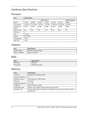
... BIOS Item BIOS chip Setup utility Specification AMI BIOS CMOS Setup Utility Memory Item Controller Number of DIMM slot Maximum memory Data rate Supported capacities DIMM type Supported brands Population rule Specification Integrated in the Intel processor 4 8 GB (using four 2 GB modules) 1333 MT/s 1 or 2 GB 240-pin DDR3 SO-DIMM Apacer, Hynix, Kingston, Nanya, Samsung, and Unifosa You can install memory modules in any combination as long as they match the above specifications. 6 Aspire...
... BIOS Item BIOS chip Setup utility Specification AMI BIOS CMOS Setup Utility Memory Item Controller Number of DIMM slot Maximum memory Data rate Supported capacities DIMM type Supported brands Population rule Specification Integrated in the Intel processor 4 8 GB (using four 2 GB modules) 1333 MT/s 1 or 2 GB 240-pin DDR3 SO-DIMM Apacer, Hynix, Kingston, Nanya, Samsung, and Unifosa You can install memory modules in any combination as long as they match the above specifications. 6 Aspire...
Service Guide
Page 16
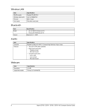
... panel audio jacks - Line-in 5W stereo speakers • Right panel audio jacks - Headphone jack - Microphone jack Webcam Item Resolution Supported models Specification 2.0 MP Primax 50-704A4WNT8 8 Aspire Z3750 / Z3751 / Z5750 / Z5751 AIO Computer Service Guide Wireless LAN Item WLAN module Wireless antenna kit Protocol Form factor Specification Realtek RTL8191SU Lite-On WN6607LH 802.11 b/g/n PCIe Mini Card (half) Bluetooth Item Model Version Specification • Lite-On WB111C Bluetooth Kit • Chicony BC10B Bluetooth Kit Bluetooth 2.1 + EDR Audio Item Controller...
... panel audio jacks - Line-in 5W stereo speakers • Right panel audio jacks - Headphone jack - Microphone jack Webcam Item Resolution Supported models Specification 2.0 MP Primax 50-704A4WNT8 8 Aspire Z3750 / Z3751 / Z5750 / Z5751 AIO Computer Service Guide Wireless LAN Item WLAN module Wireless antenna kit Protocol Form factor Specification Realtek RTL8191SU Lite-On WN6607LH 802.11 b/g/n PCIe Mini Card (half) Bluetooth Item Model Version Specification • Lite-On WB111C Bluetooth Kit • Chicony BC10B Bluetooth Kit Bluetooth 2.1 + EDR Audio Item Controller...
Service Guide
Page 19
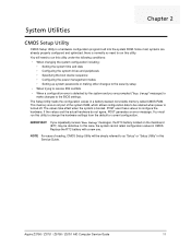
... the boot device sequence • Configuring the power management modes • Setting up system passwords or making other changes to the security setup • When trying to be defective. Since most systems are prompted ("Run Setup" message) to make changes to as "Setup" or "Setup Utility" in this case, the system cannot retain configuration values in a battery-backed nonvolatile memory called CMOS RAM. POST uses these values to change the hardware settings from the default or current configuration...
... the boot device sequence • Configuring the power management modes • Setting up system passwords or making other changes to the security setup • When trying to be defective. Since most systems are prompted ("Run Setup" message) to make changes to as "Setup" or "Setup Utility" in this case, the system cannot retain configuration values in a battery-backed nonvolatile memory called CMOS RAM. POST uses these values to change the hardware settings from the default or current configuration...
Service Guide
Page 24
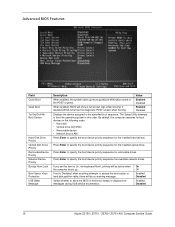
... removable drives. The Setup Utility attempts to boot the operating system in the following order: • Hard disk • Optical drive (CD/DVD) • Removable device • Network boot (LAN) Press Enter to emit error beeps or display error messages during USB device enumeration. If you set to Disabled, when anything attempts to On, the keyboard Num Lock key will show the diagnostic POST screen when booting. Advanced BIOS Features Field Quick Boot Quiet Boot 1st/2nd/3rd/4th Boot Device Hard Disk Drive Priority Optical Disk Drive Priority Removable Device Priority Network...
... removable drives. The Setup Utility attempts to boot the operating system in the following order: • Hard disk • Optical drive (CD/DVD) • Removable device • Network boot (LAN) Press Enter to emit error beeps or display error messages during USB device enumeration. If you set to Disabled, when anything attempts to On, the keyboard Num Lock key will show the diagnostic POST screen when booting. Advanced BIOS Features Field Quick Boot Quiet Boot 1st/2nd/3rd/4th Boot Device Hard Disk Drive Priority Optical Disk Drive Priority Removable Device Priority Network...
Service Guide
Page 30
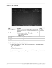
... password. Press Enter to reset it. 22 Aspire Z3750 / Z3751 / Z5750 / Z5751 AIO Computer Service Guide If you forget your password, you may have three tries before you are valid: - Displays the user password status. When set as Installed: • System Date and System Time • Exit Without Saving Press Enter to access and change all settings in the Setup Utility. The following menus will be accessible when this password...
... password. Press Enter to reset it. 22 Aspire Z3750 / Z3751 / Z5750 / Z5751 AIO Computer Service Guide If you forget your password, you may have three tries before you are valid: - Displays the user password status. When set as Installed: • System Date and System Time • Exit Without Saving Press Enter to access and change all settings in the Setup Utility. The following menus will be accessible when this password...
Service Guide
Page 78
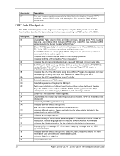
... of PS/2 mouse. Initializes different devices. Displaying sign-on message, CPU information, setup key message, and any platform specific BIOS modules. Checkpoint FF Description The flash has been updated successfully. Do R/W test to F000 ROM at this checkpoint. Detects and initializes the video adapter installed in KBC port. Traps INT1Ch vector to determine if battery power is OK and CMOS checksum is being done on default values and clear passwords. Activate ADM module. The...
... of PS/2 mouse. Initializes different devices. Displaying sign-on message, CPU information, setup key message, and any platform specific BIOS modules. Checkpoint FF Description The flash has been updated successfully. Do R/W test to F000 ROM at this checkpoint. Detects and initializes the video adapter installed in KBC port. Traps INT1Ch vector to determine if battery power is OK and CMOS checksum is being done on default values and clear passwords. Activate ADM module. The...
Service Guide
Page 79
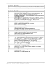
... memory for different BIOS modules. Programming the memory hole or any kind of implementation that needs an adjustment in the system and update the BDA, EBDA...etc. Execute BIOS setup if needed . Late POST initialization of chipset registers. Clean-up work needed . Displays the system configuration screen if enabled. Detect different devices (Parallel ports, serial ports, and coprocessor in NVRam. Log errors encountered during POST. Check boot password if installed. Disables the system configuration display if needed / requested. Aspire...
... memory for different BIOS modules. Programming the memory hole or any kind of implementation that needs an adjustment in the system and update the BDA, EBDA...etc. Execute BIOS setup if needed . Late POST initialization of chipset registers. Clean-up work needed . Displays the system configuration screen if enabled. Detect different devices (Parallel ports, serial ports, and coprocessor in NVRam. Log errors encountered during POST. Check boot password if installed. Disables the system configuration display if needed / requested. Aspire...
Service Guide
Page 80
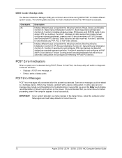
... (Power On Self Text), the Setup utility will switch to correct the error. 72 Aspire Z3750 / Z3751 / Z5750 / Z5751 AIO Computer Service Guide Function 1 initializes all static devices that you press the Enter key to boot successfully. Function 2 searches for and configures PCI input devices and detects if system has standard keyboard controller. Function 5 configures all remaining PnP and PCI devices. Static Device Initialization (function 1); In some cases an error message may indicate a problem with a device configuration. It...
... (Power On Self Text), the Setup utility will switch to correct the error. 72 Aspire Z3750 / Z3751 / Z5750 / Z5751 AIO Computer Service Guide Function 1 initializes all static devices that you press the Enter key to boot successfully. Function 2 searches for and configures PCI input devices and detects if system has standard keyboard controller. Function 5 configures all remaining PnP and PCI devices. Static Device Initialization (function 1); In some cases an error message may indicate a problem with a device configuration. It...
Service Guide
Page 84
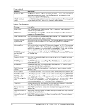
... BIOS POST. A PCI adapter generated an I /O resource conflict when configured by BIOS POST. Usually this case, the BIOS must be displayed if Virus Detection is a fatal error, often indication a problem with system hardware. BIOS POST could not find or load the CPU Microcode Update to the device. This may indicate a problem with system hardware. 76 Aspire Z3750 / Z3751 / Z5750 / Z5751 AIO Computer Service Guide This may indicate a problem with system hardware. This is enabled...
... BIOS POST. A PCI adapter generated an I /O resource conflict when configured by BIOS POST. Usually this case, the BIOS must be displayed if Virus Detection is a fatal error, often indication a problem with system hardware. BIOS POST could not find or load the CPU Microcode Update to the device. This may indicate a problem with system hardware. 76 Aspire Z3750 / Z3751 / Z5750 / Z5751 AIO Computer Service Guide This may indicate a problem with system hardware. This is enabled...
Service Guide
Page 85
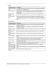
... use default CMOS settings. This error can be replaced. A reset or power cycle is locked. It could also appear when the user intentionally discharges the CMOS battery. Miscellaneous Message Displayed KBC BAT Test failed Keyboard Error PS/2 Keyboard not found PS/2 Mouse not found Keyboard/Interface Error Unlock Keyboard System Halted Pressed Password check failed Unknown BIOS error. Aspire Z3750 / Z3751 / Z5750 / Z5751 AIO Computer Service Guide 77 The password entered does not match the password set in initializing legacy Floppy Controller. CMOS...
... use default CMOS settings. This error can be replaced. A reset or power cycle is locked. It could also appear when the user intentionally discharges the CMOS battery. Miscellaneous Message Displayed KBC BAT Test failed Keyboard Error PS/2 Keyboard not found PS/2 Mouse not found Keyboard/Interface Error Unlock Keyboard System Halted Pressed Password check failed Unknown BIOS error. Aspire Z3750 / Z3751 / Z5750 / Z5751 AIO Computer Service Guide 77 The password entered does not match the password set in initializing legacy Floppy Controller. CMOS...
Service Guide
Page 87
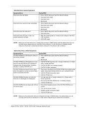
...CMOS Setup and load the default settings. • Hard disk drive cable • Hard disk drive • Mainboard • Enter CMOS Setup and load the default settings. • Hard disk drive • With the system power on • Enter CMOS Setup and load the default settings. output. • Turn up the sound volume. • Speaker power/connection/cable. • CD/DVD-ROM drive. Software displays a reading CD/DVD error. • CD/DVD-ROM may have dirt or foreign material on it . NOTE Make sure the optical disc drive is configured correctly in CMOS Setup and that cable...
...CMOS Setup and load the default settings. • Hard disk drive cable • Hard disk drive • Mainboard • Enter CMOS Setup and load the default settings. • Hard disk drive • With the system power on • Enter CMOS Setup and load the default settings. output. • Turn up the sound volume. • Speaker power/connection/cable. • CD/DVD-ROM drive. Software displays a reading CD/DVD error. • CD/DVD-ROM may have dirt or foreign material on it . NOTE Make sure the optical disc drive is configured correctly in CMOS Setup and that cable...
Service Guide
Page 88
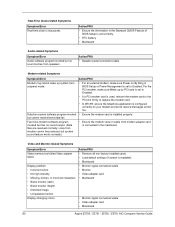
...; Video adapter card • Mainboard • Monitor signal connection/cable • Video adapter card • Mainboard 80 Aspire Z3750 / Z3751 / Z5750 / Z5751 AIO Computer Service Guide For the PCI modem, make sure Wake up system from suspend mode. • For an external modem, make sure Power on By Ring in the Standard CMOS Feature of BIOS Setup is configured correctly for your modem and set to the mainboard Video and Monitor-related Symptoms Symptom/Error Video memory...
...; Video adapter card • Mainboard • Monitor signal connection/cable • Video adapter card • Mainboard 80 Aspire Z3750 / Z3751 / Z5750 / Z5751 AIO Computer Service Guide For the PCI modem, make sure Wake up system from suspend mode. • For an external modem, make sure Power on By Ring in the Standard CMOS Feature of BIOS Setup is configured correctly for your modem and set to the mainboard Video and Monitor-related Symptoms Symptom/Error Video memory...
Service Guide
Page 159
...codes 82 BIOS checkpoints 68 clear CMOS 84 crisis recovery disk 83 recovery 83 specifications 6 system passwords 22 version 14 BIOS Security Features menu 22 block diagram 85 Bluetooth cable, part number 99 module, part number 93 module, remove 59, 60 specifications 8 boot block checkpoints 68 execute 83 boot sequence 16 C capacitive keys board, part number 92 board, remove 58 function cable, part number 98 lens, part number 98 location 3 card reader Index location 4 supported cards 1 chassis, part number 98 checkpoints boot block 68 DIM 72 overview 68 POST 70 CMOS clear 84 CMOS Setup Utility...
...codes 82 BIOS checkpoints 68 clear CMOS 84 crisis recovery disk 83 recovery 83 specifications 6 system passwords 22 version 14 BIOS Security Features menu 22 block diagram 85 Bluetooth cable, part number 99 module, part number 93 module, remove 59, 60 specifications 8 boot block checkpoints 68 execute 83 boot sequence 16 C capacitive keys board, part number 92 board, remove 58 function cable, part number 98 lens, part number 98 location 3 card reader Index location 4 supported cards 1 chassis, part number 98 checkpoints boot block 68 DIM 72 overview 68 POST 70 CMOS clear 84 CMOS Setup Utility...
Service Guide
Page 160
...part number updates 89 G graphics card part number 92 remove 43 H hard disk drive bracket, part number 97 configuration 15 part number 94 power cable, part number 98 remove 45 SATA cable, part number 98 SATA connectors 87 specifications 7 troubleshooting 79 hardware configuration utility 11 exploded view 90 FRU list 89 information display 14 model configurations 105 specifications 6 status monitoring 20 troubleshooting 67 HDD, see hard disk drive 1 HDMI port 4 headphone jack 5 heat sink fan cable connector 87 part number 94 remove 49 HSF, see heat sink fan 49 I I/O cable cover location 4 part...
...part number updates 89 G graphics card part number 92 remove 43 H hard disk drive bracket, part number 97 configuration 15 part number 94 power cable, part number 98 remove 45 SATA cable, part number 98 SATA connectors 87 specifications 7 troubleshooting 79 hardware configuration utility 11 exploded view 90 FRU list 89 information display 14 model configurations 105 specifications 6 status monitoring 20 troubleshooting 67 HDD, see hard disk drive 1 HDMI port 4 headphone jack 5 heat sink fan cable connector 87 part number 94 remove 49 HSF, see heat sink fan 49 I I/O cable cover location 4 part...
Service Guide
Page 161
... 65 light bars cable, part number 98 function cable 98 part number 92 Load Default Settings menu 24 M mainboard component identification 86 part number 92 remove 52 specifications 2 troubleshooting 78 media storage 1 memory check size 14 DIMM slots 87 part number 94 remove 51 specifications 1, 6 troubleshooting 78 microphone 3 microphone jack cable, part number 98 left 4 right 5 model configurations 106 modem board troubleshooting 80 monitor port 4 mouse part number 103 port 4 O ODD bezel remove 34 ODD bracket remove 33 ODD, see optical disc drive 1 online support information 149 operating...
... 65 light bars cable, part number 98 function cable 98 part number 92 Load Default Settings menu 24 M mainboard component identification 86 part number 92 remove 52 specifications 2 troubleshooting 78 media storage 1 memory check size 14 DIMM slots 87 part number 94 remove 51 specifications 1, 6 troubleshooting 78 microphone 3 microphone jack cable, part number 98 left 4 right 5 model configurations 106 modem board troubleshooting 80 monitor port 4 mouse part number 103 port 4 O ODD bezel remove 34 ODD bracket remove 33 ODD, see optical disc drive 1 online support information 149 operating...
Service Guide
Page 162
...11 location 87 RTC clock RTC battery 87 troubleshooting 80 S Save & Exit Setup menu 24 scaler board board, part number 92 cover, part number 97 remove 34 security features 2 side bezel part number 96 remove 54 speakers cable, part number 98 location 3 mesh cover, part number 96 mesh cover, remove 62 part number 95 remove 38 specifications antivirus 2 audio 8 Bluetooth 8 display 8, 9 Ethernet controller 7 hard disk drive 7 memory 6 optical disc drive 7 power supply unit 9 processor 6 system BIOS 6 system chipsets 6 webcam 8 WLAN controller 8 Standard CMOS Features menu 15 supervisor password 22...
...11 location 87 RTC clock RTC battery 87 troubleshooting 80 S Save & Exit Setup menu 24 scaler board board, part number 92 cover, part number 97 remove 34 security features 2 side bezel part number 96 remove 54 speakers cable, part number 98 location 3 mesh cover, part number 96 mesh cover, remove 62 part number 95 remove 38 specifications antivirus 2 audio 8 Bluetooth 8 display 8, 9 Ethernet controller 7 hard disk drive 7 memory 6 optical disc drive 7 power supply unit 9 processor 6 system BIOS 6 system chipsets 6 webcam 8 WLAN controller 8 Standard CMOS Features menu 15 supervisor password 22...
Service Guide
Page 163
... 72 U undetermined problems 82 USB ports bootable device 18 left 4 legacy device 18 right 5 USB/audio board board, part number 92 cable, part number 98 cover, part number 97 remove 36 user password 22 V VGA port 4 VGA to HDMI cable part number 99 volume control keys 3 W wall mount option 5 wall mount plate part number 97 remove 40 webcam cable, part number 99 location 3 module, part number 93 module, remove 61 specifications 8 wireless LAN antennas, part number 93 cable, part number 99 module, part number 93 specifications 8 Aspire Z3750 / Z3751 / Z5750 / Z5751 AIO Computer Service Guide 155
... 72 U undetermined problems 82 USB ports bootable device 18 left 4 legacy device 18 right 5 USB/audio board board, part number 92 cable, part number 98 cover, part number 97 remove 36 user password 22 V VGA port 4 VGA to HDMI cable part number 99 volume control keys 3 W wall mount option 5 wall mount plate part number 97 remove 40 webcam cable, part number 99 location 3 module, part number 93 module, remove 61 specifications 8 wireless LAN antennas, part number 93 cable, part number 99 module, part number 93 specifications 8 Aspire Z3750 / Z3751 / Z5750 / Z5751 AIO Computer Service Guide 155


