Aspire 3000 / 3500 / 5000 Service Guide
Page 7
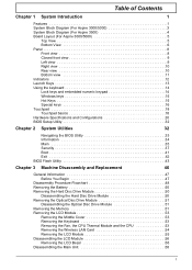
Table of Contents Chapter 1 System Introduction 1 Features 1 System Block Diagram (For Aspire 3000/5000 3 System Block Diagram (For Aspire 3500 4 Board Layout (For Aspire 3000/5000 5 Top View 5 Bottom View 6 Panel 8 Front view 8 Closed front view 9 Left view 9 Right view 10 Rear view 10 Bottom view 11...51 Removing the Memory 51 Removing the LCD Module 53 Removing the Middle Cover 53 Removing the Keyboard 53 Removing the Fan, the CPU Thermal Module and the CPU 53 Removing the Wireless LAN Card 54 Removing the LCD Module 55 Disassembling the LCD Module 56 Removing the LCD ...
Table of Contents Chapter 1 System Introduction 1 Features 1 System Block Diagram (For Aspire 3000/5000 3 System Block Diagram (For Aspire 3500 4 Board Layout (For Aspire 3000/5000 5 Top View 5 Bottom View 6 Panel 8 Front view 8 Closed front view 9 Left view 9 Right view 10 Rear view 10 Bottom view 11...51 Removing the Memory 51 Removing the LCD Module 53 Removing the Middle Cover 53 Removing the Keyboard 53 Removing the Fan, the CPU Thermal Module and the CPU 53 Removing the Wireless LAN Card 54 Removing the LCD Module 55 Disassembling the LCD Module 56 Removing the LCD ...

Aspire 3000 / 3500 / 5000 Service Guide
Page 12
... ALC203 Page 17 BIOS Page 20 AMP MAX9755 Page 18 MIC-In Jack Line-In Jack HP-Out Jack Int. System Block Diagram (For Aspire 3000/5000) 8 7 HOST 200MHz ZCLK 133MHz CLK-GEN AGP 66MHz ICS 952801 PCI 33MHz D USB 48MHz REF 14.318MHz Page 2 3V_ALWAYS 5VPCU... Page 23 1.2V/1.5V 1.8V Page 24 +1.2V_HT +1.5V +1.8V CPU CORE VCC_CORE Page 25 A BATTERY CHARGER Page 26 8 7 6 5 4 3 2 1 DDR SO-DIMM DDR 333 Page 5 CPU AMD Athlon64 SMT uPGA754 Page 3,4 HyperTransport 16x16 1600MT/s Thermal Thermal sensor & Fan NB INTA# SIS M760GX (698 PIN BGA) DVO LVDS Transmitter SIS302ELV Page...
... ALC203 Page 17 BIOS Page 20 AMP MAX9755 Page 18 MIC-In Jack Line-In Jack HP-Out Jack Int. System Block Diagram (For Aspire 3000/5000) 8 7 HOST 200MHz ZCLK 133MHz CLK-GEN AGP 66MHz ICS 952801 PCI 33MHz D USB 48MHz REF 14.318MHz Page 2 3V_ALWAYS 5VPCU... Page 23 1.2V/1.5V 1.8V Page 24 +1.2V_HT +1.5V +1.8V CPU CORE VCC_CORE Page 25 A BATTERY CHARGER Page 26 8 7 6 5 4 3 2 1 DDR SO-DIMM DDR 333 Page 5 CPU AMD Athlon64 SMT uPGA754 Page 3,4 HyperTransport 16x16 1600MT/s Thermal Thermal sensor & Fan NB INTA# SIS M760GX (698 PIN BGA) DVO LVDS Transmitter SIS302ELV Page...

Aspire 3000 / 3500 / 5000 Service Guide
Page 62
... Cover" on page 50. 2. Disconnect the keyboard cable then remove the keyboard. See "Removing the Middle Cover" on page 50. 2. Removing the Keyboard 1. Removing the Fan, the CPU Thermal Module and the CPU 1. Open the notebook as shown. 5. See "Removing the Battery" on page 53. 3. Remove the three screws securing the system...
... Cover" on page 50. 2. Disconnect the keyboard cable then remove the keyboard. See "Removing the Middle Cover" on page 50. 2. Removing the Keyboard 1. Removing the Fan, the CPU Thermal Module and the CPU 1. Open the notebook as shown. 5. See "Removing the Battery" on page 53. 3. Remove the three screws securing the system...

Aspire 3000 / 3500 / 5000 Service Guide
Page 65
... left bracket. Remove the four screws securing the LCD bezel. 9. Take out the LCD assembly from the LCD panel. 12. See "Removing the Fan, the CPU Thermal Module and the CPU" on page 54. 6. See "Removing the Keyboard" on page 55. 7. See "Removing the LCD Module" on page 53. 4. Turn over the LCD...
... left bracket. Remove the four screws securing the LCD bezel. 9. Take out the LCD assembly from the LCD panel. 12. See "Removing the Fan, the CPU Thermal Module and the CPU" on page 54. 6. See "Removing the Keyboard" on page 55. 7. See "Removing the LCD Module" on page 53. 4. Turn over the LCD...


