Aspire 1400 Notebook Service Guide
Page 7
... Diagram 5 Board Layout 6 Top View 6 Bottom View 7 Outlook View 9 Front View 9 Left Panel 11 Right Panel 12 Rear Panel 13 Bottom Panel 14 Indicators 15 Keyboard 17 Lock Keys 17 Embedded Numeric Keypad 18 Windows Keys 19 Hot Keys 20 Keyboard Ergonomics 21 Touchpad 22 Touchpad Basics 22 Launch Keys 24 Hardware Specifications and Configurations 25 Chapter 2 System Utilities 37 BIOS Setup Utility 37 Navigating the BIOS Utility 37 Main 38 Advanced 40 Security 42 Others 45 Boot...
... Diagram 5 Board Layout 6 Top View 6 Bottom View 7 Outlook View 9 Front View 9 Left Panel 11 Right Panel 12 Rear Panel 13 Bottom Panel 14 Indicators 15 Keyboard 17 Lock Keys 17 Embedded Numeric Keypad 18 Windows Keys 19 Hot Keys 20 Keyboard Ergonomics 21 Touchpad 22 Touchpad Basics 22 Launch Keys 24 Hardware Specifications and Configurations 25 Chapter 2 System Utilities 37 BIOS Setup Utility 37 Navigating the BIOS Utility 37 Main 38 Advanced 40 Security 42 Others 45 Boot...
Aspire 1400 Notebook Service Guide
Page 19
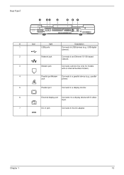
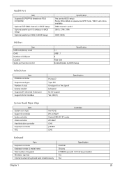
Chapter 1 13 Rear Panel # Icon Item Description 1 USB ports Connects to USB devices (e.g., USB digital camera). 2 Network jack Connects to an Ethernet 10/100-based network. 3 Modem jack Connects a phone line (only for models with an internal fax/data modem). 4 Parallel portModem Connects to a parallel device (e.g., parallel jack printer). 5 Parallel port Connects to a display monitor. 6 External display port Connects t to a display device with S-video input. 7 DC-in jack Connects to the AC adapter.
Chapter 1 13 Rear Panel # Icon Item Description 1 USB ports Connects to USB devices (e.g., USB digital camera). 2 Network jack Connects to an Ethernet 10/100-based network. 3 Modem jack Connects a phone line (only for models with an internal fax/data modem). 4 Parallel portModem Connects to a parallel device (e.g., parallel jack printer). 5 Parallel port Connects to a display monitor. 6 External display port Connects t to a display device with S-video input. 7 DC-in jack Connects to the AC adapter.
Aspire 1400 Notebook Service Guide
Page 23
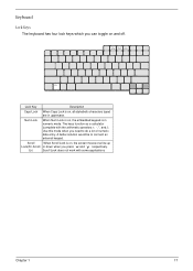
Lk) Scroll Lock does not work with the arithmetic operators +, -, *, and /). The keys function as a calculator (complete with some applications Chapter 1 17 Use this mode when you can toggle on and off. A better solution would be to do a lot of numeric data entry. Scroll .When Scroll Lock is in uppercase. Keyboard Lock Keys The keyboard has four lock keys which you need to connect an external keypad. Num Lock When Num Lock is...
Lk) Scroll Lock does not work with the arithmetic operators +, -, *, and /). The keys function as a calculator (complete with some applications Chapter 1 17 Use this mode when you can toggle on and off. A better solution would be to do a lot of numeric data entry. Scroll .When Scroll Lock is in uppercase. Keyboard Lock Keys The keyboard has four lock keys which you need to connect an external keypad. Num Lock When Num Lock is...
Aspire 1400 Notebook Service Guide
Page 35
... Video) port Supports 32 bit CardBus PCI142 ∅ Type-III/II One type-III or Two type-II Left panel No ZV support Yes (IRQ11) Specification System Board Major Chips Item System core logic Super I/O controller Audio controller Video controller Hard disk drive controller Keyboard controller RTC Intel ICH2 LPC 47N227 Crystal 4299 AC 97 codes ATI M6-P ICH2 pc87591 ICH2 Controller Keyboard Item Keyboard controller Keyboard vendor & model name Total number of USB port Location Serial port function control Specification 1.1 USB 1.1 3 Rear side Enable/Disable by BIOS setup) Note: When Mode...
... Video) port Supports 32 bit CardBus PCI142 ∅ Type-III/II One type-III or Two type-II Left panel No ZV support Yes (IRQ11) Specification System Board Major Chips Item System core logic Super I/O controller Audio controller Video controller Hard disk drive controller Keyboard controller RTC Intel ICH2 LPC 47N227 Crystal 4299 AC 97 codes ATI M6-P ICH2 pc87591 ICH2 Controller Keyboard Item Keyboard controller Keyboard vendor & model name Total number of USB port Location Serial port function control Specification 1.1 USB 1.1 3 Rear side Enable/Disable by BIOS setup) Note: When Mode...
Aspire 1400 Notebook Service Guide
Page 40
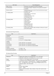
Individual devices such as the CPU and hard disk may be power managed in port, 1 headphone-out with SPDIF port, 1 AC adapter jack (2 pins), 1 type III or type II PCMCIA card bus slots, 3 USB ports (4 pins), 1 RJ-11/RJ-45 port One Housing: Byer FR2000 Panel : Plastic Easy-to-read lock indicators, Status indicators, Power LED, Audio DJ mode indicators Chapter 1 ACPI mode Mech. OS initiated shutdown. All devices in the system are turned off completely. Off (G3) Soft Off...
Individual devices such as the CPU and hard disk may be power managed in port, 1 headphone-out with SPDIF port, 1 AC adapter jack (2 pins), 1 type III or type II PCMCIA card bus slots, 3 USB ports (4 pins), 1 RJ-11/RJ-45 port One Housing: Byer FR2000 Panel : Plastic Easy-to-read lock indicators, Status indicators, Power LED, Audio DJ mode indicators Chapter 1 ACPI mode Mech. OS initiated shutdown. All devices in the system are turned off completely. Off (G3) Soft Off...
Aspire 1400 Notebook Service Guide
Page 49
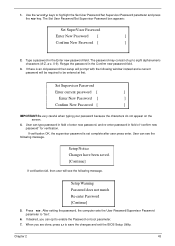
... window instead and a current password will see the following message. Type a password in the Confirm new password field. 3. Press e. User can opt to save the changes and exit the BIOS Setup Utility. Setup Warning Password does not match Re-enter Password [Continue] 5. If desired, you are done, press u to enable the Password on the screen. 4. The password may consist of "confirm new password" for verification. The Set User Password/Set Supervisor Password box appears: Set SuperVisor Password Enter New Password [ ] Confirm New Password...
... window instead and a current password will see the following message. Type a password in the Confirm new password field. 3. Press e. User can opt to save the changes and exit the BIOS Setup Utility. Setup Warning Password does not match Re-enter Password [Continue] 5. If desired, you are done, press u to enable the Password on the screen. 4. The password may consist of "confirm new password" for verification. The Set User Password/Set Supervisor Password box appears: Set SuperVisor Password Enter New Password [ ] Confirm New Password...
Aspire 1400 Notebook Service Guide
Page 50
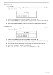
...Chapter 2 Use the w and y keys to save the changes and exit the BIOS Setup Utility. Type a password in the Enter Current Password field and press e. 3. Type the current password in the Enter New Password field. The Set Password box appears: Set Password Enter Current Password [ ] Enter New Password [ ] Confirm New Password [ ] 2. Press e. If desired, you are done, press u to highlight the Set User Password parameter and press the e key. The Set Password box appears: Set Password Enter Current Password [ ] Enter New Password [ ] Confirm New Password [ ] 2. Removing...
...Chapter 2 Use the w and y keys to save the changes and exit the BIOS Setup Utility. Type a password in the Enter Current Password field and press e. 3. Type the current password in the Enter New Password field. The Set Password box appears: Set Password Enter Current Password [ ] Enter New Password [ ] Confirm New Password [ ] 2. Press e. If desired, you are done, press u to highlight the Set User Password parameter and press the e key. The Set Password box appears: Set Password Enter Current Password [ ] Enter New Password [ ] Confirm New Password [ ] 2. Removing...
Aspire 1400 Notebook Service Guide
Page 54
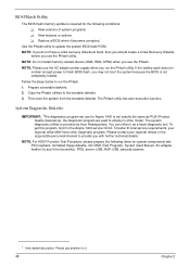
... should create a Crisis Recovery Diskette before you run the Phlash. 1. Please pay attention to it becomes corrupted. BIOS Phlash Utility The BIOS flash memory update is required for system components test: PIO loopback, formatted floppy diskette, CD-DISK (Test Program), Sycard (Card Bus)x2, AC-adapter, feather (to see if the fan works), TPDL server, USB_HUP, USB_barcode scanner. 1 New added description. To better fit local service...
... should create a Crisis Recovery Diskette before you run the Phlash. 1. Please pay attention to it becomes corrupted. BIOS Phlash Utility The BIOS flash memory update is required for system components test: PIO loopback, formatted floppy diskette, CD-DISK (Test Program), Sycard (Card Bus)x2, AC-adapter, feather (to see if the fan works), TPDL server, USB_HUP, USB_barcode scanner. 1 New added description. To better fit local service...
Aspire 1400 Notebook Service Guide
Page 63
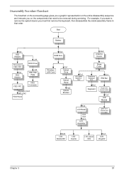
... need to remove the system board, you want to be removed during servicing. Start Battery Ex2 HDD Module Disconnect FDD FPC Ex1 FDD Module Jx4 HDD Drive Jx2 HDD EMI Plate FDD FPC HDD Connector Panasoni: Ex2 MIT: GX2 FDD Panel Ex4 RAM Door Ex2 Antenna Covers Wireless LAN Card Ex1 Optical Drive Optical Panel Ax2 Optical Bracket Ex2 LED power board LS- 1257 Stripe Cover Disconenct Keyboard FFC Ex2 Keyboard Ex1 EMI Bar Disconnect coaxial cable Fx4 LCD Module Ex2 LCD...
... need to remove the system board, you want to be removed during servicing. Start Battery Ex2 HDD Module Disconnect FDD FPC Ex1 FDD Module Jx4 HDD Drive Jx2 HDD EMI Plate FDD FPC HDD Connector Panasoni: Ex2 MIT: GX2 FDD Panel Ex4 RAM Door Ex2 Antenna Covers Wireless LAN Card Ex1 Optical Drive Optical Panel Ax2 Optical Bracket Ex2 LED power board LS- 1257 Stripe Cover Disconenct Keyboard FFC Ex2 Keyboard Ex1 EMI Bar Disconnect coaxial cable Fx4 LCD Module Ex2 LCD...
Aspire 1400 Notebook Service Guide
Page 67
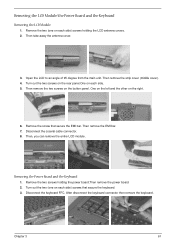
... then remove the keyboard. Chapter 3 61 Remove the two screws holding the LCD antenna covers. 2. Turn out the two (one on each side) screws holding the power board.Then remove the power board. 2. Then remove the strip cover (middle cover). 4. One on the left and the other on the button panel. Removing the LCD Module/the Power Board and the Keyboard Removing the LCD Module 1. Then take away the antenna cover. 3. Disconnect the coaxial cable connector. 8. Then remove...
... then remove the keyboard. Chapter 3 61 Remove the two screws holding the LCD antenna covers. 2. Turn out the two (one on each side) screws holding the power board.Then remove the power board. 2. Then remove the strip cover (middle cover). 4. One on the left and the other on the button panel. Removing the LCD Module/the Power Board and the Keyboard Removing the LCD Module 1. Then take away the antenna cover. 3. Disconnect the coaxial cable connector. 8. Then remove...
Aspire 1400 Notebook Service Guide
Page 78
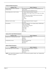
... the charge indicator still does not light up , replace the battery pack. If yes, then replace touch pad PCB. This symptom is connected well, then check if the FFC on touch pad PCB connects properly. 5. From Hardware: 1. If the charge indicator still does not light up , replace the DC/DC charger board. Touchpad Check If the touchpad doesn't work, do the following: From Software: 1. Do not replace a non-defective FRU: 1. After rebooting, run Syn touch driver...
... the charge indicator still does not light up , replace the battery pack. If yes, then replace touch pad PCB. This symptom is connected well, then check if the FFC on touch pad PCB connects properly. 5. From Hardware: 1. If the charge indicator still does not light up , replace the DC/DC charger board. Touchpad Check If the touchpad doesn't work, do the following: From Software: 1. Do not replace a non-defective FRU: 1. After rebooting, run Syn touch driver...
Aspire 1400 Notebook Service Guide
Page 80
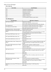
Unlock key switch 0220 Monitor type does not match CMOS - Enter the BIOS Setup Utility and verify the hard disk is dead - Enter the BIOS Setup Utility and verify the parameters (try loading the default settings); Replace the battery and run SETUP 0251 System CMOS checksum bad - then save and restart the computer. Check the system battery. Main board Previous boot-up was not copleted successfully. Enter the BIOS Setup Utility and verify the parameters (try loading the default settings); Replace and run...
Unlock key switch 0220 Monitor type does not match CMOS - Enter the BIOS Setup Utility and verify the hard disk is dead - Enter the BIOS Setup Utility and verify the parameters (try loading the default settings); Replace the battery and run SETUP 0251 System CMOS checksum bad - then save and restart the computer. Check the system battery. Main board Previous boot-up was not copleted successfully. Enter the BIOS Setup Utility and verify the parameters (try loading the default settings); Replace and run...
Aspire 1400 Notebook Service Guide
Page 83
...Hard drive & battery connection board Main board Power source (battery pack and power adapter). Action in Sequence Power source (battery pack and power adapter). Keyboard (if contrast and brightness function key doesn't work LCD is too dark LCD brightness cannot be adjusted LCD contrast cannot be charged Action in Sequence Reconnect the inverter board Inverter board Main board Action in Sequence Enter BIOS Utility to -FRU Error Message LCD-Related Symptoms Symptom / Error LCD backlight doesn't work ). See "Power System Check" on Exit screen, then reboot system. LCD inverter ID LCD cable...
...Hard drive & battery connection board Main board Power source (battery pack and power adapter). Action in Sequence Power source (battery pack and power adapter). Keyboard (if contrast and brightness function key doesn't work LCD is too dark LCD brightness cannot be adjusted LCD contrast cannot be charged Action in Sequence Reconnect the inverter board Inverter board Main board Action in Sequence Enter BIOS Utility to -FRU Error Message LCD-Related Symptoms Symptom / Error LCD backlight doesn't work ). See "Power System Check" on Exit screen, then reboot system. LCD inverter ID LCD cable...
Aspire 1400 Notebook Service Guide
Page 85
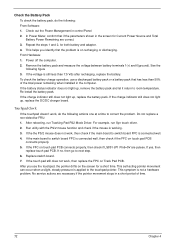
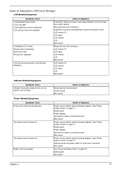
... Setup Utility is set to execute "Load Setup defaults", then reboot system. Power off. Reconnect hard disk/CD-ROM/diskette drives. See "System Diagnostic Diskette" on page 48. Then check if RAM CPU BIOS are well-connected. Printer driver Printer cable Printer Main board Keyboard/Touchpad-Related Symptoms Symptom / Error Keyboard (one or more keys) does not work correctly. Touchpad does not work correctly Print problems. Action in Sequence Reconnect the keyboard cable. Action in Sequence Enter BIOS Setup Utility to Enabled. Keyboard Main board Reconnect touchpad cable...
... Setup Utility is set to execute "Load Setup defaults", then reboot system. Power off. Reconnect hard disk/CD-ROM/diskette drives. See "System Diagnostic Diskette" on page 48. Then check if RAM CPU BIOS are well-connected. Printer driver Printer cable Printer Main board Keyboard/Touchpad-Related Symptoms Symptom / Error Keyboard (one or more keys) does not work correctly. Touchpad does not work correctly Print problems. Action in Sequence Reconnect the keyboard cable. Action in Sequence Enter BIOS Setup Utility to Enabled. Keyboard Main board Reconnect touchpad cable...

Aspire 1400 Notebook Service Guide
Page 86
... advanced diagnostic test for the main board in loop mode at least 10 times. 2. If any error is detected, do the following: 1. Rerun the test to do with a hardware defect, such as: cosmic radiation, electrostatic discharge, or software errors. When analyzing an intermittent problem, do not replace any FRU. 3. Intermittent Problems Intermittent system hang problems can be considered only when...
... advanced diagnostic test for the main board in loop mode at least 10 times. 2. If any error is detected, do the following: 1. Rerun the test to do with a hardware defect, such as: cosmic radiation, electrostatic discharge, or software errors. When analyzing an intermittent problem, do not replace any FRU. 3. Intermittent Problems Intermittent system hang problems can be considered only when...

Aspire 1400 Notebook Service Guide
Page 115
... or TPM, please refer your technical queries to us. Schematics ! Tooling box information ! Debug cards for all your technical queries. and password. Software utilities ! Also contained on : ! Main manuals ! Bios updates ! Spare parts lists ! Service guides for Acer's latest models For these to your local Acer branch office. Repair instructions for all models ! An overview of all the support services we have any suggestions or comments, please do not hesitate...
... or TPM, please refer your technical queries to us. Schematics ! Tooling box information ! Debug cards for all your technical queries. and password. Software utilities ! Also contained on : ! Main manuals ! Bios updates ! Spare parts lists ! Service guides for Acer's latest models For these to your local Acer branch office. Repair instructions for all models ! An overview of all the support services we have any suggestions or comments, please do not hesitate...
Aspire 1400 Notebook Service Guide
Page 117
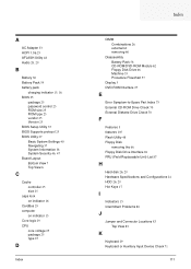
... 26 external 60 removing 60 Disassembly Battery Pack 58 CD-ROM/DVD-ROM Module 62 Floppy Disk Drive 66 Machine 55 Procedure Flowchart 57 Display 5 DVD-ROM Interface 27 E Error Symptom-to-Spare Part Index 73 External CD-ROM Drive Check 70 External Diskette Drive Check 70 F Features 3 features 105 Flash Utility 48 Floppy Disk removing the 66 Floppy Disk Drive Interface 26 FRU (Field Replaceable Unit) List 87 H Hard disk 26, 29 Hardware Specifications and Configurations 24 HDD 26, 29 Hot Keys 17 I Indicators 15 Intermittent Problems...
... 26 external 60 removing 60 Disassembly Battery Pack 58 CD-ROM/DVD-ROM Module 62 Floppy Disk Drive 66 Machine 55 Procedure Flowchart 57 Display 5 DVD-ROM Interface 27 E Error Symptom-to-Spare Part Index 73 External CD-ROM Drive Check 70 External Diskette Drive Check 70 F Features 3 features 105 Flash Utility 48 Floppy Disk removing the 66 Floppy Disk Drive Interface 26 FRU (Field Replaceable Unit) List 87 H Hard disk 26, 29 Hardware Specifications and Configurations 24 HDD 26, 29 Hot Keys 17 I Indicators 15 Intermittent Problems...
Quick Start Guide
Page 9
... needs. For instructions on how your computer can help you use Adobe Reader, access the Help and Support menu. * IMPORTANT NOTICE: Please note that the guides mentioned herein, whether in printed or electronic form, are for errors contained in these guides shall constitute a representation or warranty by Acer with setting up your computer. Acer expressly disclaims any liability for your Acer notebook, we have designed a set...
... needs. For instructions on how your computer can help you use Adobe Reader, access the Help and Support menu. * IMPORTANT NOTICE: Please note that the guides mentioned herein, whether in printed or electronic form, are for errors contained in these guides shall constitute a representation or warranty by Acer with setting up your computer. Acer expressly disclaims any liability for your Acer notebook, we have designed a set...
Quick Start Guide
Page 11
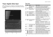
... you use the computer. 12 HDD indicator Indicates when the hard disk drive is activated. Num Lock Lights up when Caps Lock is activated. 1. Quick Guide Your Aspire One tour After setting up your computer as illustrated in AC mode. 8 Communication Indicates the status of 3G/Wireless LAN indicator1 communication. Fully charged: The light shows blue when in the Just for sound recording. 3 Display screen Also called Liquid-Crystal Display (LCD), displays computer output (configuration may vary by model). 4 Power button Turns the...
... you use the computer. 12 HDD indicator Indicates when the hard disk drive is activated. Num Lock Lights up when Caps Lock is activated. 1. Quick Guide Your Aspire One tour After setting up your computer as illustrated in AC mode. 8 Communication Indicates the status of 3G/Wireless LAN indicator1 communication. Fully charged: The light shows blue when in the Just for sound recording. 3 Display screen Also called Liquid-Crystal Display (LCD), displays computer output (configuration may vary by model). 4 Power button Turns the...
Quick Start Guide
Page 13
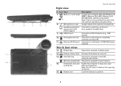
... the computer's main memory. 15 Ventilation slots and Enable the computer to an Ethernet 10/100/1000-based network. Quick Guide Right view # Icon Item Description 7 Multi-in jack Accepts inputs from external microphones. Note: Do not cover or obstruct the opening of the fan. 16 Battery lock Locks the battery in position. 6 Note: Push to audio line-out devices line-out jack with screws). Headphone/speaker/ Connects to remove/install the card.
... the computer's main memory. 15 Ventilation slots and Enable the computer to an Ethernet 10/100/1000-based network. Quick Guide Right view # Icon Item Description 7 Multi-in jack Accepts inputs from external microphones. Note: Do not cover or obstruct the opening of the fan. 16 Battery lock Locks the battery in position. 6 Note: Push to audio line-out devices line-out jack with screws). Headphone/speaker/ Connects to remove/install the card.


