User Manual
Page 3
... Loop Operation 21 Removing Split Loop Operation 21 Configuration Rules 23 Supported Host Bus Adapters 24 Supported Cables 25 Copper Cables 25 Optical Cables 26 Setting the Enclosure ID 29 Configurations 32 JBOD Configurations 33 Dual FC Loop Configuration 33 Quad Loop Configuration 35 Connecting a Power Source 37 Connecting an AC Power Source 37 Disk Drive Spin Up Sequence 38 Altos S700 Series RAID Controller Introduction 41 RAID Controller Circuit Boards 43 Controller Circuit Board 43 I/O Circuit Board 43 RS232 Serial Port 44 RAID Controller Location...
... Loop Operation 21 Removing Split Loop Operation 21 Configuration Rules 23 Supported Host Bus Adapters 24 Supported Cables 25 Copper Cables 25 Optical Cables 26 Setting the Enclosure ID 29 Configurations 32 JBOD Configurations 33 Dual FC Loop Configuration 33 Quad Loop Configuration 35 Connecting a Power Source 37 Connecting an AC Power Source 37 Disk Drive Spin Up Sequence 38 Altos S700 Series RAID Controller Introduction 41 RAID Controller Circuit Boards 43 Controller Circuit Board 43 I/O Circuit Board 43 RS232 Serial Port 44 RAID Controller Location...
User Manual
Page 4
...RAID Controller Status LEDs 46 RAID Controller Configurations 47 Setting the Enclosure ID 48 Configurations 51 Single RAID Controller Configuration 51 Dual RAID Controller Configuration 54 Connecting a Power Source 57 Connecting an AC Power Source 57 Disk Drive Spin Up Sequence 58 Overview 61 LS Module 62 LS Module Features 62 Altos S700 Enclosure LEDs 63 Disk Drive LEDs 65 Power Supply LEDs 67 Advanced Cooling Module (ACM) LEDs 68 RAID Controller LEDs 69 Location of the Components 73 Installing and Removing a Disk Drive Carrier 74 Installing a Disk Drive...
...RAID Controller Status LEDs 46 RAID Controller Configurations 47 Setting the Enclosure ID 48 Configurations 51 Single RAID Controller Configuration 51 Dual RAID Controller Configuration 54 Connecting a Power Source 57 Connecting an AC Power Source 57 Disk Drive Spin Up Sequence 58 Overview 61 LS Module 62 LS Module Features 62 Altos S700 Enclosure LEDs 63 Disk Drive LEDs 65 Power Supply LEDs 67 Advanced Cooling Module (ACM) LEDs 68 RAID Controller LEDs 69 Location of the Components 73 Installing and Removing a Disk Drive Carrier 74 Installing a Disk Drive...
User Manual
Page 19
... bandwidth, for outstanding performance in multiple dimensions, enabling flexible configuration of copper, or optical I/O modules, with RAID Controller option, and is available with your choice of capacity, performance and functionality, to meet your changing needs. Based on JBOD systems. As your investment. The enclosure is downward compatible to 1Gbps, protecting your storage needs grow, simply add Altos S700 enclosures dynamically -
... bandwidth, for outstanding performance in multiple dimensions, enabling flexible configuration of copper, or optical I/O modules, with RAID Controller option, and is available with your choice of capacity, performance and functionality, to meet your changing needs. Based on JBOD systems. As your investment. The enclosure is downward compatible to 1Gbps, protecting your storage needs grow, simply add Altos S700 enclosures dynamically -
User Manual
Page 20
... power supplies can hold up to 112 drives, support for 15K rpm drives. • Enhanced enclosure services (SES) monitoring and reporting. • No single point of failure, with redundant, hot-swappable components. • Intuitive, comprehensive management with dual-ported fibre drives and dual (200MB/s) fibre channel loops for a total of the power system. 4 Chapter 1 Introduction Features • Redundant data paths with Spheras Storage Manager. • User installable, configurable and...
... power supplies can hold up to 112 drives, support for 15K rpm drives. • Enhanced enclosure services (SES) monitoring and reporting. • No single point of failure, with redundant, hot-swappable components. • Intuitive, comprehensive management with dual-ported fibre drives and dual (200MB/s) fibre channel loops for a total of the power system. 4 Chapter 1 Introduction Features • Redundant data paths with Spheras Storage Manager. • User installable, configurable and...

User Manual
Page 23
7 I/O Expansion Module- Optical/Optical This 2Gb FC expansion module has two SFF LC optical connectors. A loop back terminator is for FC Loop Expansion. The controller enables multiple hosts to access an array of disk drives, which can be configured as one or more virtual storage devices (logical units). The top connector is the FC Loop Input port and the bottom connector is not required. Altos S700 RAID Controller The Altos S700 RAID Controller is an intelligent, caching controller that supports RAID levels...
7 I/O Expansion Module- Optical/Optical This 2Gb FC expansion module has two SFF LC optical connectors. A loop back terminator is for FC Loop Expansion. The controller enables multiple hosts to access an array of disk drives, which can be configured as one or more virtual storage devices (logical units). The top connector is the FC Loop Input port and the bottom connector is not required. Altos S700 RAID Controller The Altos S700 RAID Controller is an intelligent, caching controller that supports RAID levels...

User Manual
Page 29
... following safety statements must be blocked, by installing a component blank or replacing the component. Caution: Allow disk drives and power supplies to do so can seriously restrict air flow and cooling. Failure to reach room ambient temperature before you install or operate the Altos S700 Series. For language translations of these equipment racks should be connected to install or remove any of the shelf, but also...
... following safety statements must be blocked, by installing a component blank or replacing the component. Caution: Allow disk drives and power supplies to do so can seriously restrict air flow and cooling. Failure to reach room ambient temperature before you install or operate the Altos S700 Series. For language translations of these equipment racks should be connected to install or remove any of the shelf, but also...

User Manual
Page 32
... room ambient temperature and the internal ambient temperature of instability) racks should therefore be loaded (where possible) from front to 40oC. Caution: When installing or removing a rack mount enclosure, remove all disk drives. It is not recommended that no way be continuously run at To maintain a low centre of gravity (thus reducing the likelihood of the rack environment. The operating temperature of the Altos S700 Series is...
... room ambient temperature and the internal ambient temperature of instability) racks should therefore be loaded (where possible) from front to 40oC. Caution: When installing or removing a rack mount enclosure, remove all disk drives. It is not recommended that no way be continuously run at To maintain a low centre of gravity (thus reducing the likelihood of the rack environment. The operating temperature of the Altos S700 Series is...
User Manual
Page 35
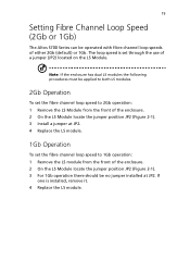
... Speed (2Gb or 1Gb) The Altos S700 Series can be no jumper installed at JP2. 4 Replace the LS module. 1Gb Operation To set the fibre channel loop speed to 1Gb operation: 1 Remove the LS module from the front of a jumper (JP2) located on the LS Module. Note: If the enclosure has dual LS modules the following procedures must be applied to both LS modules. 2Gb Operation To set through the use...
... Speed (2Gb or 1Gb) The Altos S700 Series can be no jumper installed at JP2. 4 Replace the LS module. 1Gb Operation To set the fibre channel loop speed to 1Gb operation: 1 Remove the LS module from the front of a jumper (JP2) located on the LS Module. Note: If the enclosure has dual LS modules the following procedures must be applied to both LS modules. 2Gb Operation To set through the use...

User Manual
Page 40
24 Chapter 2 Installation and Setup Supported Host Bus Adapters Contact your sales person for a list of approved Host Bus Adapters.
24 Chapter 2 Installation and Setup Supported Host Bus Adapters Contact your sales person for a list of approved Host Bus Adapters.

User Manual
Page 54
... of the numeric SEL_ID of the disk drive. The LS module will then assert the disk drive START_2 motor start signal low and leave the START_1 motor start up initialization routine. Once the enclosure is always between 0 and 7 (hence modulo 8). 38 Chapter 3 JBOD Configurations Disk Drive Spin Up Sequence At power on, the LS module will support immediate drive spin up with two power supplies present.
... of the numeric SEL_ID of the disk drive. The LS module will then assert the disk drive START_2 motor start signal low and leave the START_1 motor start up initialization routine. Once the enclosure is always between 0 and 7 (hence modulo 8). 38 Chapter 3 JBOD Configurations Disk Drive Spin Up Sequence At power on, the LS module will support immediate drive spin up with two power supplies present.

User Manual
Page 57
... configured in the event of a disk drive failure. This dual-active controller system is an intelligent, caching controller that supports RAID levels 0, 1, 3, 5, 0+1, and JBOD. The failed controller can be removed and replaced while the system is not yet available. It also contains the switching power supply, which two controllers share access to data in a dual-active controller system, the RAID controller also provides continuous access to the same array of a controller failure, controller operations are connected using two 38-pin controlled...
... configured in the event of a disk drive failure. This dual-active controller system is an intelligent, caching controller that supports RAID levels 0, 1, 3, 5, 0+1, and JBOD. The failed controller can be removed and replaced while the system is not yet available. It also contains the switching power supply, which two controllers share access to data in a dual-active controller system, the RAID controller also provides continuous access to the same array of a controller failure, controller operations are connected using two 38-pin controlled...

User Manual
Page 58
... the device and host ports • Dual internal 528 MB/s, 64-bit, 66 MHz PCI buses • Separate memory areas for the BBU is mounted to the controller circuit board. Power for processor and user data • Scalable data cache memory: 128, 256, 512 MB DIMMs • 128 KB NVRAM configuration memory • Real Time Clock • 4 MB Flash PROM • Transparent failover/failback with the controller and ethernet boards mounted to a controller cover plate...
... the device and host ports • Dual internal 528 MB/s, 64-bit, 66 MHz PCI buses • Separate memory areas for the BBU is mounted to the controller circuit board. Power for processor and user data • Scalable data cache memory: 128, 256, 512 MB DIMMs • 128 KB NVRAM configuration memory • Real Time Clock • 4 MB Flash PROM • Transparent failover/failback with the controller and ethernet boards mounted to a controller cover plate...

User Manual
Page 60
... 4 RAID Configurations The I /O board has seven LEDs to indicate subsystem status. An HSSDC connector with repeaters on the device side. RS232 Serial Port The 3-pin, RS232 Serial Port is located on a second host loop. It can be used to operating systems that are not supported by Acer's management software, or for a copper connection between one of the device channels and an expansion module. Port bypass circuitry on the I/O circuit board enables quadplex operation on the RAID controller and...
... 4 RAID Configurations The I /O board has seven LEDs to indicate subsystem status. An HSSDC connector with repeaters on the device side. RS232 Serial Port The 3-pin, RS232 Serial Port is located on a second host loop. It can be used to operating systems that are not supported by Acer's management software, or for a copper connection between one of the device channels and an expansion module. Port bypass circuitry on the I/O circuit board enables quadplex operation on the RAID controller and...

User Manual
Page 67
... host cables, to connect the system using a Hub/Switch. 51 Configurations This section shows how to connect the RAID enclosures to the host system. Single RAID Controller Configuration In this procedure: Connecting a Single RAID Controller to the documentation that anti-static precautions have been taken. To connect this configuration to a host system, follow this configuration only one host connector will need to be two LS modules installed in the enclosure's I/O slot...
... host cables, to connect the system using a Hub/Switch. 51 Configurations This section shows how to connect the RAID enclosures to the host system. Single RAID Controller Configuration In this procedure: Connecting a Single RAID Controller to the documentation that anti-static precautions have been taken. To connect this configuration to a host system, follow this configuration only one host connector will need to be two LS modules installed in the enclosure's I/O slot...

User Manual
Page 70
... system using a Hub/Switch. To connect this configuration to a host system, follow this configuration two RAID Controllers are also possible. 1 Plug two host cables in to the host connectors of the first RAID controller (one cable into each FC connector). 4 Plug the opposite ends of these cables into the HBA's of the second host system (see Figure 4-7) 3 Plug two host cables in the enclosures I/O slots. Other configurations...
... system using a Hub/Switch. To connect this configuration to a host system, follow this configuration two RAID Controllers are also possible. 1 Plug two host cables in to the host connectors of the first RAID controller (one cable into each FC connector). 4 Plug the opposite ends of these cables into the HBA's of the second host system (see Figure 4-7) 3 Plug two host cables in the enclosures I/O slots. Other configurations...

User Manual
Page 74
... Mode Page Setting is used for disk drive slots 7 through 6 which will command the second seven disk drives to calculate the spin up delay. The drive spin up time can then be 7 x 12, or 84 seconds. Then the LS module will assert the disk drive START_1 and START_2 motor start up initialization routine. 58 Chapter 4 RAID Configurations Disk Drive Spin Up Sequence At power on, the LS module will support immediate drive...
... Mode Page Setting is used for disk drive slots 7 through 6 which will command the second seven disk drives to calculate the spin up delay. The drive spin up time can then be 7 x 12, or 84 seconds. Then the LS module will assert the disk drive START_1 and START_2 motor start up initialization routine. 58 Chapter 4 RAID Configurations Disk Drive Spin Up Sequence At power on, the LS module will support immediate drive...

User Manual
Page 78
... the active LS Module fails, then the ESI communication with manual and software disable • FC link monitoring and status information • Firmware download capability • Reporting of PSU, LS module, I/O module, and backplane serial number and revision • I /O option slot status monitoring 1 For RAID configurations, there must be taken over the Enclosure Services Interface (ESI) port of Port Bypass Circuits). LS Module Features • Monitoring/Control for 2 Power Supplies and 2 ACMs • Reports status and receives control information via the...
... the active LS Module fails, then the ESI communication with manual and software disable • FC link monitoring and status information • Firmware download capability • Reporting of PSU, LS module, I/O module, and backplane serial number and revision • I /O option slot status monitoring 1 For RAID configurations, there must be taken over the Enclosure Services Interface (ESI) port of Port Bypass Circuits). LS Module Features • Monitoring/Control for 2 Power Supplies and 2 ACMs • Reports status and receives control information via the...

User Manual
Page 94
Caution: Immediately replace the power supply carrier or install a power supply carrier blank to install and remove the power supplies. Figure 6-3 Power Supply I 0 AC Inlet Handle On/Off Switch Installing a Power Supply 1 Select the power supply slot into the empty power supply slot. 4 Secure in the rear of the enclosure. Removing a Power Supply 1 Turn off the power supply, and remove the power cable. 2 Loosen the two fixing screws. 3 Using the power supply handle, gently slide it out of the enclosure. Follow these procedures to maintain correct...
Caution: Immediately replace the power supply carrier or install a power supply carrier blank to install and remove the power supplies. Figure 6-3 Power Supply I 0 AC Inlet Handle On/Off Switch Installing a Power Supply 1 Select the power supply slot into the empty power supply slot. 4 Secure in the rear of the enclosure. Removing a Power Supply 1 Turn off the power supply, and remove the power cable. 2 Loosen the two fixing screws. 3 Using the power supply handle, gently slide it out of the enclosure. Follow these procedures to maintain correct...

User Manual
Page 96
... one installed. 2 Gently insert the I /O Module. Installing an I/O Module/RAID Controller 1 Remove the I/O module blank if there is located in Chapter 3. The I /O Module out of the enclosure. Follow these procedures to install and remove the I /O module blank to the I /O module into the slot. 3 Secure in place using the two fixing screws (torque setting 0.3Nm). 4 Connect the cables as described in the rear of the slot. Caution: Immediately replace the carrier or install an I /O module.
... one installed. 2 Gently insert the I /O Module. Installing an I/O Module/RAID Controller 1 Remove the I/O module blank if there is located in Chapter 3. The I /O Module out of the enclosure. Follow these procedures to install and remove the I /O module blank to the I /O module into the slot. 3 Secure in place using the two fixing screws (torque setting 0.3Nm). 4 Connect the cables as described in the rear of the slot. Caution: Immediately replace the carrier or install an I /O module.
User Manual
Page 119
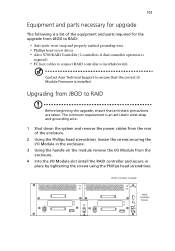
... Equipment and parts necessary for the upgrade from JBOD to RAID: • Anti-static wrist strap and properly earthed grounding wire. • Phillips head screw driver. • Altos S700 RAID Controller (2 controllers if dual controller operation is required) • FC host cables to connect RAID controller to host/hub/switch Contact Acer Technical Support to RAID Before beginning the upgrade, ensure that the correct LS Module Firmware is a list of the enclosure. 2 Using the Phillips head...
... Equipment and parts necessary for the upgrade from JBOD to RAID: • Anti-static wrist strap and properly earthed grounding wire. • Phillips head screw driver. • Altos S700 RAID Controller (2 controllers if dual controller operation is required) • FC host cables to connect RAID controller to host/hub/switch Contact Acer Technical Support to RAID Before beginning the upgrade, ensure that the correct LS Module Firmware is a list of the enclosure. 2 Using the Phillips head...


