
User Manual
Page 3
... Altos S300 component in accordance with Acer Technical Support a Return Material Authorization (RMA) number will be issued for ninety (90) days from the date of shipment. Following receipt of an RMA, the Purchaser is unable to resolve the problem via phone with the schedules listed below. Questionable cables should be returned to Acer, freight prepaid where they will be repaired or replaced by Acer...
... Altos S300 component in accordance with Acer Technical Support a Return Material Authorization (RMA) number will be issued for ninety (90) days from the date of shipment. Following receipt of an RMA, the Purchaser is unable to resolve the problem via phone with the schedules listed below. Questionable cables should be returned to Acer, freight prepaid where they will be repaired or replaced by Acer...

User Manual
Page 7
... openings should never be operated from overheating, these instructions carefully. This product should never be placed near water. 4. Refer all warnings and instructions marked on a bed, sofa, rug, or other risks. Follow all servicing to the product. 5. Do not attempt to service this product from the wall outlet and refer servicing to protect it from the type of power available...
... openings should never be operated from overheating, these instructions carefully. This product should never be placed near water. 4. Refer all warnings and instructions marked on a bed, sofa, rug, or other risks. Follow all servicing to the product. 5. Do not attempt to service this product from the wall outlet and refer servicing to protect it from the type of power available...
User Manual
Page 9
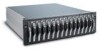
... the Altos S300 series storage array 3 Features 4 Disk drive carrier 5 Power supplies 5 Cooling system 6 I/O modules 7 Enclosure Services Module 7 Terminating Services Module 8 Concentrator Services Module 8 2 Installation precautions 9 ESD precautions 11 Safety precautions 12 Unpacking and initial setup 13 Rack installation precautions 14 Environmental consideration 14 Electrical consideration 14 Mechanical consideration 15 3 Cabling and configuration 17 Altos S300 series SCSI ID assignments 19 I/O module LEDs 20 ESM/CSM LEDs 20 TSM LED 20 Cabling...
... the Altos S300 series storage array 3 Features 4 Disk drive carrier 5 Power supplies 5 Cooling system 6 I/O modules 7 Enclosure Services Module 7 Terminating Services Module 8 Concentrator Services Module 8 2 Installation precautions 9 ESD precautions 11 Safety precautions 12 Unpacking and initial setup 13 Rack installation precautions 14 Environmental consideration 14 Electrical consideration 14 Mechanical consideration 15 3 Cabling and configuration 17 Altos S300 series SCSI ID assignments 19 I/O module LEDs 20 ESM/CSM LEDs 20 TSM LED 20 Cabling...
User Manual
Page 10
... configuration 28 Dual concentrator services modules 28 Join/Split bus jumper 30 Powering on the Altos S300 series enclosure 31 Altos S300 series jumper settings 31 Powering on an AC enclosure 32 4 System monitoring 33 Overview 35 Environmental status (ES) block 36 Features 36 Alarm buzzer mute 38 Enclosure front panel LEDs 39 Disk drive carrier LEDs 40 Power supply LEDs 42 Advanced cooling module (ACM) LEDs 43 5 Installing and removing components 45 Location of the Components 47 Installing...
... configuration 28 Dual concentrator services modules 28 Join/Split bus jumper 30 Powering on the Altos S300 series enclosure 31 Altos S300 series jumper settings 31 Powering on an AC enclosure 32 4 System monitoring 33 Overview 35 Environmental status (ES) block 36 Features 36 Alarm buzzer mute 38 Enclosure front panel LEDs 39 Disk drive carrier LEDs 40 Power supply LEDs 42 Advanced cooling module (ACM) LEDs 43 5 Installing and removing components 45 Location of the Components 47 Installing...

User Manual
Page 14
... Advanced Cooling Modules (ACM) providing n+1 redundancy on fans. • Two rear removable I/O option modules provide active/passive failure redundancy on environmental monitoring, or per Bus Monitoring. • Multi-MODE SCSI Interface Ultra 160. • Hot plug of power supplies and ACM's. • Maximum configurations of drives supported with one or two power supplies. • Failure indication of all Field Replaceable Units (FRU) via LEDs and audible alarm (with alarm mute button). • Disk drive hot plug support. •...
... Advanced Cooling Modules (ACM) providing n+1 redundancy on fans. • Two rear removable I/O option modules provide active/passive failure redundancy on environmental monitoring, or per Bus Monitoring. • Multi-MODE SCSI Interface Ultra 160. • Hot plug of power supplies and ACM's. • Maximum configurations of drives supported with one or two power supplies. • Failure indication of all Field Replaceable Units (FRU) via LEDs and audible alarm (with alarm mute button). • Disk drive hot plug support. •...
User Manual
Page 18
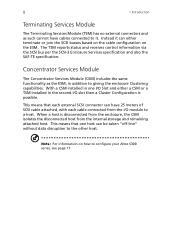
.... 8 1 Introduction Terminating Services Module The Terminating Services Module (TSM) has no external connectors and as the ESM, in the second I/O slot then a Cluster Configuration is disconnected from the enclosure, the CSM isolates the disconnected host from the I /O Slot and either terminate or join the SCSI busses based on the cable configuration on how to it can have cables connected to configure your Altos S300 series, see...
.... 8 1 Introduction Terminating Services Module The Terminating Services Module (TSM) has no external connectors and as the ESM, in the second I/O slot then a Cluster Configuration is disconnected from the enclosure, the CSM isolates the disconnected host from the I /O Slot and either terminate or join the SCSI busses based on the cable configuration on how to it can have cables connected to configure your Altos S300 series, see...
User Manual
Page 22
... before powering on the shelf. 5. Failure to reach room ambient temperature before you install or operate the Altos S300. It is intended for servicing. 8. Disconnect both power cables before opening this equipment. Disconnect both power supply inlets before servicing this equipment for installation in the area of the components are removed, the resulting hole must be at the same ground potential. 6. If any of the fan connection. 7. Warning! Warning! For...
... before powering on the shelf. 5. Failure to reach room ambient temperature before you install or operate the Altos S300. It is intended for servicing. 8. Disconnect both power cables before opening this equipment. Disconnect both power supply inlets before servicing this equipment for installation in the area of the components are removed, the resulting hole must be at the same ground potential. 6. If any of the fan connection. 7. Warning! Warning! For...

User Manual
Page 25
... loaded (where possible) from the bottom of the equipment rack upwards. Caution: When installing or removing a rack mount enclosure, remove all disk drives. This is recommended to the enclosure. In addition, surge currents must be applied. Disk drives may consume twice the amount of any other electrical devices installed in the equipment rack to ensure that you work with at least one other...
... loaded (where possible) from the bottom of the equipment rack upwards. Caution: When installing or removing a rack mount enclosure, remove all disk drives. This is recommended to the enclosure. In addition, surge currents must be applied. Disk drives may consume twice the amount of any other electrical devices installed in the equipment rack to ensure that you work with at least one other...

User Manual
Page 32
Attach the other . When viewed from front of the cable to the connector on the host connectors, refer to the documentation supplied with the host system. The length of the host cable may be a maximum of this configuration. Attach one I/O slot and a TSM in the other end of 10 meters in length. SCSI ID Assignments shown from the rear there should be...
Attach the other . When viewed from front of the cable to the connector on the host connectors, refer to the documentation supplied with the host system. The length of the host cable may be a maximum of this configuration. Attach one I/O slot and a TSM in the other end of 10 meters in length. SCSI ID Assignments shown from the rear there should be...

User Manual
Page 33
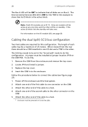
Cabling the dual (split) SCSI bus configuration Two host cables are required for the TSM in this cable to a host. Only one module will be active at ID 15. Attach one end of the cable to one I /O modules are on Bus A. When viewed from the rear there should be an ESM installed in standby mode. Note: For more information on the host connectors, refer to the documentation supplied with...
Cabling the dual (split) SCSI bus configuration Two host cables are required for the TSM in this cable to a host. Only one module will be active at ID 15. Attach one end of the cable to one I /O modules are on Bus A. When viewed from the rear there should be an ESM installed in standby mode. Note: For more information on the host connectors, refer to the documentation supplied with...

User Manual
Page 35
... host cable is required for this cable to the documentation supplied with it. To Host ID 7 1 1 2 2 Mute I 0 I 0 CSM TSM The CSM and TSM can be cabled as a Dual (Split) SCSI Bus configuration. Attach the other . Attach one I/O slot and a TSM in the other end of this configuration. When viewed from front of enclosure. Follow the procedures below ): 1. SCSI ID Assignments shown from the rear...
... host cable is required for this cable to the documentation supplied with it. To Host ID 7 1 1 2 2 Mute I 0 I 0 CSM TSM The CSM and TSM can be cabled as a Dual (Split) SCSI Bus configuration. Attach the other . Attach one I/O slot and a TSM in the other end of this configuration. When viewed from front of enclosure. Follow the procedures below ): 1. SCSI ID Assignments shown from the rear...
User Manual
Page 36
... disks are on the CSM PCB. Replace the top cover. 4. Attach the other end of 25 meters. The Environmental Services (ES) LED is the active block. Cabling the dual (split) SCSI bus configuration Two host cables are required for the TSM in to one end of this cable to a host. 4. When viewed from the enclosure and remove the top cover. 2. Insert the CSM in this configuration. Power...
... disks are on the CSM PCB. Replace the top cover. 4. Attach the other end of 25 meters. The Environmental Services (ES) LED is the active block. Cabling the dual (split) SCSI bus configuration Two host cables are required for the TSM in to one end of this cable to a host. 4. When viewed from the enclosure and remove the top cover. 2. Insert the CSM in this configuration. Power...

User Manual
Page 40
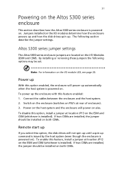
.../CSM from the ESM/CSM and locate jumper JP10. The overall cable length can be 50 meters (25 meters from each I/O module connector to the host system. The following table explains the jumper settings: i/O Module Jumper JP 10 Bus State ESMa Installed Removed 2 cables attached, bus is Force Joined Depends on c able configuration CSMb Installed Removed 2 cables attached, bus is located on it that forces the SCSI bus into joined or split mode.
.../CSM from the ESM/CSM and locate jumper JP10. The overall cable length can be 50 meters (25 meters from each I/O module connector to the host system. The following table explains the jumper settings: i/O Module Jumper JP 10 Bus State ESMa Installed Removed 2 cables attached, bus is Force Joined Depends on c able configuration CSMb Installed Removed 2 cables attached, bus is located on it that forces the SCSI bus into joined or split mode.
User Manual
Page 41
... select this feature enabled: 1. If two CSMs are installed, the jumper should be installed on both CSMs. Remote start up . To power up the enclosure with this option, the disk drives will power on ). Connect the cables between the enclosure and the host system. 2. If two CSMs are installed, the jumper should be installed on both CSMs. By installing or removing these jumpers the following section describe the jumper settings.
... select this feature enabled: 1. If two CSMs are installed, the jumper should be installed on both CSMs. Remote start up . To power up the enclosure with this option, the disk drives will power on ). Connect the cables between the enclosure and the host system. 2. If two CSMs are installed, the jumper should be installed on both CSMs. By installing or removing these jumpers the following section describe the jumper settings.
User Manual
Page 42
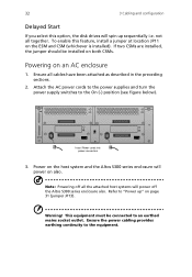
... figure below). 1 1 2 2 I 0 I 0 Mute Insert Power cords into power connectors 3. Note: Powering off all the attached host systems will spin up " on page 31 (jumper JP13). To enable this option, the disk drives will power off the Altos S300 series enclosure also. Ensure the power cabling provides earthing continuity to "Power up sequentially i.e. Attach the AC power cords to the power supplies and turn the power supply switches to an earthed mains...
... figure below). 1 1 2 2 I 0 I 0 Mute Insert Power cords into power connectors 3. Note: Powering off all the attached host systems will spin up " on page 31 (jumper JP13). To enable this option, the disk drives will power off the Altos S300 series enclosure also. Ensure the power cabling provides earthing continuity to "Power up sequentially i.e. Attach the AC power cords to the power supplies and turn the power supply switches to an earthed mains...

User Manual
Page 46
... split) SCSI bus configuration, each ES block will report enclosure information over one located on each disk drive carrier. • Monitoring/control for the microcontroller. If the other ES block detects the loss of reporting enclosure information via the SCSI bus. • Microcontroller for data processing, control, and communications. • Volatile and non-volatile memory for 2 power supplies and 4 fans (2 per ACM). • Control of 3 Front Panel system LEDs, to...
... split) SCSI bus configuration, each ES block will report enclosure information over one located on each disk drive carrier. • Monitoring/control for the microcontroller. If the other ES block detects the loss of reporting enclosure information via the SCSI bus. • Microcontroller for data processing, control, and communications. • Volatile and non-volatile memory for 2 power supplies and 4 fans (2 per ACM). • Control of 3 Front Panel system LEDs, to...

User Manual
Page 59
...). 4. Removing a disk drive carrier 1. Caution: Immediately replace the disk drive carrier or install a disk drive carrier blank to enclosure). 3. Orient the disk drive carrier such that the LEDs are on page 48, and pull the cam lever towards you. 2. Fully open the cam lever (approximately 90o to maintain correct airflow. With the cam lever open , slide the carrier into the slot until the lever starts to...
...). 4. Removing a disk drive carrier 1. Caution: Immediately replace the disk drive carrier or install a disk drive carrier blank to enclosure). 3. Orient the disk drive carrier such that the LEDs are on page 48, and pull the cam lever towards you. 2. Fully open the cam lever (approximately 90o to maintain correct airflow. With the cam lever open , slide the carrier into the slot until the lever starts to...

User Manual
Page 62
... module 1. Installing an I /O option modules (ESM and TSM) are located in the rear of the slot. Secure in page 17. Disconnect all cables connected to the I /O option module 1. Gently insert the I /O option module out of the enclosure. Using the module handle, gently slide the I /O option module into the slot. 3. Loosen the two fixing screws. 4. Follow these procedures to be removed. 3. Removing an I /O module to install and remove the module. Connect the cables...
... module 1. Installing an I /O option modules (ESM and TSM) are located in the rear of the slot. Secure in page 17. Disconnect all cables connected to the I /O option module 1. Gently insert the I /O option module out of the enclosure. Using the module handle, gently slide the I /O option module into the slot. 3. Loosen the two fixing screws. 4. Follow these procedures to be removed. 3. Removing an I /O module to install and remove the module. Connect the cables...

User Manual
Page 65
... cable length means that the sum lenght of 14 drives Redundant components • Two Environmental Services blocks located on the I/O modules (one on each). • Two power supplies. • Two advanced cooling modules. • One front LED module. • Up to 14 disk drives, removable from the front. Hot swappable components • Two power supplies, removable from the rear. • Two advanced cooling modules, removable from the rear. • One front LED module, removable...
... cable length means that the sum lenght of 14 drives Redundant components • Two Environmental Services blocks located on the I/O modules (one on each). • Two power supplies. • Two advanced cooling modules. • One front LED module. • Up to 14 disk drives, removable from the front. Hot swappable components • Two power supplies, removable from the rear. • Two advanced cooling modules, removable from the rear. • One front LED module, removable...

User Manual
Page 77
... status 36 es block, features 36 es block, master 36 F fan speed 6 fans, 6 67 features 4 H hot swappable components 55 humidity 56 J join bus jumper 30 joined scsi bus 22, 25 jumper settings 31 L leds, acm 43 leds, disk drive 40 leds, enclosure 39 leds, esm 20 leds, front panel 39 leds, i/o module 20 leds, power supply 42 leds, tsm 20 loading racks, 15 M mode of operation 19 monitoring 56 mute, alarm buzzer 38 O operating 14 option module 6, 7 install 52 remove 52 P peak power 42 power consumption...
... status 36 es block, features 36 es block, master 36 F fan speed 6 fans, 6 67 features 4 H hot swappable components 55 humidity 56 J join bus jumper 30 joined scsi bus 22, 25 jumper settings 31 L leds, acm 43 leds, disk drive 40 leds, enclosure 39 leds, esm 20 leds, front panel 39 leds, i/o module 20 leds, power supply 42 leds, tsm 20 loading racks, 15 M mode of operation 19 monitoring 56 mute, alarm buzzer 38 O operating 14 option module 6, 7 install 52 remove 52 P peak power 42 power consumption...


