
User Manual
Page 3
... logo or FCC IDE on the label. Once the class of this equipment. Class A equipment This device has been tested and found to operate this server. Operation of the device is granted by the manufacturer could void the user's authority, which case the user will be made using shielded cables to...
... logo or FCC IDE on the label. Once the class of this equipment. Class A equipment This device has been tested and found to operate this server. Operation of the device is granted by the manufacturer could void the user's authority, which case the user will be made using shielded cables to...

User Manual
Page 4
.... Laser compliance statement The CD-ROM drive in this device must accept any interference received, including interference that may not cause harmful interference, and (2) this server is located on the drive. CLASS 1 LASER PRODUCT CAUTION: INVISIBLE LASER RADIATION WHEN OPEN. AVOID EXPOSURE TO BEAM. Notice: Canadian users This Class A digital apparatus...
.... Laser compliance statement The CD-ROM drive in this device must accept any interference received, including interference that may not cause harmful interference, and (2) this server is located on the drive. CLASS 1 LASER PRODUCT CAUTION: INVISIBLE LASER RADIATION WHEN OPEN. AVOID EXPOSURE TO BEAM. Notice: Canadian users This Class A digital apparatus...
User Manual
Page 7
... 37 Turning off the system 38 3 System upgrade 39 Installation precautions 41 ESD precautions 41 Pre-installation instructions 42 Post-installation instructions 42 Opening the server 43 Removing the side panel 43 Removing the front bezel 44 Configuring the hard drive 45 Installing a 3.5"HDD cage 45 Removing a HDD cage 48 Installing...
... 37 Turning off the system 38 3 System upgrade 39 Installation precautions 41 ESD precautions 41 Pre-installation instructions 42 Post-installation instructions 42 Opening the server 43 Removing the side panel 43 Removing the front bezel 44 Configuring the hard drive 45 Installing a 3.5"HDD cage 45 Removing a HDD cage 48 Installing...

User Manual
Page 8
... Control PCI Configuration SATA Configuration I/O Device Configuration Boot Configuration Thermal and Acoustic Configuration Power Security menu Setting a system password Changing a system password Removing a system password Server menu System Management Console Redirection Event Log Configuration Boot menu Exit menu 5 System troubleshooting Resetting the system Initial system startup problems Initial troubleshooting checklist Hardware...
... Control PCI Configuration SATA Configuration I/O Device Configuration Boot Configuration Thermal and Acoustic Configuration Power Security menu Setting a system password Changing a system password Removing a system password Server menu System Management Console Redirection Event Log Configuration Boot menu Exit menu 5 System troubleshooting Resetting the system Initial system startup problems Initial troubleshooting checklist Hardware...

User Manual
Page 9
... management PC Installing the Java Tool Installing the UPnP tool Using the UPnP tool to search for an Altos server Altos eXpress Console Accessing the Altos eXpress Console Altos eXpress Console User Interface System Status System Information Server Health Configuration Remote Control Maintenance KVM Remote Console Utility Menu bar 171 173 175 175 175 176 177...
... management PC Installing the Java Tool Installing the UPnP tool Using the UPnP tool to search for an Altos server Altos eXpress Console Accessing the Altos eXpress Console Altos eXpress Console User Interface System Status System Information Server Health Configuration Remote Control Maintenance KVM Remote Console Utility Menu bar 171 173 175 175 175 176 177...

User Manual
Page 12
The Acer Altos G540 M2 server is a fully modular dual-processor system featuring the latest in computing technology. From simple networking functions to meet the needs of various network environments. It host a range of powerful and flexible features designed to computing intensive applications, the Altos G540 M2 delivers.
The Acer Altos G540 M2 server is a fully modular dual-processor system featuring the latest in computing technology. From simple networking functions to meet the needs of various network environments. It host a range of powerful and flexible features designed to computing intensive applications, the Altos G540 M2 delivers.

User Manual
Page 14
... MB video memory Networking • Integrated dual-port Gigabit Ethernet supporting Intel® I/O Acceleration Technology (IOAT) • Integrated single-port 10/100 Fast Ethernet for server management and KVM over IP remote management • Supports boot from iSCSI Media storage Two front 5.25" drive bays: • Up to eight 3.5" or sixteen...
... MB video memory Networking • Integrated dual-port Gigabit Ethernet supporting Intel® I/O Acceleration Technology (IOAT) • Integrated single-port 10/100 Fast Ethernet for server management and KVM over IP remote management • Supports boot from iSCSI Media storage Two front 5.25" drive bays: • Up to eight 3.5" or sixteen...

User Manual
Page 15
...module for hotswap and redundancy) • One system fan (can be upgraded with second system fan for redundancy) Hardware monitoring and server management • Power status LED • HDD access LED • LAN activity LED • System Status LED • System...8226; IPMI 2.0 • TPM v1.2 • Built-in Altos eXpress Console for server management and KVM over IP remote management • Acer EasyBUILD™v9.0 • Acer Server Manager (ASM) Operating system • Microsoft® Windows® Server 2008 Standard and Enterprise Edition (x86) • Microsoft® Windows...
...module for hotswap and redundancy) • One system fan (can be upgraded with second system fan for redundancy) Hardware monitoring and server management • Power status LED • HDD access LED • LAN activity LED • System Status LED • System...8226; IPMI 2.0 • TPM v1.2 • Built-in Altos eXpress Console for server management and KVM over IP remote management • Acer EasyBUILD™v9.0 • Acer Server Manager (ASM) Operating system • Microsoft® Windows® Server 2008 Standard and Enterprise Edition (x86) • Microsoft® Windows...

User Manual
Page 16
...; Red Hat® Enterprise Linux 5.0 (x86) • Red Hat® Enterprise Linux 5.0 (EM64T) • Novell® SuSE® Linux Enterprise Server 10 (x86) • Novell® SuSE® Linux Enterprise Server 10 (EM64T) • VMware ESX4i and VMware ESX4.0 • Novell® NetWare® 6.5 Mechanical • Chassis • Tower • 5U rack...
...; Red Hat® Enterprise Linux 5.0 (x86) • Red Hat® Enterprise Linux 5.0 (EM64T) • Novell® SuSE® Linux Enterprise Server 10 (x86) • Novell® SuSE® Linux Enterprise Server 10 (EM64T) • VMware ESX4i and VMware ESX4.0 • Novell® NetWare® 6.5 Mechanical • Chassis • Tower • 5U rack...

User Manual
Page 17
7 Hardware options Note: To purchase the any of the following hardware options, contact your local Acer representative. • Intel® Xeon® processor 5500 series: • 2.66 - 2.93 GHz with 8 MB shared cache, 6.40 GT/s QPI • 2.26 - 2.53 GHz with 8 ... eight-port 3 Gb SAS RAID HBA • AFC/4S single-port 4 Gb FC HBA • AFC/4D dual-port 4 Gb FC HBA • Gigabit Ethernet server adapter • PCI Express® x16 graphics card • Storage drives:
7 Hardware options Note: To purchase the any of the following hardware options, contact your local Acer representative. • Intel® Xeon® processor 5500 series: • 2.66 - 2.93 GHz with 8 MB shared cache, 6.40 GT/s QPI • 2.26 - 2.53 GHz with 8 ... eight-port 3 Gb SAS RAID HBA • AFC/4S single-port 4 Gb FC HBA • AFC/4D dual-port 4 Gb FC HBA • Gigabit Ethernet server adapter • PCI Express® x16 graphics card • Storage drives:

User Manual
Page 19
9 External and internal structure Front bezel No. Component 1 Security keylock This lock secures the bezel door to protect the server unit from unauthorized access. 2 LED indicator panel For more information on the LED indicators description, go to page 24. 3 Bezel door
9 External and internal structure Front bezel No. Component 1 Security keylock This lock secures the bezel door to protect the server unit from unauthorized access. 2 LED indicator panel For more information on the LED indicators description, go to page 24. 3 Bezel door

User Manual
Page 21
... 17 18 Component Description Power indicator Indicates the system power status (green). USB 2.0 ports Connects to USB devices. 19 Power button Press to turn the server on/off, or to secure the Hot-plug HDD. HDD bay covers Covers for preventing the system from unauthorized access. 11 No. HDD activity indicator...
... 17 18 Component Description Power indicator Indicates the system power status (green). USB 2.0 ports Connects to USB devices. 19 Power button Press to turn the server on/off, or to secure the Hot-plug HDD. HDD bay covers Covers for preventing the system from unauthorized access. 11 No. HDD activity indicator...

User Manual
Page 22
... the ID button to diskettes. This memory dump can later be analyzed to issue a non-maskable interrupt. This identifies a particular unit within a server group during servicing or maintenance procedures. 12 1 System tour No. Icon 20 21 Component Description NMI switch If the system crashes or stops normal operation..., press the NMI switch to mechanically force the server to determine the cause of the server's CPU registers and RAM to a network server or to turn on the ID LED indicator.
... the ID button to diskettes. This memory dump can later be analyzed to issue a non-maskable interrupt. This identifies a particular unit within a server group during servicing or maintenance procedures. 12 1 System tour No. Icon 20 21 Component Description NMI switch If the system crashes or stops normal operation..., press the NMI switch to mechanically force the server to determine the cause of the server's CPU registers and RAM to a network server or to turn on the ID LED indicator.

User Manual
Page 24
PS/2 keyboard Connects to monitors. port Monitor port Connects to a PS/2 keyboard. Gigabit LAN ports 1/2 Connects to mark a particular server unit within a server group (when rack-mounted) for purpose of identification during servicing or maintenance procedures. (blue) Fast Ethernet (RJ-45) port dedicated for BMC management. 14 No. ...
PS/2 keyboard Connects to monitors. port Monitor port Connects to a PS/2 keyboard. Gigabit LAN ports 1/2 Connects to mark a particular server unit within a server group (when rack-mounted) for purpose of identification during servicing or maintenance procedures. (blue) Fast Ethernet (RJ-45) port dedicated for BMC management. 14 No. ...

User Manual
Page 42
The server is designed to configure the network setup. To ensure proper operation, plug the power cord into a properly grounded AC outlet only. 32 2 System setup Connecting peripherals The color-coded I/O port panel on or pinched by items placed against it. Caution: Do not route the power cord where it will walked on the system rear accepts a variety of compatible peripherals. Refer to the figure below for specific connection instructions for information on how to be electrically grounded (earthed). Note: Consult the operating system manual for each port.
The server is designed to configure the network setup. To ensure proper operation, plug the power cord into a properly grounded AC outlet only. 32 2 System setup Connecting peripherals The color-coded I/O port panel on or pinched by items placed against it. Caution: Do not route the power cord where it will walked on the system rear accepts a variety of compatible peripherals. Refer to the figure below for specific connection instructions for information on how to be electrically grounded (earthed). Note: Consult the operating system manual for each port.
User Manual
Page 47
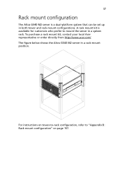
For instructions on page 157. The figure below shows the Altos G540 M2 server in both tower and rack-mount configurations. 37 Rack mount configuration The Altos G540 M2 server is available for customers who prefer to "Appendix B: Rack mount configuration" on tower-to-rack configuration, refer to mount the server in a system rack. A rack mount kit is a dual-platform system that can be set up in a rack-mount position. To purchase a rack mount kit, contact your local Acer representative or order directly from http://www.acer.com/.
For instructions on page 157. The figure below shows the Altos G540 M2 server in both tower and rack-mount configurations. 37 Rack mount configuration The Altos G540 M2 server is available for customers who prefer to "Appendix B: Rack mount configuration" on tower-to-rack configuration, refer to mount the server in a system rack. A rack mount kit is a dual-platform system that can be set up in a rack-mount position. To purchase a rack mount kit, contact your local Acer representative or order directly from http://www.acer.com/.

User Manual
Page 48
... the Windows taskbar. 2 Select Shut Down. 3 Select Shut down from the drop-down the server via software, press the power button for at least four seconds. Quickly pressing the button may put the server in a Suspend mode only. The software procedure below applies to the related user documentation. To... turn off the server-via software or via hardware. 38 2 System setup Turning off the system There are ...
... the Windows taskbar. 2 Select Shut Down. 3 Select Shut down from the drop-down the server via software, press the power button for at least four seconds. Quickly pressing the button may put the server in a Suspend mode only. The software procedure below applies to the related user documentation. To... turn off the server-via software or via hardware. 38 2 System setup Turning off the system There are ...

User Manual
Page 51
..., such as ordinary plastic assembly aids and foam packing. 41 Installation precautions Before you read the following precautions before you install a server component: • Do not remove a component from its protective packaging until you are ready to install it. • Do not...install any procedure requiring ESD protection. • Keep the work area free of the server before handling components. These sections contain important ESD precautions along with the server throughout any server component, it to a metal part of nonconductive materials, such as the processor, disk ...
..., such as ordinary plastic assembly aids and foam packing. 41 Installation precautions Before you read the following precautions before you install a server component: • Do not remove a component from its protective packaging until you are ready to install it. • Do not...install any procedure requiring ESD protection. • Keep the work area free of the server before handling components. These sections contain important ESD precautions along with the server throughout any server component, it to a metal part of nonconductive materials, such as the processor, disk ...

User Manual
Page 52
...hardware configuration may cause serious damage and bodily harm. Post-installation instructions Perform the steps below before you open the server or before you are installed according to the described step-by-step instructions. 2 Reinstall any expansion board(s), peripheral(s), ...telecommunication cables. 5 Turn on page 43. 6 Follow the ESD precautions described in the previous section when handling a server component. Failure to properly turn off the server and all connected peripherals. 2 Unplug all power cables from their outlets. 3 Disconnect all components are a qualified service...
...hardware configuration may cause serious damage and bodily harm. Post-installation instructions Perform the steps below before you open the server or before you are installed according to the described step-by-step instructions. 2 Reinstall any expansion board(s), peripheral(s), ...telecommunication cables. 5 Turn on page 43. 6 Follow the ESD precautions described in the previous section when handling a server component. Failure to properly turn off the server and all connected peripherals. 2 Unplug all power cables from their outlets. 3 Disconnect all components are a qualified service...

User Manual
Page 53
Refer to the server's internal components. Removing the side panel 1 Perform the pre-installation instructions described on page 41. 2 Unlock the security keylock. 3 Remove the two thumb screws on ... disengage it . The front bezel and (left) side panel are removable to allow access to the following sections for instructions. You need to open the server before you have turned off the system and all peripherals connected to it . 43 Opening the...
Refer to the server's internal components. Removing the side panel 1 Perform the pre-installation instructions described on page 41. 2 Unlock the security keylock. 3 Remove the two thumb screws on ... disengage it . The front bezel and (left) side panel are removable to allow access to the following sections for instructions. You need to open the server before you have turned off the system and all peripherals connected to it . 43 Opening the...


