
User Manual
Page 7
Contents Notices iii FCC notice iii Class B equipment iii Laser compliance statement iv Important safety instructions v 1 System information 1 Product briefing 3 Processor 3 Memory subsystem 3 Storage 4 Graphics interface 4 Networking 4 I/O ports 4 Serial ATA ports 4 PCI I/O 4 Caring features 5 Product specification summary 7 2 System tour 9 System board 11 Mainboard layout 11 Jumper settings ...
Contents Notices iii FCC notice iii Class B equipment iii Laser compliance statement iv Important safety instructions v 1 System information 1 Product briefing 3 Processor 3 Memory subsystem 3 Storage 4 Graphics interface 4 Networking 4 I/O ports 4 Serial ATA ports 4 PCI I/O 4 Caring features 5 Product specification summary 7 2 System tour 9 System board 11 Mainboard layout 11 Jumper settings ...

User Manual
Page 8
... heat sink 39 Connecting the processor fan heat sink cable 39 To remove a Processor 40 Upgrading the system memory 41 Memory configuration 41 To remove a DIMM 43 To install a DIMM 44 Reconfiguring the system memory 44 Installing an expansion card 45 To install an expansion card 45 Installing and removing a hard disk 47...
... heat sink 39 Connecting the processor fan heat sink cable 39 To remove a Processor 40 Upgrading the system memory 41 Memory configuration 41 To remove a DIMM 43 To install a DIMM 44 Reconfiguring the system memory 44 Installing an expansion card 45 To install an expansion card 45 Installing and removing a hard disk 47...

User Manual
Page 15
..., banking and stacking technology, and vendor should be encountered if mixed memory types are installed on the same server board. DIMM modules of your Altos G310 Mk2 system. Caution! Processor • Support for an Intel Pentium 4 processor in the Altos G310 Mk2. When using multiple memory modules it is recommended that you AVOID using modules from different manufacturers...
..., banking and stacking technology, and vendor should be encountered if mixed memory types are installed on the same server board. DIMM modules of your Altos G310 Mk2 system. Caution! Processor • Support for an Intel Pentium 4 processor in the Altos G310 Mk2. When using multiple memory modules it is recommended that you AVOID using modules from different manufacturers...

User Manual
Page 19
.../800 MHz FSB supports processor speeds from 2.8 GHz to 3.8 GHz or higher • Intel® 7221 Chipset • Intel® E7221MC Memory Controller Hub (GMCH) • Intel® 82801FR I/O Controller Hub (ICH6-R) • Four DIMM sockets supporting DDR2 400/533 MHz ECC modules for a... maximum memory capacity of 4 GB • Intel® E7221MC GMCH integrated PCI Express x8 Graphics Controller • Integrated dual-port Ethernet • Marvell®...
.../800 MHz FSB supports processor speeds from 2.8 GHz to 3.8 GHz or higher • Intel® 7221 Chipset • Intel® E7221MC Memory Controller Hub (GMCH) • Intel® 82801FR I/O Controller Hub (ICH6-R) • Four DIMM sockets supporting DDR2 400/533 MHz ECC modules for a... maximum memory capacity of 4 GB • Intel® E7221MC GMCH integrated PCI Express x8 Graphics Controller • Integrated dual-port Ethernet • Marvell®...

User Manual
Page 41
... service technician for safety purposes, we recommend that you want to a metal part of the server are upgradeable such as the drives, the CPU, the memory, and the expansion cards. 29 Upgrading the system Certain components of the server before you install a server component: 1 Do not remove a component from its protective...
... service technician for safety purposes, we recommend that you want to a metal part of the server are upgradeable such as the drives, the CPU, the memory, and the expansion cards. 29 Upgrading the system Certain components of the server before you install a server component: 1 Do not remove a component from its protective...

User Manual
Page 53
The memory modules are located on the main server board as shown below: Channel A DIMM 0 DIMM 1 Channel B DIMM 0 DIMM 1 The two tables (below) summarize the characteristics of 1-way and 2way memory interleave configurations. Memory Channel A DIMM0 512 MB 1 GB 512 MB 1 GB 512 MB 1 GB DIMM1 512 MB 1 GB Memory Channel B DIMM0 DIMM1 512 MB 1 GB 512 MB 1 GB 512 MB 1 GB Memory Interleave 1-way 2-way 2-way 41 Upgrading the system memory Memory configuration This section includes instructions for removing and installing a memory module.
The memory modules are located on the main server board as shown below: Channel A DIMM 0 DIMM 1 Channel B DIMM 0 DIMM 1 The two tables (below) summarize the characteristics of 1-way and 2way memory interleave configurations. Memory Channel A DIMM0 512 MB 1 GB 512 MB 1 GB 512 MB 1 GB DIMM1 512 MB 1 GB Memory Channel B DIMM0 DIMM1 512 MB 1 GB 512 MB 1 GB 512 MB 1 GB Memory Interleave 1-way 2-way 2-way 41 Upgrading the system memory Memory configuration This section includes instructions for removing and installing a memory module.

User Manual
Page 54
DIMM modules of identical type, banking and stacking technology, and vendor should be encountered if mixed memory types are installed on the same server board. Functionality issues may be installed in the Altos G310 Mk2. 42 4 Configuring the system Warning!
DIMM modules of identical type, banking and stacking technology, and vendor should be encountered if mixed memory types are installed on the same server board. Functionality issues may be installed in the Altos G310 Mk2. 42 4 Configuring the system Warning!

User Manual
Page 56
DM2, DM3 and DM4 Note: The DIMM socket is slotted to view the new value for total system memory and make a note of memory installed. Reverse the orientation of the DIMM and insert it again. 6 Observe the "Post-installation instructions" on the socket. 4 Align then insert the DIMM ... a DIMM but it does not fit easily into the socket (1). 5 Press the holding clips inward to lock the DIMM in place (2). Reconfiguring the system memory The system automatically detects the amount of it incorrectly. DIMMs must be installed in the following order: DM1. Run the BIOS setup to ensure proper...
DM2, DM3 and DM4 Note: The DIMM socket is slotted to view the new value for total system memory and make a note of memory installed. Reverse the orientation of the DIMM and insert it again. 6 Observe the "Post-installation instructions" on the socket. 4 Align then insert the DIMM ... a DIMM but it does not fit easily into the socket (1). 5 Press the holding clips inward to lock the DIMM in place (2). Reconfiguring the system memory The system automatically detects the amount of it incorrectly. DIMMs must be installed in the following order: DM1. Run the BIOS setup to ensure proper...

User Manual
Page 63
... system reboots immediately after you have saved all open files. Before you run this case, the system cannot retain configuration values in a battery-backed nonvolatile memory called CMOS RAM. This memory area is a hardware configuration program built into your system's Basic Input/Output System (BIOS). In this utility.
... system reboots immediately after you have saved all open files. Before you run this case, the system cannot retain configuration values in a battery-backed nonvolatile memory called CMOS RAM. This memory area is a hardware configuration program built into your system's Basic Input/Output System (BIOS). In this utility.

User Manual
Page 66
...Technology : [Enabled] Processor Speed 3.6 GHz System Bus Speed 800 MHz System Memory Speed 533 MHz Memory Mode Dual Channel Memory Channel A Slot 0 1024 MB Memory Channel A Slot 1 1024 MB ←→ Select Screen Memory Channel B Slot 0 Memory Channel B Slot 1 1024 MB 1024 MB ↑↓ Select Item Enter... Defaults F10 Save and Exit ESC Exit ▼ Parameter Hyper-Threading Technology Additional System Information Memory Correction System Time Description Enable Hyper-Threading Technology only if OS supports it Display the system information Option Enabled Disabled...
...Technology : [Enabled] Processor Speed 3.6 GHz System Bus Speed 800 MHz System Memory Speed 533 MHz Memory Mode Dual Channel Memory Channel A Slot 0 1024 MB Memory Channel A Slot 1 1024 MB ←→ Select Screen Memory Channel B Slot 0 Memory Channel B Slot 1 1024 MB 1024 MB ↑↓ Select Item Enter... Defaults F10 Save and Exit ESC Exit ▼ Parameter Hyper-Threading Technology Additional System Information Memory Correction System Time Description Enable Hyper-Threading Technology only if OS supports it Display the system information Option Enabled Disabled...

User Manual
Page 75
... BOTH 32MB/64MB/ 128MB/Maximum 63 Video Configuration Advanced Video Configuration Primary Video Adapter Frame Buffer Size IGD Aperture Size DVMT MODE IGD DVMT/FIXED MEMORY BIOS SETUP UTILITY [Auto] [ 8MB] [256MB] [DVMT] [128MB] Allows selecting the Primary Video Adapter init'd & used by BIOS & OS for use ...by the internal graphics device IGD Aperature Size Selects how much memory address space is allocated in PCI Memory space for Boot Display ←→ Select Screen ↑↓ Select Item Enter Select ?
... BOTH 32MB/64MB/ 128MB/Maximum 63 Video Configuration Advanced Video Configuration Primary Video Adapter Frame Buffer Size IGD Aperture Size DVMT MODE IGD DVMT/FIXED MEMORY BIOS SETUP UTILITY [Auto] [ 8MB] [256MB] [DVMT] [128MB] Allows selecting the Primary Video Adapter init'd & used by BIOS & OS for use ...by the internal graphics device IGD Aperature Size Selects how much memory address space is allocated in PCI Memory space for Boot Display ←→ Select Screen ↑↓ Select Item Enter Select ?

User Manual
Page 93
...installed in -depth troubleshooting, attempt first to perform a reset of the methods below. Turn the system power off /on Clear system memory, restart POST, and reload the operating system. If you are unable to the server firmware and files, also update any issue, first...or a qualified service technician for assistance. Reset button Cold boot reset. This clears system memory, restarts POST, reloads the operating system, and halts power to clear the system memory and reload the operating system. 81 Troubleshooting This chapter helps you identify and solve problems ...
...installed in -depth troubleshooting, attempt first to perform a reset of the methods below. Turn the system power off /on Clear system memory, restart POST, and reload the operating system. If you are unable to the server firmware and files, also update any issue, first...or a qualified service technician for assistance. Reset button Cold boot reset. This clears system memory, restarts POST, reloads the operating system, and halts power to clear the system memory and reload the operating system. 81 Troubleshooting This chapter helps you identify and solve problems ...

User Manual
Page 95
... the operating system normally loads from the tested components lists? Hardware diagnostic testing This section provides a more detailed approach to the system. Check the tested memory, and chassis lists, as well as the supported hardware and operating system list. Caution: Turn off devices before disconnecting cables.
... the operating system normally loads from the tested components lists? Hardware diagnostic testing This section provides a more detailed approach to the system. Check the tested memory, and chassis lists, as well as the supported hardware and operating system list. Caution: Turn off devices before disconnecting cables.

User Manual
Page 97
...cord into the same power outlet function correctly? • Some ATX power supplies have been populated according to the system requirements. • Remove the memory DIMMs and re-seat them . • Make sure the chassis standoffs are installed only below mounting holes. If your power output? • Will..., depending on your system has one at a time with a reboot between each addition. • Make sure the memory DIMMs comply with the system requirements. • Make sure the memory DIMMs have a power switch on the bottom of the power supply, next to the fan. If so, the power...
...cord into the same power outlet function correctly? • Some ATX power supplies have been populated according to the system requirements. • Remove the memory DIMMs and re-seat them . • Make sure the chassis standoffs are installed only below mounting holes. If your power output? • Will..., depending on your system has one at a time with a reboot between each addition. • Make sure the memory DIMMs comply with the system requirements. • Make sure the memory DIMMs have a power switch on the bottom of the power supply, next to the fan. If so, the power...

User Manual
Page 98
... back in one at a time with a reboot between each addition. • Make sure the memory DIMMs comply with the system requirements. • Make sure the memory DIMMs have been populated according to the system requirements. • Remove the memory DIMMs and re-seat them. • Make sure the processor(s) comply with the system...
... back in one at a time with a reboot between each addition. • Make sure the memory DIMMs comply with the system requirements. • Make sure the memory DIMMs have been populated according to the system requirements. • Remove the memory DIMMs and re-seat them. • Make sure the processor(s) comply with the system...

User Manual
Page 105
Memory fault 1- 6 Identify failing memory module DIMM end front of board Amber On = Fault POST code 1- 4 (LSB, bit1, bit2, MSB) Display boot Left rear of their use Server Management software ... = Activity. critical IDE activity Front panel Board left corner Green or Amber Press ID LED button or use is listed below. 93 LED information The Altos G310 Mk2 server system includes LEDs that can be Off, Green, Amber, Red See the POST code table Fan pack fault Warn on fan failure Front center...
Memory fault 1- 6 Identify failing memory module DIMM end front of board Amber On = Fault POST code 1- 4 (LSB, bit1, bit2, MSB) Display boot Left rear of their use Server Management software ... = Activity. critical IDE activity Front panel Board left corner Green or Amber Press ID LED button or use is listed below. 93 LED information The Altos G310 Mk2 server system includes LEDs that can be Off, Green, Amber, Red See the POST code table Fan pack fault Warn on fan failure Front center...
User Manual
Page 107
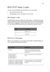
...Slave HDD Error Sec Master HDD Error Sec Slave HDD Error Could not read sector from corresponding drive. 95 BIOS POST Beep Codes The Acer Altos G310 Mk2 reports POST errors in two ways: • By sounding a beep code • By displaying an error message on the monitor ...to make sure device is not an ATAPI device. ATAPI Incompatible Corresponding drive is selected correctly. Pri Master Drive - Beep 1, 3 8 Description Memory error Video error BIOS Error Messages When a recoverable error occurs during POST if the video configuration fails (a faulty video card or no card installed...
...Slave HDD Error Sec Master HDD Error Sec Slave HDD Error Could not read sector from corresponding drive. 95 BIOS POST Beep Codes The Acer Altos G310 Mk2 reports POST errors in two ways: • By sounding a beep code • By displaying an error message on the monitor ...to make sure device is not an ATAPI device. ATAPI Incompatible Corresponding drive is selected correctly. Pri Master Drive - Beep 1, 3 8 Description Memory error Video error BIOS Error Messages When a recoverable error occurs during POST if the video configuration fails (a faulty video card or no card installed...

User Manual
Page 108
Replace the battery soon. CMOS memory may be updated. The time and/or date values stored in CMOS. Error occurred trying to reset values. Keyboard interface test failed. The display type ...
Replace the battery soon. CMOS memory may be updated. The time and/or date values stored in CMOS. Error occurred trying to reset values. Keyboard interface test failed. The display type ...

User Manual
Page 109
...Parity Error A parity error occurred on an offboard card. This error is followed by an address. Memory Size Changed Memory size has changed since the last boot. If no memory was added, there may be bad. This error is followed by Jumper NVRAM, CMOS, and passwords... Error A parity error occurred in onboard memory at an unknown address. Pressed CMOS is ignored and NVRAM is cleared. 97 Error Message Explanation Memory Size Decreased Memory size has decreased since the last boot. If no memory was removed, then memory may be powered down and the jumper ...
...Parity Error A parity error occurred on an offboard card. This error is followed by an address. Memory Size Changed Memory size has changed since the last boot. If no memory was added, there may be bad. This error is followed by Jumper NVRAM, CMOS, and passwords... Error A parity error occurred in onboard memory at an unknown address. Pressed CMOS is ignored and NVRAM is cleared. 97 Error Message Explanation Memory Size Decreased Memory size has decreased since the last boot. If no memory was removed, then memory may be powered down and the jumper ...

User Manual
Page 113
...on each logical drive • ability to select a logical drive as boot device • support for power-on self test (POST) Memory Management (PMM) for the BIOS memory requirement (Specification v1.01, November 21, 1997) • enhanced disk drive support (Specification 2.9, revision 08, March 12, 1998) &#... notification at POST • run-time BIOS support for device insertion or removal • independent support for WC, RC, and UDMA (direct memory access) • support for BIOS Boot Specification (BBS) (If available in system BIOS, this allows the user to select the adaptor from which...
...on each logical drive • ability to select a logical drive as boot device • support for power-on self test (POST) Memory Management (PMM) for the BIOS memory requirement (Specification v1.01, November 21, 1997) • enhanced disk drive support (Specification 2.9, revision 08, March 12, 1998) &#... notification at POST • run-time BIOS support for device insertion or removal • independent support for WC, RC, and UDMA (direct memory access) • support for BIOS Boot Specification (BBS) (If available in system BIOS, this allows the user to select the adaptor from which...
