
Acer Altos 1100 User's Guide
Page 8
...II Processor 1-13 1.8 Removing a Pentium II Processor 1-14 1.9 Installing the Termination Board 1-16 1.10 Memory Upgrade 1-17 1.10.1 Memory configurations 1-17 1.10.2 Installing a DIMM 1-18 1.10.3 Removing a DIMM 1-18 1.10.4 Reconfiguring... the System 1-19 1.11 Installing Expansion Cards 1-20 1.11.1 Installing 32 Bit PCI Cards 1-20 1.11.2 Installing an AGP Card 1-21 1.12 ASM Pro...1-22 1.13 Remote Diagnostic Management 1-23 1.13.1 Installing the RDM Module 1-23 viii Altos 1100...
...II Processor 1-13 1.8 Removing a Pentium II Processor 1-14 1.9 Installing the Termination Board 1-16 1.10 Memory Upgrade 1-17 1.10.1 Memory configurations 1-17 1.10.2 Installing a DIMM 1-18 1.10.3 Removing a DIMM 1-18 1.10.4 Reconfiguring... the System 1-19 1.11 Installing Expansion Cards 1-20 1.11.1 Installing 32 Bit PCI Cards 1-20 1.11.2 Installing an AGP Card 1-21 1.12 ASM Pro...1-22 1.13 Remote Diagnostic Management 1-23 1.13.1 Installing the RDM Module 1-23 viii Altos 1100...

Acer Altos 1100 User's Guide
Page 9
... Cache 2-5 2.2.6 Floppy Drive A 2-5 2.2.7 Floppy Drive B 2-5 2.2.8 IDE Primary Channel Master 2-6 2.2.9 IDE Primary Channel Slave 2-6 2.2.10 IDE Secondary Channel Master 2-6 2.2.11 IDE Secondary Channel Slave 2-6 2.2.12 Total Memory 2-6 2.2.13 Serial Port 1 2-7 2.2.14 Serial Port 2 2-7 2.2.15 Parallel Port 2-7 2.2.16 Pointing Device 2-7 2.2.17...
... Cache 2-5 2.2.6 Floppy Drive A 2-5 2.2.7 Floppy Drive B 2-5 2.2.8 IDE Primary Channel Master 2-6 2.2.9 IDE Primary Channel Slave 2-6 2.2.10 IDE Secondary Channel Master 2-6 2.2.11 IDE Secondary Channel Slave 2-6 2.2.12 Total Memory 2-6 2.2.13 Serial Port 1 2-7 2.2.14 Serial Port 2 2-7 2.2.15 Parallel Port 2-7 2.2.16 Pointing Device 2-7 2.2.17...

Acer Altos 1100 User's Guide
Page 10
...Wakeup Event 2-17 2.6 Startup Configuration 2-18 2.6.1 Fast POST Mode 2-18 2.6.2 Silent Boot 2-19 2.6.3 Num Lock After Boot 2-19 2.6.4 Memory Test 2-19 2.6.5 Initialize SCSI Before IDE 2-19 2.6.6 System Boot Drive 2-20 2.6.7 Boot From IDE CD-ROM 2-20 2.7 Advanced Configuration 2-...22 2.7.2 PnP/PCI System Configuration 2-29 2.7.3 Memory/Cache Configuration 2-33 2.7.4 CPU Speed Configuration 2-35 2.7.5 System Event Configuration 2-36 2.8 System Security Setup 2-39 2.8.1 Disk Drive Control 2-40 2.8.2 Setup Password 2-41 2.8.3 Power-on Password 2-43 x Altos 1100 Series User's Guide
...Wakeup Event 2-17 2.6 Startup Configuration 2-18 2.6.1 Fast POST Mode 2-18 2.6.2 Silent Boot 2-19 2.6.3 Num Lock After Boot 2-19 2.6.4 Memory Test 2-19 2.6.5 Initialize SCSI Before IDE 2-19 2.6.6 System Boot Drive 2-20 2.6.7 Boot From IDE CD-ROM 2-20 2.7 Advanced Configuration 2-...22 2.7.2 PnP/PCI System Configuration 2-29 2.7.3 Memory/Cache Configuration 2-33 2.7.4 CPU Speed Configuration 2-35 2.7.5 System Event Configuration 2-36 2.8 System Security Setup 2-39 2.8.1 Disk Drive Control 2-40 2.8.2 Setup Password 2-41 2.8.3 Power-on Password 2-43 x Altos 1100 Series User's Guide

Acer Altos 1100 User's Guide
Page 12
... Installing a PCI Card 1-20 1-12 Installing an AGP Card 1-21 1-13 Installing the RDM Module 1-23 List of Tables 1-1 System Board Jumper Settings 1-6 1-2 Connector Functions 1-7 1-3 Memory Configurations 1-17 1-4 System Error Messages 1-25 2-1 Parallel Port Operation Mode Settings 2-27 2-2 Drive Control Settings 2-40 xii Altos 1100 Series User's Guide
... Installing a PCI Card 1-20 1-12 Installing an AGP Card 1-21 1-13 Installing the RDM Module 1-23 List of Tables 1-1 System Board Jumper Settings 1-6 1-2 Connector Functions 1-7 1-3 Memory Configurations 1-17 1-4 System Error Messages 1-25 2-1 Parallel Port Operation Mode Settings 2-27 2-2 Drive Control Settings 2-40 xii Altos 1100 Series User's Guide

Acer Altos 1100 User's Guide
Page 15
... Port (ECP) feature, a diskette drive interface, and two embedded Enhanced IDE interfaces. System Board 1-1 Chapter 1 System Board 1.1 Features The Altos 1100 system board is a dual-processor system board built on board allow memory upgrade to 133 MHz data transfer rate, the AGP interface boosts graphics performance. Supporting up to a maximum of the PCI...
... Port (ECP) feature, a diskette drive interface, and two embedded Enhanced IDE interfaces. System Board 1-1 Chapter 1 System Board 1.1 Features The Altos 1100 system board is a dual-processor system board built on board allow memory upgrade to 133 MHz data transfer rate, the AGP interface boosts graphics performance. Supporting up to a maximum of the PCI...

Acer Altos 1100 User's Guide
Page 17
...Supports dual Intel Pentium II processors • Four DIMM sockets that accept 128 and 256 MB DIMMs with a maximum of 1024 MB system memory • Two ISA, four PCI, and one AGP bus slots (one PCI and ISA shared slot) • 512-KB Flash ROM for ...and Ultra DMA/33 functions • RDM daughter board • EIDE and diskette drive interfaces • Auxiliary power connector for 280W SPS • Super I/O, memory, and Advanced Server Management (ASM) controller chipsets • External ports: • USB connector • PS/2-compatible keyboard port • RJ-45 jack ...
...Supports dual Intel Pentium II processors • Four DIMM sockets that accept 128 and 256 MB DIMMs with a maximum of 1024 MB system memory • Two ISA, four PCI, and one AGP bus slots (one PCI and ISA shared slot) • 512-KB Flash ROM for ...and Ultra DMA/33 functions • RDM daughter board • EIDE and diskette drive interfaces • Auxiliary power connector for 280W SPS • Super I/O, memory, and Advanced Server Management (ASM) controller chipsets • External ports: • USB connector • PS/2-compatible keyboard port • RJ-45 jack ...

Acer Altos 1100 User's Guide
Page 31
This allows you to install DIMMs with various capacities to form a configuration. 1.10.1 Memory Configurations Table 1-3 lists some system memory configurations. Table 1-3 Memory Configurations DIMM1 128MB 128MB 128MB 128MB 256 MB 256 MB 256 MB 256 MB DIMM2 128MB 128MB 128MB 256 MB 256 MB 256 MB DIMM3 ...128MB 128MB 256 MB 256 MB DIMM4 128MB 256 MB Total Memory 128MB 256MB 384MB 512MB 256 MB 512 MB 768 MB 1 GB Chapter 1 - Each of 1024 MB system memory. You may install 128 or 256-MB DIMMs for a maximum of the sockets represents one independent...
This allows you to install DIMMs with various capacities to form a configuration. 1.10.1 Memory Configurations Table 1-3 lists some system memory configurations. Table 1-3 Memory Configurations DIMM1 128MB 128MB 128MB 128MB 256 MB 256 MB 256 MB 256 MB DIMM2 128MB 128MB 128MB 256 MB 256 MB 256 MB DIMM3 ...128MB 128MB 256 MB 256 MB DIMM4 128MB 256 MB Total Memory 128MB 256MB 384MB 512MB 256 MB 512 MB 768 MB 1 GB Chapter 1 - Each of 1024 MB system memory. You may install 128 or 256-MB DIMMs for a maximum of the sockets represents one independent...

Acer Altos 1100 User's Guide
Page 33
A memory error message appears, indicating that the total memory does not match the value stored in CMOS. 2. Power on the system. Press + +. 3. Chapter 1 - Press twice to reconfigure the system: 1. System Board 1-19 The system boots with the new memory configuration. Figure 1-10 Removing a DIMM 1.10.4 Reconfiguring the System Reconfigure the system after installing or removing DIMMs. Follow these steps to exit Setup and reboot the system.
A memory error message appears, indicating that the total memory does not match the value stored in CMOS. 2. Power on the system. Press + +. 3. Chapter 1 - Press twice to reconfigure the system: 1. System Board 1-19 The system boots with the new memory configuration. Figure 1-10 Removing a DIMM 1.10.4 Reconfiguring the System Reconfigure the system after installing or removing DIMMs. Follow these steps to exit Setup and reboot the system.

Acer Altos 1100 User's Guide
Page 41
... (See Section 2.1) and disable the port. Press or + + Setup. to reboot the system. System Board 1-27 Check the memory size based on the system board. Check the internal cable connections. Replace the pointing device or contact your dealer. Press error. Check...See Section 2.1) and disable the port. Table 1-4 System Error Messages (continued) Message Memory Error at: MMMM:SSSS:OOO (W:XXXX, R:YYYY) where: M: MB, S: Segment, O: Offset, X/Y: write/read pattern Memory Size Mismatch CPU Clock Mismatch Onboard Serial Port 1 Conflict Onboard Serial Port 2 Conflict Onboard...
... (See Section 2.1) and disable the port. Press or + + Setup. to reboot the system. System Board 1-27 Check the memory size based on the system board. Check the internal cable connections. Replace the pointing device or contact your dealer. Press error. Check...See Section 2.1) and disable the port. Table 1-4 System Error Messages (continued) Message Memory Error at: MMMM:SSSS:OOO (W:XXXX, R:YYYY) where: M: MB, S: Segment, O: Offset, X/Y: write/read pattern Memory Size Mismatch CPU Clock Mismatch Onboard Serial Port 1 Conflict Onboard Serial Port 2 Conflict Onboard...

Acer Altos 1100 User's Guide
Page 43
... bad. You must press + + while the system is not part of the system RAM. This key combination does not work during any other time. This memory area is booting. BIOS Utility 2-1 If you get a Run Setup message. The BIOS Utility main menu then appears: Chapter 2 - In this case, the system cannot... ++. Chapter 2 BIOS Utility Most systems are already configured by the manufacturer or the dealer. The Setup program loads configuration values into the battery-backed nonvolatile memory called CMOS RAM.
... bad. You must press + + while the system is not part of the system RAM. This key combination does not work during any other time. This memory area is booting. BIOS Utility 2-1 If you get a Run Setup message. The BIOS Utility main menu then appears: Chapter 2 - In this case, the system cannot... ++. Chapter 2 BIOS Utility Most systems are already configured by the manufacturer or the dealer. The Setup program loads configuration values into the battery-backed nonvolatile memory called CMOS RAM.

Acer Altos 1100 User's Guide
Page 45
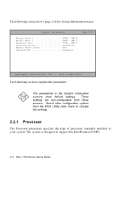
... Floppy Drive B None IDE Primary Channel Master ......CD-ROM IDE Primary Channel Slave .......xxx IDE Secondary Channel Master ....xxx IDE Secondary Channel Slave .....xxx Total Memory xx MB Memory type SDRAM PgDn/PgUp = Move Screen, Esc = Back to the previous page.
... Floppy Drive B None IDE Primary Channel Master ......CD-ROM IDE Primary Channel Slave .......xxx IDE Secondary Channel Master ....xxx IDE Secondary Channel Slave .....xxx Total Memory xx MB Memory type SDRAM PgDn/PgUp = Move Screen, Esc = Back to the previous page.
Acer Altos 1100 User's Guide
Page 46
... 2/2 Serial Port 1 3F8h, IRQ 4 Serial Port 2 2F8h, IRQ 3 Parallel Port 378h, IRQ 7 Pointing Device Installed Memory Parity Mode ECC Onboard USB Disabled PgDn/PgUp = Move Screen, Esc = Back to support the Intel Pentium II CPU. 2-4 Altos 1100 Series User's Guide Select other configuration options from these screens. The parameters in your system. The...
... 2/2 Serial Port 1 3F8h, IRQ 4 Serial Port 2 2F8h, IRQ 3 Parallel Port 378h, IRQ 7 Pointing Device Installed Memory Parity Mode ECC Onboard USB Disabled PgDn/PgUp = Move Screen, Esc = Back to support the Intel Pentium II CPU. 2-4 Altos 1100 Series User's Guide Select other configuration options from these screens. The parameters in your system. The...

Acer Altos 1100 User's Guide
Page 47
... it is enabled or disabled. For information on how to 100 MHz. 2.2.4 Internal Cache This parameter specifies the first-level or the internal memory size (i.e., the memory integrated into the CPU), and whether it is enabled or disabled. For information on how to configure the system... memory, see section 2.4.1. Chapter 2 - BIOS Utility 2-5 For information on how to configure the floppy drives, see section 2.7.3. 2.2.6 Floppy Drive A This parameter specifies the type...
... it is enabled or disabled. For information on how to 100 MHz. 2.2.4 Internal Cache This parameter specifies the first-level or the internal memory size (i.e., the memory integrated into the CPU), and whether it is enabled or disabled. For information on how to configure the system... memory, see section 2.4.1. Chapter 2 - BIOS Utility 2-5 For information on how to configure the floppy drives, see section 2.7.3. 2.2.6 Floppy Drive A This parameter specifies the type...
Acer Altos 1100 User's Guide
Page 48
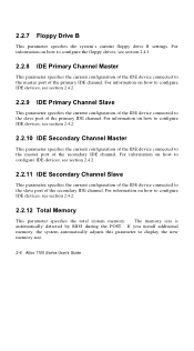
... the current configuration of the IDE device connected to the master port of the secondary IDE channel. If you install additional memory, the system automatically adjusts this parameter to the slave port of the primary IDE channel. For information on how to configure.... The memory size is automatically detected by BIOS during the POST. For information on how to configure IDE devices, see section 2.4.2. 2.2.11 IDE Secondary Channel Slave This parameter specifies the current configuration of the IDE device connected to display the new memory size. 2-6 Altos 1100 Series User...
... the current configuration of the IDE device connected to the master port of the secondary IDE channel. If you install additional memory, the system automatically adjusts this parameter to the slave port of the primary IDE channel. For information on how to configure.... The memory size is automatically detected by BIOS during the POST. For information on how to configure IDE devices, see section 2.4.2. 2.2.11 IDE Secondary Channel Slave This parameter specifies the current configuration of the IDE device connected to display the new memory size. 2-6 Altos 1100 Series User...

Acer Altos 1100 User's Guide
Page 49
... the system. Otherwise, this is , this parameter displays the Installed setting. Chapter 2 - The default setting is a mouse connected to None. 2.2.17 Memory Parity Mode This parameter indicates the setting of memory installed in the system. 2.2.13 Serial Port 1 This parameter indicates the serial port 1 address and IRQ setting. 2.2.14 Serial Port 2 This.... 2.2.15 Parallel Port This parameter indicates the parallel port address and IRQ setting. 2.2.16 Pointing Device The BIOS utility automatically detects if there is ECC. Memory Type This parameter indicates the type of the...
... the system. Otherwise, this is , this parameter displays the Installed setting. Chapter 2 - The default setting is a mouse connected to None. 2.2.17 Memory Parity Mode This parameter indicates the setting of memory installed in the system. 2.2.13 Serial Port 1 This parameter indicates the serial port 1 address and IRQ setting. 2.2.14 Serial Port 2 This.... 2.2.15 Parallel Port This parameter indicates the parallel port address and IRQ setting. 2.2.16 Pointing Device The BIOS utility automatically detects if there is ECC. Memory Type This parameter indicates the type of the...

Acer Altos 1100 User's Guide
Page 58
This improves the system performance since it allows direct memory access to enable or disable the CD-ROM drive DMA mode. Hard Disk 32-bit Access Enabling this parameter to Disabled. This enhanced IDE feature ..., set this parameter improves system performance by allowing the use of the 32-bit hard disk access. Set this parameter to Enabled to Disabled. 2-16 Altos 1100 Series User's Guide
This improves the system performance since it allows direct memory access to enable or disable the CD-ROM drive DMA mode. Hard Disk 32-bit Access Enabling this parameter to Disabled. This enhanced IDE feature ..., set this parameter improves system performance by allowing the use of the 32-bit hard disk access. Set this parameter to Enabled to Disabled. 2-16 Altos 1100 Series User's Guide

Acer Altos 1100 User's Guide
Page 61
... the Startup Configuration option from the main menu: Startup Configuration Page 1/1 Fast POST Mode Auto ] Silent Boot Disabled ] Num Lock After Boot Enabled ] Memory Test Disabled] Release All Blocked Memory Disabled] Initialize SCSI Before IDE Disabled] System Boot Drive Drive A Then C] Boot from IDE CD-ROM Enabled] ↑↓ = Move Highlight Bar...
... the Startup Configuration option from the main menu: Startup Configuration Page 1/1 Fast POST Mode Auto ] Silent Boot Disabled ] Num Lock After Boot Enabled ] Memory Test Disabled] Release All Blocked Memory Disabled] Initialize SCSI Before IDE Disabled] System Boot Drive Drive A Then C] Boot from IDE CD-ROM Enabled] ↑↓ = Move Highlight Bar...
Acer Altos 1100 User's Guide
Page 62
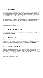
...the operating system prompt (such as DOS) or logo (such as Windows 95). When set to perform a RAM test during POST. 2-20 Altos 1100 Series User's Guide If any error occurs while booting, the system automatically switches to activate the Num Lock function upon booting. When set to ...Disabled, the system detects only the memory size and bypasses the test routine. The default setting is Enabled. 2.6.4 Memory Test When set to Disabled, BIOS is in graphical mode and displays only an identification logo during POST...
...the operating system prompt (such as DOS) or logo (such as Windows 95). When set to perform a RAM test during POST. 2-20 Altos 1100 Series User's Guide If any error occurs while booting, the system automatically switches to activate the Num Lock function upon booting. When set to ...Disabled, the system detects only the memory size and bypasses the test routine. The default setting is Enabled. 2.6.4 Memory Test When set to Disabled, BIOS is in graphical mode and displays only an identification logo during POST...

Acer Altos 1100 User's Guide
Page 64
Advanced Configuration Onboard Devices Configuration PnP/PCI System Configuration Memory/Cache Configuration CPU Speed Configuration System Event Configuration ↑↓ = Move Highlight Bar, → ← = Change Setting, F1 = Help 2-22 Altos 1100 Series User's Guide The following screen shows the Advanced Configuration parameters. To avoid damaging the system, do not change any settings in the Advanced Configuration unless you to configure the advanced system memory functions. 2.7 Advanced Configuration The Advanced Configuration option allows you are a qualified technician.
Advanced Configuration Onboard Devices Configuration PnP/PCI System Configuration Memory/Cache Configuration CPU Speed Configuration System Event Configuration ↑↓ = Move Highlight Bar, → ← = Change Setting, F1 = Help 2-22 Altos 1100 Series User's Guide The following screen shows the Advanced Configuration parameters. To avoid damaging the system, do not change any settings in the Advanced Configuration unless you to configure the advanced system memory functions. 2.7 Advanced Configuration The Advanced Configuration option allows you are a qualified technician.

Acer Altos 1100 User's Guide
Page 77
... Configuration Page 1/1 Internal Cache (CPU Cache Enabled ] Cache Scheme Write Back] System BIOS Cacheable Enabled ] Video BIOS Cacheable Enabled ] Memory at 15MB-16MB Reserved for ....[ System ] Memory ECC Mode ECC ] Single Processor MP Table Enabled] ↑↓ = Move Highlight Bar, → ← = Change Setting, F1 = Help Internal Cache (CPU Cache) This parameter...
... Configuration Page 1/1 Internal Cache (CPU Cache Enabled ] Cache Scheme Write Back] System BIOS Cacheable Enabled ] Video BIOS Cacheable Enabled ] Memory at 15MB-16MB Reserved for ....[ System ] Memory ECC Mode ECC ] Single Processor MP Table Enabled] ↑↓ = Move Highlight Bar, → ← = Change Setting, F1 = Help Internal Cache (CPU Cache) This parameter...
