
Acer Altos 1100 User's Guide
Page 8
... 1-11 1.6.3 Post-installation Instructions 1-12 1.7 Installing the Pentium II Processor 1-13 1.8 Removing a Pentium II Processor 1-14 1.9 Installing the Termination Board 1-16 1.10 Memory Upgrade 1-17 1.10.1 Memory configurations 1-17 1.10.2 Installing a DIMM 1-18 1.10.3 Removing a DIMM 1-18 1.10.4 Reconfiguring the System 1-19 1.11 Installing Expansion Cards 1-20 1.11.1 Installing 32 Bit PCI Cards 1-20 1.11.2 Installing an AGP Card 1-21 1.12 ASM Pro...1-22 1.13 Remote Diagnostic Management 1-23 1.13.1 Installing the RDM Module 1-23 viii Altos 1100 Series User's Guide
... 1-11 1.6.3 Post-installation Instructions 1-12 1.7 Installing the Pentium II Processor 1-13 1.8 Removing a Pentium II Processor 1-14 1.9 Installing the Termination Board 1-16 1.10 Memory Upgrade 1-17 1.10.1 Memory configurations 1-17 1.10.2 Installing a DIMM 1-18 1.10.3 Removing a DIMM 1-18 1.10.4 Reconfiguring the System 1-19 1.11 Installing Expansion Cards 1-20 1.11.1 Installing 32 Bit PCI Cards 1-20 1.11.2 Installing an AGP Card 1-21 1.12 ASM Pro...1-22 1.13 Remote Diagnostic Management 1-23 1.13.1 Installing the RDM Module 1-23 viii Altos 1100 Series User's Guide

Acer Altos 1100 User's Guide
Page 10
... 2-18 2.6.1 Fast POST Mode 2-18 2.6.2 Silent Boot 2-19 2.6.3 Num Lock After Boot 2-19 2.6.4 Memory Test 2-19 2.6.5 Initialize SCSI Before IDE 2-19 2.6.6 System Boot Drive 2-20 2.6.7 Boot From IDE CD-ROM 2-20 2.7 Advanced Configuration 2-21 2.7.1 Onboard Devices Configuration 2-22 2.7.2 PnP/PCI System Configuration 2-29 2.7.3 Memory/Cache Configuration 2-33 2.7.4 CPU Speed Configuration 2-35 2.7.5 System Event Configuration 2-36 2.8 System Security Setup 2-39 2.8.1 Disk Drive Control 2-40 2.8.2 Setup Password 2-41 2.8.3 Power-on Password 2-43 x Altos 1100 Series User's Guide
... 2-18 2.6.1 Fast POST Mode 2-18 2.6.2 Silent Boot 2-19 2.6.3 Num Lock After Boot 2-19 2.6.4 Memory Test 2-19 2.6.5 Initialize SCSI Before IDE 2-19 2.6.6 System Boot Drive 2-20 2.6.7 Boot From IDE CD-ROM 2-20 2.7 Advanced Configuration 2-21 2.7.1 Onboard Devices Configuration 2-22 2.7.2 PnP/PCI System Configuration 2-29 2.7.3 Memory/Cache Configuration 2-33 2.7.4 CPU Speed Configuration 2-35 2.7.5 System Event Configuration 2-36 2.8 System Security Setup 2-39 2.8.1 Disk Drive Control 2-40 2.8.2 Setup Password 2-41 2.8.3 Power-on Password 2-43 x Altos 1100 Series User's Guide

Acer Altos 1100 User's Guide
Page 12
... Processor 1-13 1-5 Securing the Pentium II Processor 1-14 1-6 Unlocking the Module Latches 1-14 1-7 Removing the Pentium II Processor 1-15 1-8 Installing the Termination Board 1-16 1-9 Installing a DIMM 1-18 1-10 Removing a DIMM 1-19 1-11 Installing a PCI Card 1-20 1-12 Installing an AGP Card 1-21 1-13 Installing the RDM Module 1-23 List of Tables 1-1 System Board Jumper Settings 1-6 1-2 Connector Functions 1-7 1-3 Memory Configurations 1-17 1-4 System Error Messages 1-25 2-1 Parallel Port Operation Mode Settings 2-27 2-2 Drive Control Settings 2-40 xii Altos 1100 Series User...
... Processor 1-13 1-5 Securing the Pentium II Processor 1-14 1-6 Unlocking the Module Latches 1-14 1-7 Removing the Pentium II Processor 1-15 1-8 Installing the Termination Board 1-16 1-9 Installing a DIMM 1-18 1-10 Removing a DIMM 1-19 1-11 Installing a PCI Card 1-20 1-12 Installing an AGP Card 1-21 1-13 Installing the RDM Module 1-23 List of Tables 1-1 System Board Jumper Settings 1-6 1-2 Connector Functions 1-7 1-3 Memory Configurations 1-17 1-4 System Error Messages 1-25 2-1 Parallel Port Operation Mode Settings 2-27 2-2 Drive Control Settings 2-40 xii Altos 1100 Series User...

Acer Altos 1100 User's Guide
Page 17
... with battery backup • I/O APIC device that provides support for SMP interrupts • Integrates an enhanced PCI local bus IDE controller • Intel 440BX chipset that supports AGP (Accelerated Graphics Port) and Ultra DMA/33 functions • RDM daughter board • EIDE and diskette drive interfaces • Auxiliary power connector for 280W SPS • Super I/O, memory, and Advanced Server Management (ASM) controller chipsets • External ports: • USB connector •...
... with battery backup • I/O APIC device that provides support for SMP interrupts • Integrates an enhanced PCI local bus IDE controller • Intel 440BX chipset that supports AGP (Accelerated Graphics Port) and Ultra DMA/33 functions • RDM daughter board • EIDE and diskette drive interfaces • Auxiliary power connector for 280W SPS • Super I/O, memory, and Advanced Server Management (ASM) controller chipsets • External ports: • USB connector •...
Acer Altos 1100 User's Guide
Page 25
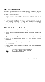
... it . 2. Turn off the system power and all the peripherals connected to the unit before opening it to a metal part of the system unit before handling a system component. 4. 1.6.1 ESD Precautions Electrostatic discharge (ESD) can damage your processor, disk drives, expansion boards, and other components. Follow the ESD precautions in the following sections for specific instructions on the component you are a qualified service technician...
... it . 2. Turn off the system power and all the peripherals connected to the unit before opening it to a metal part of the system unit before handling a system component. 4. 1.6.1 ESD Precautions Electrostatic discharge (ESD) can damage your processor, disk drives, expansion boards, and other components. Follow the ESD precautions in the following sections for specific instructions on the component you are a qualified service technician...

Acer Altos 1100 User's Guide
Page 37
... RDM connectors. 2. Connect the RDM LED. In the event of failure, RDM monitors and analyzes the server condition, updates the BIOS settings if necessary, reboots the server, and quickly returns it into CN30 and CN33. This capability to execute the RDM functions from a remote station. Do not force it to normal operation. Gently insert the RDM module into the connectors. 3. 1.13 Remote Diagnostic Management Remote Diagnostic Manager (RDM) is a server management tool that uses modems...
... RDM connectors. 2. Connect the RDM LED. In the event of failure, RDM monitors and analyzes the server condition, updates the BIOS settings if necessary, reboots the server, and quickly returns it into CN30 and CN33. This capability to execute the RDM functions from a remote station. Do not force it to normal operation. Gently insert the RDM module into the connectors. 3. 1.13 Remote Diagnostic Management Remote Diagnostic Manager (RDM) is a server management tool that uses modems...
Acer Altos 1100 User's Guide
Page 40
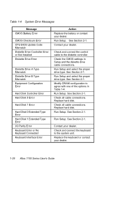
.... Table 1-4 System Error Messages Message CMOS Battery Error CMOS Checksum Error CPU BIOS Update Code Mismatch Diskette Drive Controller Error or Not Installed Diskette Drive Error Diskette Drive A Type Mismatch Diskette Drive B Type Mismatch Equipment Configuration Error Hard Disk Controller Error Hard Disk 0 Error Hard Disk 1 Error Hard Disk 0 Extended Type Error Hard Disk 1 Extended Type Error I/O Parity Error Keyboard Error or No Keyboard Connected Keyboard Interface Error Action Replace the battery or contact your dealer. 1-26 Altos 1100 Series User's Guide Replace the keyboard or...
.... Table 1-4 System Error Messages Message CMOS Battery Error CMOS Checksum Error CPU BIOS Update Code Mismatch Diskette Drive Controller Error or Not Installed Diskette Drive Error Diskette Drive A Type Mismatch Diskette Drive B Type Mismatch Equipment Configuration Error Hard Disk Controller Error Hard Disk 0 Error Hard Disk 1 Error Hard Disk 0 Extended Type Error Hard Disk 1 Extended Type Error I/O Parity Error Keyboard Error or No Keyboard Connected Keyboard Interface Error Action Replace the battery or contact your dealer. 1-26 Altos 1100 Series User's Guide Replace the keyboard or...

Acer Altos 1100 User's Guide
Page 42
... more likely to continue," it is correctly configured. If you go through the corrective steps above and still receive an error message, the cause may lie in . An incorrect configuration is a major cause of power-on the system board and any expansion boards are correct and your configuration values are set correctly (see section 1.4 for assistance. 1-28 Altos 1100 Series User's Guide Run Setup (See section 2.1).
... more likely to continue," it is correctly configured. If you go through the corrective steps above and still receive an error message, the cause may lie in . An incorrect configuration is a major cause of power-on the system board and any expansion boards are correct and your configuration values are set correctly (see section 1.4 for assistance. 1-28 Altos 1100 Series User's Guide Run Setup (See section 2.1).

Acer Altos 1100 User's Guide
Page 44
These values may not be the same as those in your system. 2-2 Altos 1100 Series User's Guide BIOS Utility System Information Product Information Disk Drives Power Management Startup Configuration Advanced Configuration System Security Date and Time Remote Diagnostic Configuration Load Default Settings Abort Settings Change Move highlight bar, ↵ = Select, Esc = Exit The parameters on the screens show default values.
These values may not be the same as those in your system. 2-2 Altos 1100 Series User's Guide BIOS Utility System Information Product Information Disk Drives Power Management Startup Configuration Advanced Configuration System Security Date and Time Remote Diagnostic Configuration Load Default Settings Abort Settings Change Move highlight bar, ↵ = Select, Esc = Exit The parameters on the screens show default values.
Acer Altos 1100 User's Guide
Page 57
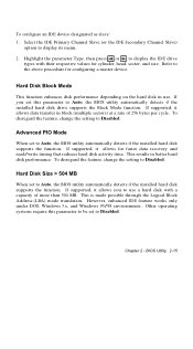
... Address (LBA) mode translation. Highlight the parameter Type, then press or to Disabled. Hard Disk Block Mode This function enhances disk performance depending on the hard disk in use a hard disk with their respective values for configuring a master device. If supported, it allows for faster data recovery and read/write timing that reduces hard disk activity time. Advanced PIO Mode When set to Auto, the BIOS utility automatically detects if the installed hard disk supports the function. Other operating systems require...
... Address (LBA) mode translation. Highlight the parameter Type, then press or to Disabled. Hard Disk Block Mode This function enhances disk performance depending on the hard disk in use a hard disk with their respective values for configuring a master device. If supported, it allows for faster data recovery and read/write timing that reduces hard disk activity time. Advanced PIO Mode When set to Auto, the BIOS utility automatically detects if the installed hard disk supports the function. Other operating systems require...

Acer Altos 1100 User's Guide
Page 59
... default settings: Power Management Page 1/1 Power Management Mode Disabled] IDE Hard Disk Standby Timer System Sleep Timer Stop CPU Clock in Sleep State ....[---] Power Switch < 4 sec Power Off] Wakeup Event Modem Ring Disabled] ↑↓ = Move Highlight Bar, → ← = Change Setting, F1 = Help 2.5.1 Power Management Mode This parameter allows you can configure the IDE hard disk and system timers. When this parameter is set to 15 minutes, depending on your setting. BIOS Utility 2-17 2.5 Power Management The Power Management menu lets you access...
... default settings: Power Management Page 1/1 Power Management Mode Disabled] IDE Hard Disk Standby Timer System Sleep Timer Stop CPU Clock in Sleep State ....[---] Power Switch < 4 sec Power Off] Wakeup Event Modem Ring Disabled] ↑↓ = Move Highlight Bar, → ← = Change Setting, F1 = Help 2.5.1 Power Management Mode This parameter allows you can configure the IDE hard disk and system timers. When this parameter is set to 15 minutes, depending on your setting. BIOS Utility 2-17 2.5 Power Management The Power Management menu lets you access...
Acer Altos 1100 User's Guide
Page 66
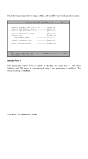
... Configuration menu: Onboard Devices Configuration Page 2/2 Onboard Floppy Disk Controller ......[Enabled] Onboard IDE Primary Channel .........[Enabled] Onboard IDE Secondary Channel .......[Enabled] Onboard PS/2 Mouse (IRQ 12) .........[Enabled] Onboard USB Disabled] USB Legacy Mode Onboard Ethernet Chip Enabled] SMBUS Interrupt(IRQ9 Disabled] ↑↓ = Move Highlight Bar, → ← = Change Setting, F1 = Help PgDn/PgUp = Move Screen Serial Port 1 This parameter allows you to enable or disable the serial port 1. The default setting is enabled. The Base Address...
... Configuration menu: Onboard Devices Configuration Page 2/2 Onboard Floppy Disk Controller ......[Enabled] Onboard IDE Primary Channel .........[Enabled] Onboard IDE Secondary Channel .......[Enabled] Onboard PS/2 Mouse (IRQ 12) .........[Enabled] Onboard USB Disabled] USB Legacy Mode Onboard Ethernet Chip Enabled] SMBUS Interrupt(IRQ9 Disabled] ↑↓ = Move Highlight Bar, → ← = Change Setting, F1 = Help PgDn/PgUp = Move Screen Serial Port 1 This parameter allows you to enable or disable the serial port 1. The default setting is enabled. The Base Address...

Acer Altos 1100 User's Guide
Page 74
... better. This setting depends on your application. This setting only affects the primary PCI components (PCI slots 1, 2, 3, 4, and onboard LAN). PCI IRQ Sharing Setting this parameter to set the length of the device currently using the PCI bus cannot go over the PCI latency time set to avoid conflicts. This parameter is grayed and not user-configurable when the PCI IRQ Setting is No. 2-32 Altos 1100 Series User's Guide To disable the feature...
... better. This setting depends on your application. This setting only affects the primary PCI components (PCI slots 1, 2, 3, 4, and onboard LAN). PCI IRQ Sharing Setting this parameter to set the length of the device currently using the PCI bus cannot go over the PCI latency time set to avoid conflicts. This parameter is grayed and not user-configurable when the PCI IRQ Setting is No. 2-32 Altos 1100 Series User's Guide To disable the feature...

Acer Altos 1100 User's Guide
Page 77
... memory whenever there is a write instruction. Selecting the option displays the following screen: Memory/Cache Configuration Page 1/1 Internal Cache (CPU Cache Enabled ] Cache Scheme Write Back] System BIOS Cacheable Enabled ] Video BIOS Cacheable Enabled ] Memory at 15MB-16MB Reserved for ....[ System ] Memory ECC Mode ECC ] Single Processor MP Table Enabled] ↑↓ = Move Highlight Bar, → ← = Change Setting, F1 = Help Internal Cache (CPU Cache) This parameter enables or disables the first-level or internal memory...
... memory whenever there is a write instruction. Selecting the option displays the following screen: Memory/Cache Configuration Page 1/1 Internal Cache (CPU Cache Enabled ] Cache Scheme Write Back] System BIOS Cacheable Enabled ] Video BIOS Cacheable Enabled ] Memory at 15MB-16MB Reserved for ....[ System ] Memory ECC Mode ECC ] Single Processor MP Table Enabled] ↑↓ = Move Highlight Bar, → ← = Change Setting, F1 = Help Internal Cache (CPU Cache) This parameter enables or disables the first-level or internal memory...

Acer Altos 1100 User's Guide
Page 80
xx% Event Logging Enabled] Clear Event Log Disabled] 8View Event Logs Event Control Temp/Vol/Fan Disabled] ECC Disabled] PCI Disabled] I/O Check Disabled] ↑↓ = Move Highlight Bar, → ← = Change Setting, F1 = Help System Event Logging Allows you to record monitored events that occurs in your system. The default setting is Enabled. 2-38 Altos 1100 Series User's Guide Selecting the option displays the following screen: System Event Configuration Page 1/2 System Event Logging Event Log BIOS Version 1.0 xxxxx Total Event Log Number xx Remain of Event Log ...
xx% Event Logging Enabled] Clear Event Log Disabled] 8View Event Logs Event Control Temp/Vol/Fan Disabled] ECC Disabled] PCI Disabled] I/O Check Disabled] ↑↓ = Move Highlight Bar, → ← = Change Setting, F1 = Help System Event Logging Allows you to record monitored events that occurs in your system. The default setting is Enabled. 2-38 Altos 1100 Series User's Guide Selecting the option displays the following screen: System Event Configuration Page 1/2 System Event Logging Event Log BIOS Version 1.0 xxxxx Total Event Log Number xx Remain of Event Log ...

Acer Altos 1100 User's Guide
Page 81
... or Error-Correcting Code tests the accuracy of this function. The default setting is Disabled. It can run at clock speeds of the system's temperature, volume, and CPU fan. This parameter monitors the activity of data as the Pentium. BIOS Utility 2-39 This parameter enables or disables the monitoring of memory. Chapter 2 - View Event Logs Opens the system event log file for new processors, such as it passes in status. The default setting is Disabled. Event Control This parameter monitors the following events and logs...
... or Error-Correcting Code tests the accuracy of this function. The default setting is Disabled. It can run at clock speeds of the system's temperature, volume, and CPU fan. This parameter monitors the activity of data as the Pentium. BIOS Utility 2-39 This parameter enables or disables the monitoring of memory. Chapter 2 - View Event Logs Opens the system event log file for new processors, such as it passes in status. The default setting is Disabled. Event Control This parameter monitors the following events and logs...

Acer Altos 1100 User's Guide
Page 110
...PCI system configuration, 2- 29 System event configuration, 2-36 ASM pro, 1-22 B BIOS release date, 2-9 BIOS utility, 2-1, 2-2 Abort settings change, 2-49 Advanced configuration, 2-21 Date and time, 2-44 Disk drives, 2-10 Entering setup, 2-1 Leaving setup, 2-49 Load setup default settings, 2-48 Power management, 2-16 Product information, 2-8 Remote diagnostic configuration, 2-46 Startup configuration, 2-18 System informatioin, 2-3 System security setup, 2-39 Boot from IDE CD-ROM, 2-20 Bus frequency, 2-5, 2-35 C Connector functions, 1-7 Correcting error conditions, 1-27 CPU speed configuration...
...PCI system configuration, 2- 29 System event configuration, 2-36 ASM pro, 1-22 B BIOS release date, 2-9 BIOS utility, 2-1, 2-2 Abort settings change, 2-49 Advanced configuration, 2-21 Date and time, 2-44 Disk drives, 2-10 Entering setup, 2-1 Leaving setup, 2-49 Load setup default settings, 2-48 Power management, 2-16 Product information, 2-8 Remote diagnostic configuration, 2-46 Startup configuration, 2-18 System informatioin, 2-3 System security setup, 2-39 Boot from IDE CD-ROM, 2-20 Bus frequency, 2-5, 2-35 C Connector functions, 1-7 Correcting error conditions, 1-27 CPU speed configuration...

Acer Altos 1100 User's Guide
Page 112
... USB, 2-7, 2-28 Opening the housing panels, 3-6 Front panel, 3-3, 3-6 Left panel, 3-7 P Parallel port, 2-7, 2-25 Base address, 2-24, 2-25 IRQ, 2-24, 2-25 PnP/PCI system configuration, 2-29 Graphics aperture size, 2-32 PCI device latency timer, 2-31 PCI IRQ settings, 2-30 PCI IRQ sharing, 2-31 Plug and play OS, 2-32 Reset resource assignments, 2-32 VGA palette snoop, 2-32 Pointing device, 2-7 Post-installation instructions, 1-12 Power management, 2-16 mode, 2-16 Power switch < 4 sec, 2-17 Wakeup event, 2-17 Power management mode, 2-16 IDE hard disk...
... USB, 2-7, 2-28 Opening the housing panels, 3-6 Front panel, 3-3, 3-6 Left panel, 3-7 P Parallel port, 2-7, 2-25 Base address, 2-24, 2-25 IRQ, 2-24, 2-25 PnP/PCI system configuration, 2-29 Graphics aperture size, 2-32 PCI device latency timer, 2-31 PCI IRQ settings, 2-30 PCI IRQ sharing, 2-31 Plug and play OS, 2-32 Reset resource assignments, 2-32 VGA palette snoop, 2-32 Pointing device, 2-7 Post-installation instructions, 1-12 Power management, 2-16 mode, 2-16 Power switch < 4 sec, 2-17 Wakeup event, 2-17 Power management mode, 2-16 IDE hard disk...
Acer Altos 1100 User's Guide
Page 113
... Setup password, 2-41 Bypassing, 2-43 Changing or removing, 2-42 Settting, 2-41 Silent boot, 2-19 Software error messages, 1-24 Standalone system, 3-2 Startup configuration, 2-18 4 Altos 1100 Series User's Guide Boot from IDE CD-ROM, 2-20 Fast POST mode, 2-18 Initialize SCSI before IDE, 2-19 Memory test, 2-19 Num lock after boot, 2-19 Silent boot, 2-19 System boot drive, 2-20 System BIOS ID, 2-9 System BIOS version, 2-9 System board, 1-1 ASM pro, 1-22 Error messages, 1-24 Features, 1-1 Front panel connectors, 1-9 Installing expansion cards, 1-20 Installing the termination board, 1-16 Jumpers...
... Setup password, 2-41 Bypassing, 2-43 Changing or removing, 2-42 Settting, 2-41 Silent boot, 2-19 Software error messages, 1-24 Standalone system, 3-2 Startup configuration, 2-18 4 Altos 1100 Series User's Guide Boot from IDE CD-ROM, 2-20 Fast POST mode, 2-18 Initialize SCSI before IDE, 2-19 Memory test, 2-19 Num lock after boot, 2-19 Silent boot, 2-19 System boot drive, 2-20 System BIOS ID, 2-9 System BIOS version, 2-9 System board, 1-1 ASM pro, 1-22 Error messages, 1-24 Features, 1-1 Front panel connectors, 1-9 Installing expansion cards, 1-20 Installing the termination board, 1-16 Jumpers...

Acer Altos 1100 User's Guide
Page 114
Disk drives, installing, 3-8 Expansion board, installing, 3-11 Features, 3-3 Hard disk drive cage, 3-13 Housing panels, opening, 3-6 Standalone system, 3-2 System information, 2-3 Bus frequency, 2-5, 2-35 External cache, 2-5 Floppy drive A, 2-5 Floppy drive B, 2-5 IDE primary channel master, 2-6 IDE primary channel slave, 2-6 IDE secondary channel master, 2-6 IDE secondary channel slave, 2-6 Internal cache, 2-5, 2-33 Memory parity mode, 2-7 Onboard USB, 2-7 Parallel port, 2-7, 2-25 Pointing device, 2-7 Processor, 2-4 Processor speed, 2-5, 2-35 Serial port 1, 2-7, 2-23 Serial port 2, 2-7, 2-24 ...
Disk drives, installing, 3-8 Expansion board, installing, 3-11 Features, 3-3 Hard disk drive cage, 3-13 Housing panels, opening, 3-6 Standalone system, 3-2 System information, 2-3 Bus frequency, 2-5, 2-35 External cache, 2-5 Floppy drive A, 2-5 Floppy drive B, 2-5 IDE primary channel master, 2-6 IDE primary channel slave, 2-6 IDE secondary channel master, 2-6 IDE secondary channel slave, 2-6 Internal cache, 2-5, 2-33 Memory parity mode, 2-7 Onboard USB, 2-7 Parallel port, 2-7, 2-25 Pointing device, 2-7 Processor, 2-4 Processor speed, 2-5, 2-35 Serial port 1, 2-7, 2-23 Serial port 2, 2-7, 2-24 ...


