

Acer Altos 1100 User's Guide
Page 9
1.14 Error Messages 1-24 1.14.1 Software Error Messages 1-24 1.14.2 System Error Messages 1-24 1.14.3 Correcting Error Conditions 1-27 Chapter 2 BIOS Utility 2.1 Entering Setup 2-1 2.2 System Information 2-3 2.2.1 Processor 2-4 2.2.2 Processor Speed 2-5 2.2.3 Bus Frequency 2-5 2.2.4 Internal Cache 2-5 2.2.5 External Cache 2-5 2.2.6 Floppy Drive A 2-5 2.2.7 Floppy Drive B 2-5 2.2.8 IDE Primary Channel Master 2-6 2.2.9 IDE Primary Channel ...
1.14 Error Messages 1-24 1.14.1 Software Error Messages 1-24 1.14.2 System Error Messages 1-24 1.14.3 Correcting Error Conditions 1-27 Chapter 2 BIOS Utility 2.1 Entering Setup 2-1 2.2 System Information 2-3 2.2.1 Processor 2-4 2.2.2 Processor Speed 2-5 2.2.3 Bus Frequency 2-5 2.2.4 Internal Cache 2-5 2.2.5 External Cache 2-5 2.2.6 Floppy Drive A 2-5 2.2.7 Floppy Drive B 2-5 2.2.8 IDE Primary Channel Master 2-6 2.2.9 IDE Primary Channel ...

Acer Altos 1100 User's Guide
Page 10
2.3.3 Main Board ID 2-9 2.3.4 Main Board S/N 2-9 2.3.5 System BIOS Version 2-9 2.3.6 System BIOS ID 2-9 2.3.7 BIOS Release Date 2-9 2.4 Disk Drives 2-10 2.4.1 Floppy Drives 2-12 2.4.2 IDE Drives 2-12 2.5 Power Management 2-16 2.5.1 Power Management Mode 2-16 2.5.2 Power Switch < 4 sec 2-17 2.5.3 Wakeup Event 2-17 2.6 ... Configuration 2-33 2.7.4 CPU Speed Configuration 2-35 2.7.5 System Event Configuration 2-36 2.8 System Security Setup 2-39 2.8.1 Disk Drive Control 2-40 2.8.2 Setup Password 2-41 2.8.3 Power-on Password 2-43 x Altos 1100 Series User's Guide
2.3.3 Main Board ID 2-9 2.3.4 Main Board S/N 2-9 2.3.5 System BIOS Version 2-9 2.3.6 System BIOS ID 2-9 2.3.7 BIOS Release Date 2-9 2.4 Disk Drives 2-10 2.4.1 Floppy Drives 2-12 2.4.2 IDE Drives 2-12 2.5 Power Management 2-16 2.5.1 Power Management Mode 2-16 2.5.2 Power Switch < 4 sec 2-17 2.5.3 Wakeup Event 2-17 2.6 ... Configuration 2-33 2.7.4 CPU Speed Configuration 2-35 2.7.5 System Event Configuration 2-36 2.8 System Security Setup 2-39 2.8.1 Disk Drive Control 2-40 2.8.2 Setup Password 2-41 2.8.3 Power-on Password 2-43 x Altos 1100 Series User's Guide

Acer Altos 1100 User's Guide
Page 13
... tells how to configure the system by setting the BIOS parameters. It also describes the IDM BPL3 wide SCSI backplane subsystem, which consists of error messages and corresponding corrective measures. At the end of... System Housing This chapter describes the features of three chapters. Chapter 1 System Board This chapter describes the system board and all its major components. Chapter 2 BIOS Utility This chapter gives information about the system board layout, jumper and connector locations, jumper settings, connector functions, and information on installing optional components. About...
... tells how to configure the system by setting the BIOS parameters. It also describes the IDM BPL3 wide SCSI backplane subsystem, which consists of error messages and corresponding corrective measures. At the end of... System Housing This chapter describes the features of three chapters. Chapter 1 System Board This chapter describes the system board and all its major components. Chapter 2 BIOS Utility This chapter gives information about the system board layout, jumper and connector locations, jumper settings, connector functions, and information on installing optional components. About...

Acer Altos 1100 User's Guide
Page 17
... system memory • Two ISA, four PCI, and one AGP bus slots (one PCI and ISA shared slot) • 512-KB Flash ROM for system BIOS • 512-KB pipelined-burst second-level cache built-in Pentium II CPU • System clock/calendar with battery backup • I/O APIC device that provides...
... system memory • Two ISA, four PCI, and one AGP bus slots (one PCI and ISA shared slot) • 512-KB Flash ROM for system BIOS • 512-KB pipelined-burst second-level cache built-in Pentium II CPU • System clock/calendar with battery backup • I/O APIC device that provides...
Acer Altos 1100 User's Guide
Page 20
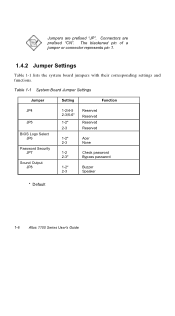
Connectors are prefixed "JP". The blackened pin of a jumper or connector represents pin 1. 1.4.2 Jumper Settings Table 1-1 lists the system board jumpers with their corresponding settings and functions. Jumpers are prefixed "CN". Table 1-1 System Board Jumper Settings Jumper Setting Function JP4 JP5 BIOS Logo Select JP6 Password Security JP7 Sound Output JP8 1-2/4-5 2-3/5-6* 1-2* 2-3 Reserved Reserved Reserved Reserved 1-2* Acer 2-3 None 1-2 Check password 2-3* Bypass password 1-2* Buzzer 2-3 Speaker * Default 1-6 Altos 1100 Series User's Guide
Connectors are prefixed "JP". The blackened pin of a jumper or connector represents pin 1. 1.4.2 Jumper Settings Table 1-1 lists the system board jumpers with their corresponding settings and functions. Jumpers are prefixed "CN". Table 1-1 System Board Jumper Settings Jumper Setting Function JP4 JP5 BIOS Logo Select JP6 Password Security JP7 Sound Output JP8 1-2/4-5 2-3/5-6* 1-2* 2-3 Reserved Reserved Reserved Reserved 1-2* Acer 2-3 None 1-2 Check password 2-3* Bypass password 1-2* Buzzer 2-3 Speaker * Default 1-6 Altos 1100 Series User's Guide

Acer Altos 1100 User's Guide
Page 34
When you turn on the system board. 2. Figure 1-11 Installing a PCI Card 1-20 Altos 1100 Series User's Guide Locate the PCI slots on the system, BIOS automatically detects and assigns resources to the housing with a screw. Secure the card to the PCI devices. Insert a PCI card into the slot. Remove the bracket on the housing opposite an empty PCI slot. 3. 1.11 Installing Expansion Cards 1.11.1 Installing 32 Bit PCI Cards To install 32 bit PCI cards: 1. Make sure that the card is properly seated. 4.
When you turn on the system board. 2. Figure 1-11 Installing a PCI Card 1-20 Altos 1100 Series User's Guide Locate the PCI slots on the system, BIOS automatically detects and assigns resources to the housing with a screw. Secure the card to the PCI devices. Insert a PCI card into the slot. Remove the bracket on the housing opposite an empty PCI slot. 3. 1.11 Installing Expansion Cards 1.11.1 Installing 32 Bit PCI Cards To install 32 bit PCI cards: 1. Make sure that the card is properly seated. 4.

Acer Altos 1100 User's Guide
Page 35
... Card When installing an AGP card, make sure that the card is not already assigned to a PCI or ISA device to the AGP device. Chapter 1 - BIOS detects and configures only PnP cards. See Figure 1-1 for the slot location. 2. Follow these steps when installing an AGP card: 1. Figure 1-12 Installing an AGP... Card When you turn on the main board. Insert an AGP card into the slot. System Board 1-21 Locate the AGP slot on the system, BIOS automatically detects and assigns resources to avoid resource conflicts. Make sure that the IRQ required by the card is properly seated.
... Card When installing an AGP card, make sure that the card is not already assigned to a PCI or ISA device to the AGP device. Chapter 1 - BIOS detects and configures only PnP cards. See Figure 1-1 for the slot location. 2. Follow these steps when installing an AGP card: 1. Figure 1-12 Installing an AGP... Card When you turn on the main board. Insert an AGP card into the slot. System Board 1-21 Locate the AGP slot on the system, BIOS automatically detects and assigns resources to avoid resource conflicts. Make sure that the IRQ required by the card is properly seated.

Acer Altos 1100 User's Guide
Page 37
In the event of failure, RDM monitors and analyzes the server condition, updates the BIOS settings if necessary, reboots the server, and quickly returns it into CN30 and CN33. Do not force it to re-install the RDM module and ...
In the event of failure, RDM monitors and analyzes the server condition, updates the BIOS settings if necessary, reboots the server, and quickly returns it into CN30 and CN33. Do not force it to re-install the RDM module and ...
Acer Altos 1100 User's Guide
Page 40
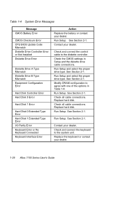
.... Check and connect the keyboard to the diskette controller. Table 1-4 System Error Messages Message CMOS Battery Error CMOS Checksum Error CPU BIOS Update Code Mismatch Diskette Drive Controller Error or Not Installed Diskette Drive Error Diskette Drive A Type Mismatch Diskette Drive B Type Mismatch ...Parity Error Keyboard Error or No Keyboard Connected Keyboard Interface Error Action Replace the battery or contact your dealer. 1-26 Altos 1100 Series User's Guide Run Setup. Check the CMOS settings in Table 1-4. Run Setup. Replace the keyboard or contact your dealer.
.... Check and connect the keyboard to the diskette controller. Table 1-4 System Error Messages Message CMOS Battery Error CMOS Checksum Error CPU BIOS Update Code Mismatch Diskette Drive Controller Error or Not Installed Diskette Drive Error Diskette Drive A Type Mismatch Diskette Drive B Type Mismatch ...Parity Error Keyboard Error or No Keyboard Connected Keyboard Interface Error Action Replace the battery or contact your dealer. 1-26 Altos 1100 Series User's Guide Run Setup. Check the CMOS settings in Table 1-4. Run Setup. Replace the keyboard or contact your dealer.

Acer Altos 1100 User's Guide
Page 43
Ask a qualified technician for assistance. 2.1 Entering Setup To enter Setup, press the key combination ++. The BIOS Utility main menu then appears: Chapter 2 - There is booting. If you get a Run Setup message. This key combination does not work during any other time. ... the system is no need to run Setup when starting the computer unless you repeatedly receive Run Setup messages, the battery may be bad. BIOS Utility 2-1 Chapter 2 BIOS Utility Most systems are already configured by the manufacturer or the dealer. This memory area is not part of the system RAM. In this...
Ask a qualified technician for assistance. 2.1 Entering Setup To enter Setup, press the key combination ++. The BIOS Utility main menu then appears: Chapter 2 - There is booting. If you get a Run Setup message. This key combination does not work during any other time. ... the system is no need to run Setup when starting the computer unless you repeatedly receive Run Setup messages, the battery may be bad. BIOS Utility 2-1 Chapter 2 BIOS Utility Most systems are already configured by the manufacturer or the dealer. This memory area is not part of the system RAM. In this...

Acer Altos 1100 User's Guide
Page 44
These values may not be the same as those in your system. 2-2 Altos 1100 Series User's Guide BIOS Utility System Information Product Information Disk Drives Power Management Startup Configuration Advanced Configuration System Security Date and Time Remote Diagnostic Configuration Load Default Settings Abort Settings Change Move highlight bar, ↵ = Select, Esc = Exit The parameters on the screens show default values.
These values may not be the same as those in your system. 2-2 Altos 1100 Series User's Guide BIOS Utility System Information Product Information Disk Drives Power Management Startup Configuration Advanced Configuration System Security Date and Time Remote Diagnostic Configuration Load Default Settings Abort Settings Change Move highlight bar, ↵ = Select, Esc = Exit The parameters on the screens show default values.

Acer Altos 1100 User's Guide
Page 45
Press to move from the main menu. BIOS Utility 2-3 2.2 System Information The following screen appears if you how to the main menu. System Information Page 1/2 Processor Pentium II Processor Speed xxx MHz Bus ...
Press to move from the main menu. BIOS Utility 2-3 2.2 System Information The following screen appears if you how to the main menu. System Information Page 1/2 Processor Pentium II Processor Speed xxx MHz Bus ...
Acer Altos 1100 User's Guide
Page 46
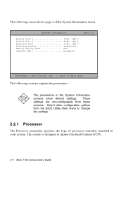
These settings are non-configurable from the BIOS Utility main menu to support the Intel Pentium II CPU. 2-4 Altos 1100 Series User's Guide The parameters in your system. Select other configuration options from these screens. System Information Page 2/2 Serial Port 1 3F8h, IRQ 4 Serial Port 2 2F8h, ...
These settings are non-configurable from the BIOS Utility main menu to support the Intel Pentium II CPU. 2-4 Altos 1100 Series User's Guide The parameters in your system. Select other configuration options from these screens. System Information Page 2/2 Serial Port 1 3F8h, IRQ 4 Serial Port 2 2F8h, ...

Acer Altos 1100 User's Guide
Page 47
..., see section 2.7.3. 2.2.5 External Cache This parameter specifies the second-level cache memory size currently supported by the system, and whether it is enabled or disabled. BIOS Utility 2-5 The system supports Intel Pentium II CPUs running at 400 or 450 MHz. 2.2.3 Bus Frequency The Bus Frequency parameter specifies the system external clock...
..., see section 2.7.3. 2.2.5 External Cache This parameter specifies the second-level cache memory size currently supported by the system, and whether it is enabled or disabled. BIOS Utility 2-5 The system supports Intel Pentium II CPUs running at 400 or 450 MHz. 2.2.3 Bus Frequency The Bus Frequency parameter specifies the system external clock...
Acer Altos 1100 User's Guide
Page 48
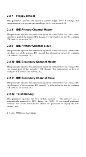
... configuration of the IDE device connected to the master port of the secondary IDE channel. The memory size is automatically detected by BIOS during the POST. If you install additional memory, the system automatically adjusts this parameter to the slave port of the primary IDE...specifies the current configuration of the IDE device connected to the slave port of the IDE device connected to display the new memory size. 2-6 Altos 1100 Series User's Guide 2.2.7 Floppy Drive B This parameter specifies the system's current floppy drive B settings. For information on how to configure the...
... configuration of the IDE device connected to the master port of the secondary IDE channel. The memory size is automatically detected by BIOS during the POST. If you install additional memory, the system automatically adjusts this parameter to the slave port of the primary IDE...specifies the current configuration of the IDE device connected to the slave port of the IDE device connected to display the new memory size. 2-6 Altos 1100 Series User's Guide 2.2.7 Floppy Drive B This parameter specifies the system's current floppy drive B settings. For information on how to configure the...

Acer Altos 1100 User's Guide
Page 49
... indicates the serial port 2 address and IRQ setting. 2.2.15 Parallel Port This parameter indicates the parallel port address and IRQ setting. 2.2.16 Pointing Device The BIOS utility automatically detects if there is ECC. Memory Type This parameter indicates the type of the memory parity mode. Otherwise, this parameter displays the Installed...
... indicates the serial port 2 address and IRQ setting. 2.2.15 Parallel Port This parameter indicates the parallel port address and IRQ setting. 2.2.16 Pointing Device The BIOS utility automatically detects if there is ECC. Memory Type This parameter indicates the type of the memory parity mode. Otherwise, this parameter displays the Installed...

Acer Altos 1100 User's Guide
Page 51
... the Product Information items. Product Information Page 1/1 Product Name M19A System S/N xxxxxxxxx Main Board ID M19A Main Board S/N xxxxxxxxx System BIOS Version vx.xx System BIOS ID xxx.xx xxx-xx BIOS Release Date xx/xx/xx Esc = Back to Main Menu 2.3.1 Product Name This parameter specifies the official name of the system...
... the Product Information items. Product Information Page 1/1 Product Name M19A System S/N xxxxxxxxx Main Board ID M19A Main Board S/N xxxxxxxxx System BIOS Version vx.xx System BIOS ID xxx.xx xxx-xx BIOS Release Date xx/xx/xx Esc = Back to Main Menu 2.3.1 Product Name This parameter specifies the official name of the system...

Acer Altos 1100 User's Guide
Page 52
2.3.3 Main Board ID This parameter specifies the system board's identification number. 2.3.4 Main Board S/N This parameter specifies the system board's serial number. 2.3.5 System BIOS Version This parameter specifies the version of the BIOS utility. 2.3.6 System BIOS ID This parameter specifies the identification number of the BIOS utility. 2.3.7 BIOS Release Date This parameter specifies the official date the BIOS version was released. 2-10 Altos 1100 Series User's Guide
2.3.3 Main Board ID This parameter specifies the system board's identification number. 2.3.4 Main Board S/N This parameter specifies the system board's serial number. 2.3.5 System BIOS Version This parameter specifies the version of the BIOS utility. 2.3.6 System BIOS ID This parameter specifies the identification number of the BIOS utility. 2.3.7 BIOS Release Date This parameter specifies the official date the BIOS version was released. 2-10 Altos 1100 Series User's Guide

Acer Altos 1100 User's Guide
Page 53
Select the item to display the menu. Chapter 2 - BIOS Utility 2-11 If your hard disk supports the enhanced IDE features, you configure the system hard disk and disk drive settings. 2.4 Disk Drives The Disk ...
Select the item to display the menu. Chapter 2 - BIOS Utility 2-11 If your hard disk supports the enhanced IDE features, you configure the system hard disk and disk drive settings. 2.4 Disk Drives The Disk ...

Acer Altos 1100 User's Guide
Page 55
BIOS Utility 2-13 Select the IDE Primary Channel Chapter 2 - Choose None if you want to configure an IDE device set as master. There are neither qualified ... item (or the IDE Secondary Channel Master) if you do not have a second floppy drive. 2.4.2 IDE Drives Although IDE options are provided in the system BIOS, IDE hard disk drives are four IDE drive option items under the Disk Drives menu. Possible settings for the Floppy Drive parameters: • [ None ] •...
BIOS Utility 2-13 Select the IDE Primary Channel Chapter 2 - Choose None if you want to configure an IDE device set as master. There are neither qualified ... item (or the IDE Secondary Channel Master) if you do not have a second floppy drive. 2.4.2 IDE Drives Although IDE options are provided in the system BIOS, IDE hard disk drives are four IDE drive option items under the Disk Drives menu. Possible settings for the Floppy Drive parameters: • [ None ] •...


