
User Manual
Page 15
...Power-on problems 23 Configuring the system OS 24 Turning off the system 25 3 System upgrades 27 Installation precautions 28 ESD precautions 28 Pre-installation instructions 28 Post-installation instructions 29 Configuring the hard disk drive 30 Accessing the drive bays 30 Guidelines for configuring hard disk drives 30 Determining the drive status 31 Installing and removing a hard disk drive 32 Installing an additional hard disk drive with carrier 34 Opening the server 36 Removing and installing the side panel 36 Configuring a 5.25" storage device 38 Replacing...
...Power-on problems 23 Configuring the system OS 24 Turning off the system 25 3 System upgrades 27 Installation precautions 28 ESD precautions 28 Pre-installation instructions 28 Post-installation instructions 29 Configuring the hard disk drive 30 Accessing the drive bays 30 Guidelines for configuring hard disk drives 30 Determining the drive status 31 Installing and removing a hard disk drive 32 Installing an additional hard disk drive with carrier 34 Opening the server 36 Removing and installing the side panel 36 Configuring a 5.25" storage device 38 Replacing...
User Manual
Page 16
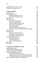
...Configuration 76 Power menu 78 Security menu 80 Setting a system password 82 Changing a system password 82 Removing a system password 82 Server Management menu 83 System Information 84 Console Redirection 85 Event Log Configuration 86 Boot menu 88 Exit menu 89 5 System troubleshooting 91 Resetting the system 92 Initial system startup problems 93 Initial troubleshooting checklist 94 Hardware diagnostic testing 95 Checking the boot-up status 95 Verifying the condition of the storage devices 96 Confirming loading of the operating system 96 Specific problems...
...Configuration 76 Power menu 78 Security menu 80 Setting a system password 82 Changing a system password 82 Removing a system password 82 Server Management menu 83 System Information 84 Console Redirection 85 Event Log Configuration 86 Boot menu 88 Exit menu 89 5 System troubleshooting 91 Resetting the system 92 Initial system startup problems 93 Initial troubleshooting checklist 94 Hardware diagnostic testing 95 Checking the boot-up status 95 Verifying the condition of the storage devices 96 Confirming loading of the operating system 96 Specific problems...

User Manual
Page 17
...Appendix B Rack mount configuration Rack installation information System rack installation Vertical mounting hole pattern Installing the system into the rack Appendix C Acer Smart Console Using Acer Smart Console Software Installation Prerequisites on remote management PC Installing the Java Tool Installing the UPnP tool Using the UPnP tool to search for a server Configuring the BMC NIC settings Accessing Acer Smart Console Acer Smart Console user interface System status indicator System Information Server Health Configuration Remote Control Maintenance KVM Remote Console Utility Menu bar 101...
...Appendix B Rack mount configuration Rack installation information System rack installation Vertical mounting hole pattern Installing the system into the rack Appendix C Acer Smart Console Using Acer Smart Console Software Installation Prerequisites on remote management PC Installing the Java Tool Installing the UPnP tool Using the UPnP tool to search for a server Configuring the BMC NIC settings Accessing Acer Smart Console Acer Smart Console user interface System status indicator System Information Server Health Configuration Remote Control Maintenance KVM Remote Console Utility Menu bar 101...

User Manual
Page 20
... DDR31333 DIMM slots that support both tower and rack-mount configurations. The server accepts up in both Unbufferred ECC and Registered DIMMs, four PCI-E slots and one 32-bit/33 MHz PCI slot, onboard SATA SW RAID with RAID 0, 1, 5 or 10 support, onboard Baseboard Management Controller (BMC), iKVM feature, and an integrated VGA with 32 MB memory. The server board is a single-processor tower server designed to three optical devices and four hot-pluggable SATA/SAS hard disk drives, configurable for easy hardware access and set...
... DDR31333 DIMM slots that support both tower and rack-mount configurations. The server accepts up in both Unbufferred ECC and Registered DIMMs, four PCI-E slots and one 32-bit/33 MHz PCI slot, onboard SATA SW RAID with RAID 0, 1, 5 or 10 support, onboard Baseboard Management Controller (BMC), iKVM feature, and an integrated VGA with 32 MB memory. The server board is a single-processor tower server designed to three optical devices and four hot-pluggable SATA/SAS hard disk drives, configurable for easy hardware access and set...

User Manual
Page 29
... 13 FAN3 14 IPMB 15 16 NMI_BTN 17 BPB_SMBUS 18 U2 19 SATA0-3 11 Description Serial port (top) VGA port (bottom) LAN1 port (top) USB ports (bottom) LAN2 port (top) USB ports (bottom) Server management port System ID button 8-pin ATX power connector 24-pin ATX power connector Power supply PSMI connector DDR3 DIMM slots Processor socket Battery System fan 3 cable connector IPMB header (for an IPMI card) Select jumpers NMI button Backplane board system management bus (SMBUS) connector Intel 3420 PCH chipset Mini-SAS port (supports 4 ports, SATA only) No.
... 13 FAN3 14 IPMB 15 16 NMI_BTN 17 BPB_SMBUS 18 U2 19 SATA0-3 11 Description Serial port (top) VGA port (bottom) LAN1 port (top) USB ports (bottom) LAN2 port (top) USB ports (bottom) Server management port System ID button 8-pin ATX power connector 24-pin ATX power connector Power supply PSMI connector DDR3 DIMM slots Processor socket Battery System fan 3 cable connector IPMB header (for an IPMI card) Select jumpers NMI button Backplane board system management bus (SMBUS) connector Intel 3420 PCH chipset Mini-SAS port (supports 4 ports, SATA only) No.

User Manual
Page 30
Code 20 SATA4 21 SATA5 22 CASE_OPEN 23 CLR_CMOS1 24 USB1 25 USB2 26 F_PANEL 27 COM2 28 PCI5 29 PCI4 30 PCI3 31 PCI2 32 U28 33 PCI1 34 FAN2 35 FAN4 1 System tour Description SATA 4 port SATA 5 port Chassis intrusion header Clear CMOS jumper Front USB1 cable connector Internal USB connector Front panel connector Connects to serial port PCI slot (32-bit/33 MHz, 3.3 V) PCI-E x8 slot (x4 signal) PCI-E x16 slot (x8 signal) PCI-E x4 slot (x1 signal) BMC controller PCI-E x8 slot (x8 signal) System fan 2 cable connector Connects to the rear system fan System fan 4 cable connector 12 No.
Code 20 SATA4 21 SATA5 22 CASE_OPEN 23 CLR_CMOS1 24 USB1 25 USB2 26 F_PANEL 27 COM2 28 PCI5 29 PCI4 30 PCI3 31 PCI2 32 U28 33 PCI1 34 FAN2 35 FAN4 1 System tour Description SATA 4 port SATA 5 port Chassis intrusion header Clear CMOS jumper Front USB1 cable connector Internal USB connector Front panel connector Connects to serial port PCI slot (32-bit/33 MHz, 3.3 V) PCI-E x8 slot (x4 signal) PCI-E x16 slot (x8 signal) PCI-E x4 slot (x1 signal) BMC controller PCI-E x8 slot (x8 signal) System fan 2 cable connector Connects to the rear system fan System fan 4 cable connector 12 No.

User Manual
Page 69
... Installing a memory module Warning! Reverse the orientation of memory installed. Memory of the identical size, speed, and organization must be installed in the slot, you insert an DIMM but it . The system automatically detects the amount of the module and insert it again. (2) Firmly press the holding clips do not close, the DIMM is not properly inserted. 5 Observe the post-installation instructions described on the slot fits the keyed edge...
... Installing a memory module Warning! Reverse the orientation of memory installed. Memory of the identical size, speed, and organization must be installed in the slot, you insert an DIMM but it . The system automatically detects the amount of the module and insert it again. (2) Firmly press the holding clips do not close, the DIMM is not properly inserted. 5 Observe the post-installation instructions described on the slot fits the keyed edge...

User Manual
Page 79
61 Main menu Parameter Description Option System BIOS Version Build Date Version number of extended memory detected during POST. Quiet Boot Allows the bootup screen options to display the POST messages. Enabled Disabled Date when the BIOS Setup Utility was created. Processor CPU Type Core Frequency Count Technical specifications for the installed processor. Select Disabled to be modified between POST messages or the OEM logo. Memory Size Total size of the BIOS Setup Utility. Select Enabled to display the OEM logo instead of the normal POST messages.
61 Main menu Parameter Description Option System BIOS Version Build Date Version number of extended memory detected during POST. Quiet Boot Allows the bootup screen options to display the POST messages. Enabled Disabled Date when the BIOS Setup Utility was created. Processor CPU Type Core Frequency Count Technical specifications for the installed processor. Select Disabled to be modified between POST messages or the OEM logo. Memory Size Total size of the BIOS Setup Utility. Select Enabled to display the OEM logo instead of the normal POST messages.

User Manual
Page 83
.... Options Enabled Disabled Enabled Disabled Enabled Disabled One Core Two cores Max Core Enabled Disabled Enabled Disabled When enabled, the CPU core frequency and voltage will run multiple operating systems and applications in independent partitions, creating multiple virtual systems in data-only memory pages. Select whether to processor load. Sets the active processor core. If enabled, all logical processors in a physical processor will be reduced when the CPU is displayed. Enables or disables Intel CPU Thermal Monitor function, a CPU overheating protection...
.... Options Enabled Disabled Enabled Disabled Enabled Disabled One Core Two cores Max Core Enabled Disabled Enabled Disabled When enabled, the CPU core frequency and voltage will run multiple operating systems and applications in independent partitions, creating multiple virtual systems in data-only memory pages. Select whether to processor load. Sets the active processor core. If enabled, all logical processors in a physical processor will be reduced when the CPU is displayed. Enables or disables Intel CPU Thermal Monitor function, a CPU overheating protection...

User Manual
Page 88
... access to the RAID setup utility. When set to AHCI, the SATA controller enables its RAID and AHCI functions and runs in place of sectors per block for multiple sector transfers. Enabled Disabled Enabled Disabled Enables/disables 32-bit IDE data transfers. You will not be used in the IDE emulation mode. You are allowed to access the RAID setup utility at boot time. 70 Parameter SATA Mode Selection SATA Port 0/1/2/3/4/5 Type Multisector Transfer LBA Mode Control 32-bit I/O 4 System BIOS Description Options When set...
... access to the RAID setup utility. When set to AHCI, the SATA controller enables its RAID and AHCI functions and runs in place of sectors per block for multiple sector transfers. Enabled Disabled Enabled Disabled Enables/disables 32-bit IDE data transfers. You will not be used in the IDE emulation mode. You are allowed to access the RAID setup utility at boot time. 70 Parameter SATA Mode Selection SATA Port 0/1/2/3/4/5 Type Multisector Transfer LBA Mode Control 32-bit I/O 4 System BIOS Description Options When set...

User Manual
Page 111
If the problem you are usually caused by an incorrect installation or configuration. Hardware failure is problem with the software program" section on page 99. 93 Initial system startup problems Problems that occur at initial system startup are experiencing is with a specific application, see the "There is a less possible cause.
If the problem you are usually caused by an incorrect installation or configuration. Hardware failure is problem with the software program" section on page 99. 93 Initial system startup problems Problems that occur at initial system startup are experiencing is with a specific application, see the "There is a less possible cause.

User Manual
Page 112
... device drivers properly installed? • Are hard disk drive(s) properly formatted and configured? • Are the BIOS configuration settings in the BIOS Setup Utility correct? • Is the operating system properly loaded? and connected to the manufacturer's documentation that there are encountering. • AC power is available at the wall outlet? • Is the power supply module properly installed? • Is the system power cord properly plugged into the power supply module socket? To check these settings...
... device drivers properly installed? • Are hard disk drive(s) properly formatted and configured? • Are the BIOS configuration settings in the BIOS Setup Utility correct? • Is the operating system properly loaded? and connected to the manufacturer's documentation that there are encountering. • AC power is available at the wall outlet? • Is the power supply module properly installed? • Is the system power cord properly plugged into the power supply module socket? To check these settings...

User Manual
Page 115
... processors, and that may arise during the use of your server and their possible solutions. 97 Specific problems and corrective actions Listed below are specific problems that they are populated according to the system guidelines. Power indicator does not light. If reboot is connected correctly. • Make sure that relevant switches and jumpers on the hard drive and on the front panel is lit up. • Remove all add...
... processors, and that may arise during the use of your server and their possible solutions. 97 Specific problems and corrective actions Listed below are specific problems that they are populated according to the system guidelines. Power indicator does not light. If reboot is connected correctly. • Make sure that relevant switches and jumpers on the hard drive and on the front panel is lit up. • Remove all add...

User Manual
Page 116
... SATA and power cables are properly connected. • Check that relevant switches and jumpers on the switch. 98 5 System troubleshooting Optical drive activity indicator does not light. Insert the tip of disc. • Make sure the disc is properly seated in proper condition. • Reinstall the network drivers. • Try another port or hub on the drive are not detected. Do the following : • Check the cabling and network...
... SATA and power cables are properly connected. • Check that relevant switches and jumpers on the switch. 98 5 System troubleshooting Optical drive activity indicator does not light. Insert the tip of disc. • Make sure the disc is properly seated in proper condition. • Reinstall the network drivers. • Try another port or hub on the drive are not detected. Do the following : • Check the cabling and network...

User Manual
Page 117
... the display monitor plugged in and turned on the video monitor properly adjusted? • Is the display monitor signal cable properly connected? • Does this display monitor work . There is properly configured for instructions on the display monitor. Do the following : • Verify that came with the software program. Do the following : • Make sure the correct network drivers are using a switch box, is causing the problem. If reboot is successful, install the cards...
... the display monitor plugged in and turned on the video monitor properly adjusted? • Is the display monitor signal cable properly connected? • Does this display monitor work . There is properly configured for instructions on the display monitor. Do the following : • Verify that came with the software program. Do the following : • Make sure the correct network drivers are using a switch box, is causing the problem. If reboot is successful, install the cards...

User Manual
Page 121
... shows the adapter settings. The indicator for the selected drive changes from Objects. Creating RAID Volume 1 Select Configuration from the Management Menu. 2 Select New Configuration from this menu. 4 Select Factory Default and Yes to load the default settings. 5 Exit the configuration utility and press + + to reboot the server. You can change the settings from the Configuration menu. An array selection window displays the devices connected to the current controller. 3 Press the arrow keys to choose specific physical drives and press...
... shows the adapter settings. The indicator for the selected drive changes from Objects. Creating RAID Volume 1 Select Configuration from the Management Menu. 2 Select New Configuration from this menu. 4 Select Factory Default and Yes to load the default settings. 5 Exit the configuration utility and press + + to reboot the server. You can change the settings from the Configuration menu. An array selection window displays the devices connected to the current controller. 3 Press the arrow keys to choose specific physical drives and press...

User Manual
Page 162
... BMC commands are allowed, except for disabling a communication channel. The BMC (Baseboard Management Controller) maintains a local database of -band interfaces. Operator privilege can configure the software and add users. The administrator privilege has full access and can not disable individual channels or change the behavior of the out-of remote access users and their privileges. Users can assign to the system. The operator privilege has restricted access. The table below lists the...
... BMC commands are allowed, except for disabling a communication channel. The BMC (Baseboard Management Controller) maintains a local database of -band interfaces. Operator privilege can configure the software and add users. The administrator privilege has full access and can not disable individual channels or change the behavior of the out-of remote access users and their privileges. Users can assign to the system. The operator privilege has restricted access. The table below lists the...

User Manual
Page 173
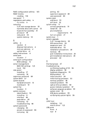
... inch device bays location 3 5.25 inch storage device installing 38 removing 39 A Acer Smart Console 120 accessing 127 BMC NIC settings 125 Configuration 135 installing 121 Maintenance 149 Remote Control 147 Server Health 132 System Information 130 system status alert indicator 129 UPnP tool 122 user interface 129 Acer Smart Setup scope 24 using 24 Adaptec onboard SATA RAID controller enabling 105 Adaptec onboard SATA RAID Configuration Utility entering 105 additional hard disk drive installing 34 ATA controller configuration BIOS settings 69 B backplane board jumper settings 14 BIOS CMOS RAM...
... inch device bays location 3 5.25 inch storage device installing 38 removing 39 A Acer Smart Console 120 accessing 127 BMC NIC settings 125 Configuration 135 installing 121 Maintenance 149 Remote Control 147 Server Health 132 System Information 130 system status alert indicator 129 UPnP tool 122 user interface 129 Acer Smart Setup scope 24 using 24 Adaptec onboard SATA RAID controller enabling 105 Adaptec onboard SATA RAID Configuration Utility entering 105 additional hard disk drive installing 34 ATA controller configuration BIOS settings 69 B backplane board jumper settings 14 BIOS CMOS RAM...

User Manual
Page 174
... storage device 38 additional hard disk drive 34 cable arm 117 expansion card 53 hard disk drive with carrier 32 heatsink fan assembly 43 processor 46 rack 112 side panel 37 system memory 51 internal components 9 K KVM Remote Console 151 L LAN ports location 8 troubleshooting 98 LED indicators front panel 5 LAN port 8 M mainboard jumper settings 13 memory configuration BIOS settings 68 monitor port 7 O opening the server installing side panel 36 removing side panel 36 operating system configure 24 optical drive location 3 troubleshooting 98 P PCI bus slots overview 53 PCI configuration BIOS...
... storage device 38 additional hard disk drive 34 cable arm 117 expansion card 53 hard disk drive with carrier 32 heatsink fan assembly 43 processor 46 rack 112 side panel 37 system memory 51 internal components 9 K KVM Remote Console 151 L LAN ports location 8 troubleshooting 98 LED indicators front panel 5 LAN port 8 M mainboard jumper settings 13 memory configuration BIOS settings 68 monitor port 7 O opening the server installing side panel 36 removing side panel 36 operating system configure 24 optical drive location 3 troubleshooting 98 P PCI bus slots overview 53 PCI configuration BIOS...
User Manual
Page 175
RAID configuration utilities 103 RAID Volume creating 105 rear panel 7 regulations and safety ix fcc notice ix removing 5.25 inch storage device 39 hard disk drive with carrier 33 heatsink fan assembly 41 processor 44 side panel 36 system memory 52 S safety iii caution iii disposal instructions vi mercury advisory vi optical drive xii safety instructions iii serial port location 7 serial port configuration BIOS settings 72 server management BMC NIC settings 125 tools 102 side panel installing 37 removing 36 supervisor password 80 system BIOS 57 system boards backplane board 14...
RAID configuration utilities 103 RAID Volume creating 105 rear panel 7 regulations and safety ix fcc notice ix removing 5.25 inch storage device 39 hard disk drive with carrier 33 heatsink fan assembly 41 processor 44 side panel 36 system memory 52 S safety iii caution iii disposal instructions vi mercury advisory vi optical drive xii safety instructions iii serial port location 7 serial port configuration BIOS settings 72 server management BMC NIC settings 125 tools 102 side panel installing 37 removing 36 supervisor password 80 system BIOS 57 system boards backplane board 14...


