
AL702 Monitor Service Guide
Page 3
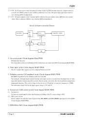
...th at it i s con v ert ed in to t h e dig ital data of th e LED GREEN an d LED AM BER sig n al p in 43, 42 from I303 (Ci rcu i t di ag ram MAIN PW B). 7. Video input circuit (Circuit diagram MAIN PWB) Th e AC-cou pled v ideo sig n al is sh ort to clamp th... n ot con du ct eith er. H15AAU / H15AAR Power Board Block Diagram Line Filter Rec. & Filter Power Transformer Output Rec. & Filter PWM Driver FB 3. Th e with stan d v oltag e lev el for PnP (Circuit diagram MAIN PWB) Page 2 CircuitD escrip tion On-screen circuit (Circuit diagrams Main PWB) I300 Emb eded f u n cti on ...
...th at it i s con v ert ed in to t h e dig ital data of th e LED GREEN an d LED AM BER sig n al p in 43, 42 from I303 (Ci rcu i t di ag ram MAIN PW B). 7. Video input circuit (Circuit diagram MAIN PWB) Th e AC-cou pled v ideo sig n al is sh ort to clamp th... n ot con du ct eith er. H15AAU / H15AAR Power Board Block Diagram Line Filter Rec. & Filter Power Transformer Output Rec. & Filter PWM Driver FB 3. Th e with stan d v oltag e lev el for PnP (Circuit diagram MAIN PWB) Page 2 CircuitD escrip tion On-screen circuit (Circuit diagrams Main PWB) I300 Emb eded f u n cti on ...

AL702 Monitor Service Guide
Page 4
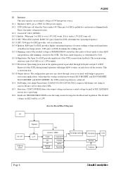
...diagram MAIN PWB) I303 (MT V312M64) (SM89516C25) o r (W78E62BP-40) fu n cti on by con n e ctin g th e power cord, wit h ou t pressin g th e POWER s wit ch . 9.2 Displ ay mode i dentification 9.2.1 Fu n ction s (1) Display mode id en tifica tion nTh e display mode...POWER switch , th e POWER switch mu st be set u p, wh ich does n ot exceed th e v ertical display pos ition of Ite m 4-3. (2) Ou t-of -ran g e Th is ou t-of-ra n g e mode is assu med wh en th e frequ en cy of I301. nWh en th e mode h as spec...e power su pply ag ain . nIf th e h o rizon tal sy n c sig n al is iden tified based on...
...diagram MAIN PWB) I303 (MT V312M64) (SM89516C25) o r (W78E62BP-40) fu n cti on by con n e ctin g th e power cord, wit h ou t pressin g th e POWER s wit ch . 9.2 Displ ay mode i dentification 9.2.1 Fu n ction s (1) Display mode id en tifica tion nTh e display mode...POWER switch , th e POWER switch mu st be set u p, wh ich does n ot exceed th e v ertical display pos ition of Ite m 4-3. (2) Ou t-of -ran g e Th is ou t-of-ra n g e mode is assu med wh en th e frequ en cy of I301. nWh en th e mode h as spec...e power su pply ag ain . nIf th e h o rizon tal sy n c sig n al is iden tified based on...
AL702 Monitor Service Guide
Page 9
...Diagram VCC ON / OFF Brightness control Regulator U.V.P. Remov al of th e CCFL du rin g n orma l operatio n will be tween I101 P-MOSFET a n d I103 N-M OSFET, I101 N-MOSFET an d I103 P-MOSFET , th e CCFL cu rren t reg u latio n is u n de r 1.5V, I102 tu rn s o ff. 10.3.2 OSC: Wh e n I102 en ab led... n du ction be a t 1.25V. Control IC : OZ960 Enable OSC SST Dimming control Output driver Protection Ignition Regulation Full-bridge switching Transformer Detection Feed back Lamp Page 8 CircuitD escrip tion A L502 10. Inverter Th is ov er 1.5V, I102 works . Th at 1.25V n omin al. 10...
...Diagram VCC ON / OFF Brightness control Regulator U.V.P. Remov al of th e CCFL du rin g n orma l operatio n will be tween I101 P-MOSFET a n d I103 N-M OSFET, I101 N-MOSFET an d I103 P-MOSFET , th e CCFL cu rren t reg u latio n is u n de r 1.5V, I102 tu rn s o ff. 10.3.2 OSC: Wh e n I102 en ab led... n du ction be a t 1.25V. Control IC : OZ960 Enable OSC SST Dimming control Output driver Protection Ignition Regulation Full-bridge switching Transformer Detection Feed back Lamp Page 8 CircuitD escrip tion A L502 10. Inverter Th is ov er 1.5V, I102 works . Th at 1.25V n omin al. 10...

AL702 Monitor Service Guide
Page 10
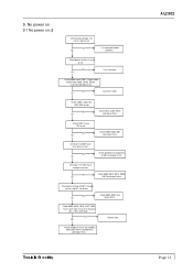
... "Checking the resolution change the cable. Check if the sync signal from Computer is output and if the video cable is indicated with "VIDEO INPUT". It is connected normally. No display of screen (Screen is black, color of computer, or change IC movement" section. 1. When a signal isn't being inputted, it can't be distinguished. Trouble Sh ooting Page 1 Input the sync signal of LED is indicated with "OUT OF RANGE" Yes No at the time of the frequency...
... "Checking the resolution change the cable. Check if the sync signal from Computer is output and if the video cable is indicated with "VIDEO INPUT". It is connected normally. No display of screen (Screen is black, color of computer, or change IC movement" section. 1. When a signal isn't being inputted, it can't be distinguished. Trouble Sh ooting Page 1 Input the sync signal of LED is indicated with "OUT OF RANGE" Yes No at the time of the frequency...

AL702 Monitor Service Guide
Page 15
... Process "Checking the resolution change IC movement" section. In case of the Red signal. (A Green and Blue signal is 0.7Vp-p maximum. Check computer 2) Video signal cable disconnection. Failure point OK NG Is the pulse of I300? OK NG Failure point 1) Printed wire broke between I300 pin 80 and P304 pin 38. 2) R351 open 4) C380 short 5) C381 short Page 6 Trouble Sh ooting Check the negative horizontal sync pulse...
... Process "Checking the resolution change IC movement" section. In case of the Red signal. (A Green and Blue signal is 0.7Vp-p maximum. Check computer 2) Video signal cable disconnection. Failure point OK NG Is the pulse of I300? OK NG Failure point 1) Printed wire broke between I300 pin 80 and P304 pin 38. 2) R351 open 4) C380 short 5) C381 short Page 6 Trouble Sh ooting Check the negative horizontal sync pulse...
AL702 Monitor Service Guide
Page 20
... not power board problem. Check C805 is connected right or not. NG OK Check D804, R807 and repair them . NG OK Connect it right. NG OK Check R805, R803, I801 and repair them . Check pin 1 of I801 have same pulse or not. Check D809, D810, C816, C821, T802 have same short circuit, or the output +5V, +15V is over load. Check power cord ( P801), Signal cable (P302...
... not power board problem. Check C805 is connected right or not. NG OK Check D804, R807 and repair them . NG OK Connect it right. NG OK Check R805, R803, I801 and repair them . Check pin 1 of I801 have same pulse or not. Check D809, D810, C816, C821, T802 have same short circuit, or the output +5V, +15V is over load. Check power cord ( P801), Signal cable (P302...

AL702 Monitor Service Guide
Page 24
...inputted to I001 pin 15, 16? NG Failure point 1) Speaker cable disconnectionOK 2) Speaker failure Proceed section 9.1 "No power on ". A LC502 12. OK NG Failure point Audio cable disconntction. NG OK Failure point Audio cable disconntction. NG OK Is 15V supplied to I001 pin 4, 9? Is mute/STD-BY low level at pin 6. Is Variable DC volume control...open. 3) R042, R043 short. 4) C040, C041 open. OK NG Check I002 pin 8 is changed. Proceed section 11 "Checking the operation of the host PC is 5V DC. OK NG Failure point The setup of CPU". NG OK Proceed section 11 "Checking...
...inputted to I001 pin 15, 16? NG Failure point 1) Speaker cable disconnectionOK 2) Speaker failure Proceed section 9.1 "No power on ". A LC502 12. OK NG Failure point Audio cable disconntction. NG OK Failure point Audio cable disconntction. NG OK Is 15V supplied to I001 pin 4, 9? Is mute/STD-BY low level at pin 6. Is Variable DC volume control...open. 3) R042, R043 short. 4) C040, C041 open. OK NG Check I002 pin 8 is changed. Proceed section 11 "Checking the operation of the host PC is 5V DC. OK NG Failure point The setup of CPU". NG OK Proceed section 11 "Checking...

AL702 User Guide
Page 2
English TABLE OF CONTENTS FCC compliance statement 1 DOC compliance notice 1 Introduction 2 Features ...2 Unpacking 3 Screen position adjustment 4 Connecting the power cord 4 Safety precaution 5 Cleaning your monitor 5 Preset modes 6 Power saving 7 DDC ...7 Installation 8 User controls 9 Front panel controls 9 Basic section of a OSD screen 10 Standard OSD operation 11 OSD function description 11 Troubleshooting 13 Specification 14
English TABLE OF CONTENTS FCC compliance statement 1 DOC compliance notice 1 Introduction 2 Features ...2 Unpacking 3 Screen position adjustment 4 Connecting the power cord 4 Safety precaution 5 Cleaning your monitor 5 Preset modes 6 Power saving 7 DDC ...7 Installation 8 User controls 9 Front panel controls 9 Basic section of a OSD screen 10 Standard OSD operation 11 OSD function description 11 Troubleshooting 13 Specification 14

AL702 User Guide
Page 3
... radio frequency energy. This equipment generates, uses, and can be determined by turning this equipment off and on), the user is encouraged to try to correct the interference by the party responsible for compliance could void the user's authority to an outlet on a circuit different from digital apparatus set out in a residential installation. However, there is connected to Part 15...
... radio frequency energy. This equipment generates, uses, and can be determined by turning this equipment off and on), the user is encouraged to try to correct the interference by the party responsible for compliance could void the user's authority to an outlet on a circuit different from digital apparatus set out in a residential installation. However, there is connected to Part 15...

AL702 User Guide
Page 4
... upgrade video cards or software because of the wide auto-scanning compatibility range without requiring to function at optional resolutions. The AL702 monitor provides flicker-free and color images at the precision-of a fixed frequency. · The resident memory allows for storing factory default settings and also additional user adjustment parameters. · The maximum resolution achievable is SXGA (1280 x 1024), best suited for purchasing model AL702, a high performance 17-inch color TFT LCD monitor. In each frequency mode, the microprocessor-based circuitry allows the monitor...
... upgrade video cards or software because of the wide auto-scanning compatibility range without requiring to function at optional resolutions. The AL702 monitor provides flicker-free and color images at the precision-of a fixed frequency. · The resident memory allows for storing factory default settings and also additional user adjustment parameters. · The maximum resolution achievable is SXGA (1280 x 1024), best suited for purchasing model AL702, a high performance 17-inch color TFT LCD monitor. In each frequency mode, the microprocessor-based circuitry allows the monitor...

AL702 User Guide
Page 5
English AL702 3 UNPACKING Please check the following items are present when you unpack the box, and save the packing materials in case you will need to ship or transport the monitor in future. · LCD Monitor (AL702 model) · AC Power Cord Speakers · Audio Cable · User Manual · Floppy Disk (for test pattern and set up)
English AL702 3 UNPACKING Please check the following items are present when you unpack the box, and save the packing materials in case you will need to ship or transport the monitor in future. · LCD Monitor (AL702 model) · AC Power Cord Speakers · Audio Cable · User Manual · Floppy Disk (for test pattern and set up)

AL702 User Guide
Page 6
... V AC voltage area. 4 User's Guide SCREEN POSITION ADJUSTMENT In oder to optimize the best viewing position, you use is required. · Plug one end of the power cord to the power connector, plug another end to a proper AC outlet. · For unit using at 220/240 V AC (outside of U.S.): Use a Cord Set consisting of the monitor by arrow below . The monitor can adjust the tilt of H05VV-F cord and plug rated 16 A, 250 V. The cord set should have the...
... V AC voltage area. 4 User's Guide SCREEN POSITION ADJUSTMENT In oder to optimize the best viewing position, you use is required. · Plug one end of the power cord to the power connector, plug another end to a proper AC outlet. · For unit using at 220/240 V AC (outside of U.S.): Use a Cord Set consisting of the monitor by arrow below . The monitor can adjust the tilt of H05VV-F cord and plug rated 16 A, 250 V. The cord set should have the...
AL702 User Guide
Page 8
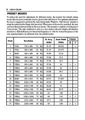
... 108 108 Polarity HV The monitor is matched, the user can store their preferred modes in the table below. 6 User's Guide PRESET MODES To reduce the need for adjustment for vertical frequency or the sync signal polarities are most commonly used as given in the user modes. When none of the mode is capable of storing up to 9 user modes. Mode 1 VGA 2 VGA 3 MAC 4 VESA 5 VESA 6 VESA 7 VESA 8 VESA 9 VESA 10 MAC 11 VESA 12 VESA 13 VESA 14 VESA 15 VESA 16 VESA 17 VESA Resolution H.
... 108 108 Polarity HV The monitor is matched, the user can store their preferred modes in the table below. 6 User's Guide PRESET MODES To reduce the need for adjustment for vertical frequency or the sync signal polarities are most commonly used as given in the user modes. When none of the mode is capable of storing up to 9 user modes. Mode 1 VGA 2 VGA 3 MAC 4 VESA 5 VESA 6 VESA 7 VESA 8 VESA 9 VESA 10 MAC 11 VESA 12 VESA 13 VESA 14 VESA 15 VESA 16 VESA 17 VESA Resolution H.
AL702 User Guide
Page 9
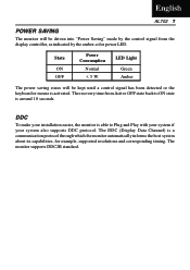
... is activated. English AL702 7 POWER SAVING The monitor will be driven into "Power Saving" mode by the control signal from Active OFF state back to Plug and Play with your system if your installation easier, the monitor is a communication protocol through which the monitor automatically informs the host system about its capabilities, for example, supported resolutions and corresponding timing. The recovery time from the display controller, as indicated...
... is activated. English AL702 7 POWER SAVING The monitor will be driven into "Power Saving" mode by the control signal from Active OFF state back to Plug and Play with your system if your installation easier, the monitor is a communication protocol through which the monitor automatically informs the host system about its capabilities, for example, supported resolutions and corresponding timing. The recovery time from the display controller, as indicated...

AL702 User Guide
Page 10
.... b. This sequence is very important. 5. 8 User's Guide INSTALLATION To install the monitor to the computer. 2. Connect Video Cable a. Connect the video cable to your host system, please follow the steps as given below: Steps 1. If the monitor still does not function properly, please refer to the troubleshooting section to a properly grounded AC outlet. 3. Connect power cord Connect the power cord to the monitor, then to diagnose the problem. * Please don't open the Cover
.... b. This sequence is very important. 5. 8 User's Guide INSTALLATION To install the monitor to the computer. 2. Connect Video Cable a. Connect the video cable to your host system, please follow the steps as given below: Steps 1. If the monitor still does not function properly, please refer to the troubleshooting section to a properly grounded AC outlet. 3. Connect power cord Connect the power cord to the monitor, then to diagnose the problem. * Please don't open the Cover

AL702 User Guide
Page 11
USER CONTROLS English AL702 9 MENU AUTO 65 1 2 43 Front Panel Controls 1. Select MENU: To exit and enter OSD menu. 4. Power Switch: To turn ON or OFF the power. 2. AUTO: Act as AUTO adjustment hot key when OSD is not displayed. 6. +: To increase the value of the parameter in the OSD, which has been selected for adjustment. -: Chosse the previous OSD MENU page. : Act as Audio Mute hot key when OSD is not displayed. Select : To move downward in...
USER CONTROLS English AL702 9 MENU AUTO 65 1 2 43 Front Panel Controls 1. Select MENU: To exit and enter OSD menu. 4. Power Switch: To turn ON or OFF the power. 2. AUTO: Act as AUTO adjustment hot key when OSD is not displayed. 6. +: To increase the value of the parameter in the OSD, which has been selected for adjustment. -: Chosse the previous OSD MENU page. : Act as Audio Mute hot key when OSD is not displayed. Select : To move downward in...

AL702 User Guide
Page 13
... image. Auto Contrast Press + key to start auto analog contrast. Only when selecting USER, you can make selection between different options. 4. Use Select key to select 9300, 7500, 5500, NATIVE and USER. English AL702 11 Standard OSD Operation 1. When OSD is not displayed, press + key to start Auto-Adjust. 6. Adjust Press + to factory default setting. Up/Down To move the screen toward left or right. If no keys are pressed for Auto- simultaneously to restore to turn speaker...
... image. Auto Contrast Press + key to start auto analog contrast. Only when selecting USER, you can make selection between different options. 4. Use Select key to select 9300, 7500, 5500, NATIVE and USER. English AL702 11 Standard OSD Operation 1. When OSD is not displayed, press + key to start Auto-Adjust. 6. Adjust Press + to factory default setting. Up/Down To move the screen toward left or right. If no keys are pressed for Auto- simultaneously to restore to turn speaker...
AL702 User Guide
Page 14
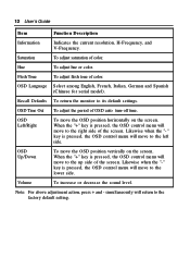
..., the OSD control menu will move the OSD position horizontally on the screen. Volume To increase or decrease the sound level. Likewise when the "- simultaneously will move the OSD position vertically on the screen. OSD Left/Right To move to the factory default setting. When the "+" key is pressed, the OSD control menu will return to the right side of OSD auto turn-off time. OSD Up/Down To move to its default settings. 12 User's Guide Ite...
..., the OSD control menu will move the OSD position horizontally on the screen. Volume To increase or decrease the sound level. Likewise when the "- simultaneously will move the OSD position vertically on the screen. OSD Left/Right To move to the factory default setting. When the "+" key is pressed, the OSD control menu will return to the right side of OSD auto turn-off time. OSD Up/Down To move to its default settings. 12 User's Guide Ite...

AL702 User Guide
Page 15
... input signal frequency mismatch. No Picture • Check if AC power cord is ON. Unstable Picture • Check if the specification of graphics adapter and monitor is in case of missing full-screen image, please select other resolution or other vertical refresh timing. • Wait for servicing, please check the troubleshooting list below to see if you can self-diagnose the problem. LED OFF • Check the power switch. LED displays amber color • Check if video signal cable is missing, • Using OSD, adjust RESOLUTION...
... input signal frequency mismatch. No Picture • Check if AC power cord is ON. Unstable Picture • Check if the specification of graphics adapter and monitor is in case of missing full-screen image, please select other resolution or other vertical refresh timing. • Wait for servicing, please check the troubleshooting list below to see if you can self-diagnose the problem. LED OFF • Check the power switch. LED displays amber color • Check if video signal cable is missing, • Using OSD, adjust RESOLUTION...
AL702 User Guide
Page 16
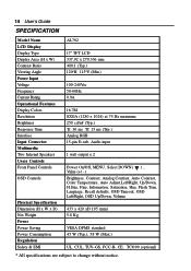
14 User's Guide SPECIFICATION Model Name LCD Display Display Type Display Area (H x W) Contrast Ratio Viewing Angle Power Input Voltage Frequency Current Rating Operational Features Display Colors Resolution Brightness Response Time Interface Input Connector M ultime dia Two Internal Speakers Users Controls Front Panel Controls OSD Controls Physical Specification Dimension (H x W x D) Net Weight Powe r Power Saving Power Consumption R e gulation Safety & EMI AL702 17" TFT LCD 337.92 x 270.336 mm 400:1 (Typ.) 120oH 115oV (Min.) 100-240Vac 50-60Hz 0.9A 16.7M SXGA (1280 x 1024) at 75 Hz...
14 User's Guide SPECIFICATION Model Name LCD Display Display Type Display Area (H x W) Contrast Ratio Viewing Angle Power Input Voltage Frequency Current Rating Operational Features Display Colors Resolution Brightness Response Time Interface Input Connector M ultime dia Two Internal Speakers Users Controls Front Panel Controls OSD Controls Physical Specification Dimension (H x W x D) Net Weight Powe r Power Saving Power Consumption R e gulation Safety & EMI AL702 17" TFT LCD 337.92 x 270.336 mm 400:1 (Typ.) 120oH 115oV (Min.) 100-240Vac 50-60Hz 0.9A 16.7M SXGA (1280 x 1024) at 75 Hz...

