
User Manual
Page 2
... rights are designed to provide reasonable protection against harmful interference in this manual may cause harmful interference to operate the equipment. Warning Use only shielded signal cables to connect I/O devices to this document has been carefully checked for comliance could void your authority to radio communications.
... rights are designed to provide reasonable protection against harmful interference in this manual may cause harmful interference to operate the equipment. Warning Use only shielded signal cables to connect I/O devices to this document has been carefully checked for comliance could void your authority to radio communications.

User Manual
Page 3
... on again to the display. 4. Important Safety Instructions Please read the following occurs, immediately unplug your monitor and call an authorized technician. * Monitor to PC signal cable is frayed or damaged. * Liquid spilled into LCD Monitor or the monitor has been exposed to service this range could result in a room with...
... on again to the display. 4. Important Safety Instructions Please read the following occurs, immediately unplug your monitor and call an authorized technician. * Monitor to PC signal cable is frayed or damaged. * Liquid spilled into LCD Monitor or the monitor has been exposed to service this range could result in a room with...

User Manual
Page 5
.... Figure 1-3 Figure 1-4 Figure 1-5 Power Management System This LCD Monitor complies with the VESA DPMS (version 1.0) Power Management guidelines. Make sure connections are secure. signal. The rear of the signal cable to the D-SUB or DVI (option) port on your computer. 2. Connecting the Display 1. Connect the power cord to the LCD Monitor's D-SUB... as illustrated in power saving mode, the monitor screen will be blank and the power LED indicator will light yellow. 5 Connect one end of the signal cable to the LCD Monitor. (See Fig. 1-5) 2.
.... Figure 1-3 Figure 1-4 Figure 1-5 Power Management System This LCD Monitor complies with the VESA DPMS (version 1.0) Power Management guidelines. Make sure connections are secure. signal. The rear of the signal cable to the D-SUB or DVI (option) port on your computer. 2. Connecting the Display 1. Connect the power cord to the LCD Monitor's D-SUB... as illustrated in power saving mode, the monitor screen will be blank and the power LED indicator will light yellow. 5 Connect one end of the signal cable to the LCD Monitor. (See Fig. 1-5) 2.
User Manual
Page 10
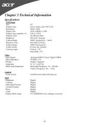
... Panel Size Display Type Resolution Display Dot Display Area (mm)(H x V) Display Color Brightness Contrast Ratio Response Time Lamp Voltage Lamp Current Viewing Angle Video Input Signal Input Impedance Polarity Amplitude Multi-mode Supported Control Power switch OSD Brightness Contrast Horizontal Position Vertical Position Phase Clock Display Mode Setup 24" Active matrix...
... Panel Size Display Type Resolution Display Dot Display Area (mm)(H x V) Display Color Brightness Contrast Ratio Response Time Lamp Voltage Lamp Current Viewing Angle Video Input Signal Input Impedance Polarity Amplitude Multi-mode Supported Control Power switch OSD Brightness Contrast Horizontal Position Vertical Position Phase Clock Display Mode Setup 24" Active matrix...
User Manual
Page 11
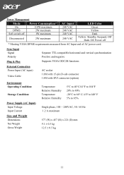
Sync Input Signal Polarity Plug & Play Separate TTL compatible horizontal and vertical synchronization Positive and negative Supports VESA DDC2B functions External Connection Power Input (AC input) Video Cable ...
Sync Input Signal Polarity Plug & Play Separate TTL compatible horizontal and vertical synchronization Positive and negative Supports VESA DDC2B functions External Connection Power Input (AC input) Video Cable ...
User Manual
Page 12
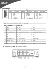
... Ground (+5V) 8 NC 16 Hot plug detect Pin assignment for DVI - Pin Assignment 6 PIN 1 11 1 2 5 15 3 4 10 5 Description Red Green Blue Digital GND Digital GND Signal PIN Description 6 Red Rtn 7 Green Rtn 8 Blue Rtn 9 +5V 10 Hot Plug Detect PIN Description 11 NC 12 SDA 13 H. D (option) Pin -
... Ground (+5V) 8 NC 16 Hot plug detect Pin assignment for DVI - Pin Assignment 6 PIN 1 11 1 2 5 15 3 4 10 5 Description Red Green Blue Digital GND Digital GND Signal PIN Description 6 Red Rtn 7 Green Rtn 8 Blue Rtn 9 +5V 10 Hot Plug Detect PIN Description 11 NC 12 SDA 13 H. D (option) Pin -

User Manual
Page 15
...most clear display. 4. PROBLEM There is no picture on the LCD Monitor is unclear and unstable, please perform the following steps: 1. Also, if the signal cable is no picture on the LCD Monitor, please perform the following steps : 1. Move to "Phase" function in the market, users may be out...for a listing of the LCD Monitor's synchronous range (Horizontal: 24 ~ 80 KHz and Vertical: 49 ~ 75 Hz), the OSD will display a message "No Input Signal". 15 If there are secured, and the system is running on "Shut Down Windows" and back to "Shut Down Windows" status while you have chosen...
...most clear display. 4. PROBLEM There is no picture on the LCD Monitor is unclear and unstable, please perform the following steps: 1. Also, if the signal cable is no picture on the LCD Monitor, please perform the following steps : 1. Move to "Phase" function in the market, users may be out...for a listing of the LCD Monitor's synchronous range (Horizontal: 24 ~ 80 KHz and Vertical: 49 ~ 75 Hz), the OSD will display a message "No Input Signal". 15 If there are secured, and the system is running on "Shut Down Windows" and back to "Shut Down Windows" status while you have chosen...


