
AL1951 Service Guide
Page 7
... time. Special Notes On LCD Monitors The following symptoms are normal with LCD monitor and do not indicate a problem. In this case, the screen is displayed for hours. 7 Notes Due to make sure the flicker disappears. You may flicker during initial use . Turn off the Power Switch for hours.
... time. Special Notes On LCD Monitors The following symptoms are normal with LCD monitor and do not indicate a problem. In this case, the screen is displayed for hours. 7 Notes Due to make sure the flicker disappears. You may flicker during initial use . Turn off the Power Switch for hours.

AL1951 Service Guide
Page 12
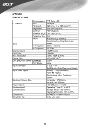
L01) Display Type active matrix color TFT LCD Resolution 1280x1024 pixels Display Dot 1280x (RGB) x 1024 Display Area 376.32mm(H) x 301.056mm(V) Pixel Pitch 0.294mm(H) x 0.294mm(V) Display Color 16.7M (true) Lamp Frequency 80kHz (Max) Lamp Current 8.0 mArms (Max) Weight 2250g (Max) Optical Specifications IL = 6.5mArms Ta = 25 2¢C VDD = 5V FV = 60Hz FDCLK = 54MHz 12 LCD Panel Specification LCD Panel Model (SAMSUNG LTM190EX-
L01) Display Type active matrix color TFT LCD Resolution 1280x1024 pixels Display Dot 1280x (RGB) x 1024 Display Area 376.32mm(H) x 301.056mm(V) Pixel Pitch 0.294mm(H) x 0.294mm(V) Display Color 16.7M (true) Lamp Frequency 80kHz (Max) Lamp Current 8.0 mArms (Max) Weight 2250g (Max) Optical Specifications IL = 6.5mArms Ta = 25 2¢C VDD = 5V FV = 60Hz FDCLK = 54MHz 12 LCD Panel Specification LCD Panel Model (SAMSUNG LTM190EX-

AL1951 Service Guide
Page 17
... scalar to be able to green color. Scalar initializes. 10) In standby mode? 11) Update the lifetime of brightness from analog or digital port? 16) Display " No Input Signal " message. Is the power key pressed? 10 N Y N 12 Y 11 13 N Y 14 15 N 16 Y 17 18 N 19 Y 17 Software Flow Chart 1 2 Y 3 N 4 5 N Y 6 7 N ...scalar send out a interrupt request? 14) Wake up the scalar. 15) Are there any signals coming mode. 18) Process the OSD display. 19) Read the keyboard. Check the pin PANEL1 and PANEL2 to tell which panel to get with it to show the coming from eeprom....
... scalar to be able to green color. Scalar initializes. 10) In standby mode? 11) Update the lifetime of brightness from analog or digital port? 16) Display " No Input Signal " message. Is the power key pressed? 10 N Y N 12 Y 11 13 N Y 14 15 N 16 Y 17 18 N 19 Y 17 Software Flow Chart 1 2 Y 3 N 4 5 N Y 6 7 N ...scalar send out a interrupt request? 14) Wake up the scalar. 15) Are there any signals coming mode. 18) Process the OSD display. 19) Read the keyboard. Check the pin PANEL1 and PANEL2 to tell which panel to get with it to show the coming from eeprom....

AL1951 Service Guide
Page 26
... 0625, 0821 approval power cord in European counties. 26 The appearance is similar to a "Screen Saver" feature except the display is a unidirectional data channel from the display to the host that power supply cord needs to be 125 volts AC. Supplied with units intended for this monitor, following ... over the DDC2B channel. This monitor meets the Green monitor standards as set consisting of DDC used, communicate additional information about its display capabilities. Using The Right Power Cord The accessory power cord for the power cord shall be non-functional if there is the wallet...
... 0625, 0821 approval power cord in European counties. 26 The appearance is similar to a "Screen Saver" feature except the display is a unidirectional data channel from the display to the host that power supply cord needs to be 125 volts AC. Supplied with units intended for this monitor, following ... over the DDC2B channel. This monitor meets the Green monitor standards as set consisting of DDC used, communicate additional information about its display capabilities. Using The Right Power Cord The accessory power cord for the power cord shall be non-functional if there is the wallet...

AL1951 Service Guide
Page 38
... Monitor Ground DDC-Serial Data H-Sync V-Sync DDC-Serial Clock PIN NO. 1. 2. 3. 4. 5. 6. 7. 8. 9. 10. 11. 12. 24 - Pin Color Display Signal Cable (D-sub) DESCRIPTION Red Green Blue Monitor Ground DDC-Return R-Ground G-Ground B-Ground PI N NO. 9. 10. 11. 12. 13. 14. 15. TMDS ...Data0+ TMDS Data 0/5 Shield TMDS Data5TMDS Data5+ DDC Clock Shield DDC Clock+ DDC Clock- 38 Pin Color Display Signal Cable (DVI) DESCRIPTION TMDS Data2TMDS Data2+ TMDS Data 2/4 Shield TMDS Data4TMDS Data4+ DDC Clock DDC Data Analogue Vertical Sync TMDS Data1TMDS Data1+ TMDS ...
... Monitor Ground DDC-Serial Data H-Sync V-Sync DDC-Serial Clock PIN NO. 1. 2. 3. 4. 5. 6. 7. 8. 9. 10. 11. 12. 24 - Pin Color Display Signal Cable (D-sub) DESCRIPTION Red Green Blue Monitor Ground DDC-Return R-Ground G-Ground B-Ground PI N NO. 9. 10. 11. 12. 13. 14. 15. TMDS ...Data0+ TMDS Data 0/5 Shield TMDS Data5TMDS Data5+ DDC Clock Shield DDC Clock+ DDC Clock- 38 Pin Color Display Signal Cable (DVI) DESCRIPTION TMDS Data2TMDS Data2+ TMDS Data 2/4 Shield TMDS Data4TMDS Data4+ DDC Clock DDC Data Analogue Vertical Sync TMDS Data1TMDS Data1+ TMDS ...

AL1951 User's Guide
Page 4
...'s Manual 3. BEFORE YOU OPERATE THE MONITOR FEATURES • 48cm(19") TFT Color LCD Monitor • Crisp, Clear Display for hours. Power Cord 4. DVI Cable (only Dual-Input Model) 7. In this case, the screen is displayed for Windows • Recommened Resolutions: 1280 X 1024 @60Hz • EPA ENERGY STAR® • Dual Input (DVI...
...'s Manual 3. BEFORE YOU OPERATE THE MONITOR FEATURES • 48cm(19") TFT Color LCD Monitor • Crisp, Clear Display for hours. Power Cord 4. DVI Cable (only Dual-Input Model) 7. In this case, the screen is displayed for Windows • Recommened Resolutions: 1280 X 1024 @60Hz • EPA ENERGY STAR® • Dual Input (DVI...

AL1951 User's Guide
Page 5
... cord according to the wall, see the following diagram for information on the type of monitor; Installing the wall mounting bracket (not included) This monitor display can be used . Connect the AC-power cord into the holes as shown in the bracket and on the underside of the wall mounting bracket...
... cord according to the wall, see the following diagram for information on the type of monitor; Installing the wall mounting bracket (not included) This monitor display can be used . Connect the AC-power cord into the holes as shown in the bracket and on the underside of the wall mounting bracket...

AL1951 User's Guide
Page 9
... OFF or navigate through adjustment icons when OSD is ON or adjust a function when function is used to turn the monitor ON or OFF, And display the monitor's state. • Power Indicator: Blue -
... OFF or navigate through adjustment icons when OSD is ON or adjust a function when function is used to turn the monitor ON or OFF, And display the monitor's state. • Power Indicator: Blue -

AL1951 User's Guide
Page 13
...on the I2C protocol. Supplied with units intended for connection to inform the host system of its display capabilities. After the video input signal is restored, full power is restored and the display is UL listed and CSA labeled. USING THE RIGHT POWER CORD : The accessory power cord for...It allows the monitor to power outlet of personal computer: Please use VDE 0602, 0625, 0821 approval power cord in European counties. 12 The display is equipped with NEMA 5-15 style and is automatically redrawn. Please note that power supply cord needs to the VESA DDC STANDARD. PLUG AND...
...on the I2C protocol. Supplied with units intended for connection to inform the host system of its display capabilities. After the video input signal is restored, full power is restored and the display is UL listed and CSA labeled. USING THE RIGHT POWER CORD : The accessory power cord for...It allows the monitor to power outlet of personal computer: Please use VDE 0602, 0625, 0821 approval power cord in European counties. 12 The display is equipped with NEMA 5-15 style and is automatically redrawn. Please note that power supply cord needs to the VESA DDC STANDARD. PLUG AND...

AL1951 User's Guide
Page 16
INPUT NOT SUPPORT : Your computer has been set to unsuitable display mode ,set the computer to display mode given in the following table(See page 18). 15 ERROR MESSAGE & POSSIBLE SOLUTION CABLE NOT CONNECTED : 1. Check the signal -cable connection pins for damage. Check that the signal-cable is properly connected , If the connector is loose, tighten the connector's screws. 2.
INPUT NOT SUPPORT : Your computer has been set to unsuitable display mode ,set the computer to display mode given in the following table(See page 18). 15 ERROR MESSAGE & POSSIBLE SOLUTION CABLE NOT CONNECTED : 1. Check the signal -cable connection pins for damage. Check that the signal-cable is properly connected , If the connector is loose, tighten the connector's screws. 2.
AL1951 User's Guide
Page 17
...) Viewable angle 150° (H) 135° (V) Response time 8ms Video R,G,B Analog Interface Digital interface(Only Dual-Input Input Model) H-Frequency 30KHz - 80KHz V-Frequency 55-75Hz Display Colors 16.2M Colors Dot Clock 135MHz Max. Resolution 1280 x 1024 @75Hz Plug & Play VESA DDC2BTM EPA ENERGY STAR® ON Mode ≤50W OFF...
...) Viewable angle 150° (H) 135° (V) Response time 8ms Video R,G,B Analog Interface Digital interface(Only Dual-Input Input Model) H-Frequency 30KHz - 80KHz V-Frequency 55-75Hz Display Colors 16.2M Colors Dot Clock 135MHz Max. Resolution 1280 x 1024 @75Hz Plug & Play VESA DDC2BTM EPA ENERGY STAR® ON Mode ≤50W OFF...

AL1951 User's Guide
Page 18
timeout • Display information • Exit 50 Watts Rated Power 1.5W rms (Per channel) CUL, FCC, VCCI, CCC, MPR II, CE, TÜV/GS, TCO'99, UL, ISO13406-2 17 ...
timeout • Display information • Exit 50 Watts Rated Power 1.5W rms (Per channel) CUL, FCC, VCCI, CCC, MPR II, CE, TÜV/GS, TCO'99, UL, ISO13406-2 17 ...


