
AL1912 Service Guide
Page 7
......8 ELECTRICAL REQUIREMEENTS...9 MONITOR BLOCK DIAGRAM ...15 BLOCK DIAGRAM ...16 MONITOR BOARD LAYOUT ...17 SOFTWARE FLOW CHART ...18 GENERAL INSTRUCTIONS ...19 SYSTEM INSTALLATION ...20 POWER/INVERTOR BOARD ...25 ELECTRICAL SPECIFICATION...26 INVERTER ELECTRICAL SPECIFICATION ...28 SAFETY ...28 Chapter... 2 Operating Instruction 30 CONTROLS ...30 MAIN OSD MENU...31 OSD MESSAGE...33 PLUG AND PLAY ...35 WHITE COLOR TEMPERATURE...36 AUDIO TECHNICAL SPECIFICATION (FOR AL1912...
......8 ELECTRICAL REQUIREMEENTS...9 MONITOR BLOCK DIAGRAM ...15 BLOCK DIAGRAM ...16 MONITOR BOARD LAYOUT ...17 SOFTWARE FLOW CHART ...18 GENERAL INSTRUCTIONS ...19 SYSTEM INSTALLATION ...20 POWER/INVERTOR BOARD ...25 ELECTRICAL SPECIFICATION...26 INVERTER ELECTRICAL SPECIFICATION ...28 SAFETY ...28 Chapter... 2 Operating Instruction 30 CONTROLS ...30 MAIN OSD MENU...31 OSD MESSAGE...33 PLUG AND PLAY ...35 WHITE COLOR TEMPERATURE...36 AUDIO TECHNICAL SPECIFICATION (FOR AL1912...
AL1912 Service Guide
Page 15
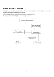
The Adapter will drive the backlight of panel and the DC-DC conversion. The inverter board will provide thr 12V DC-power to inverter/ power board. Power board (include: AC/DC,inverter) - 15 - MONITOR BLOCK DIAGRAM The LCD monitor will contain an main board, an inverter/ power board, key board and internal adapter which house the flat panel control logic, brightness control logic and DDC.
The Adapter will drive the backlight of panel and the DC-DC conversion. The inverter board will provide thr 12V DC-power to inverter/ power board. Power board (include: AC/DC,inverter) - 15 - MONITOR BLOCK DIAGRAM The LCD monitor will contain an main board, an inverter/ power board, key board and internal adapter which house the flat panel control logic, brightness control logic and DDC.

AL1912 Service Guide
Page 25
... current: 1.2Amax. Audio ground Ground Ground Brightness control from logical board (0V to 3.3V) ----Inverter enable signal from logical board (high active , >3V) +5Vdc supply for logical board +5Vdc supply for logical board +5Vdc supply for logical board - 25 - at 90Vac Input Frequency: 47 ~ 63Hz Input power saving consumption: Less than 1.2W @ minimum load Total output...
... current: 1.2Amax. Audio ground Ground Ground Brightness control from logical board (0V to 3.3V) ----Inverter enable signal from logical board (high active , >3V) +5Vdc supply for logical board +5Vdc supply for logical board +5Vdc supply for logical board - 25 - at 90Vac Input Frequency: 47 ~ 63Hz Input power saving consumption: Less than 1.2W @ minimum load Total output...
AL1912 Service Guide
Page 39
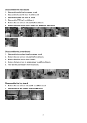
... the three screws from VL board. 4. Then take the power board from power board. 2. Remove the one screw to release power board from Chassis. 5. Disassemble audio line from the chassia. Disassemble two voltage lines from VK board. 39 Remove the two screws to release VK board from Chassis. 3. Disassemble the two speaker lines from power board. 2. Remove the one screw to...
... the three screws from VL board. 4. Then take the power board from power board. 2. Remove the one screw to release power board from Chassis. 5. Disassemble audio line from the chassia. Disassemble two voltage lines from VK board. 39 Remove the two screws to release VK board from Chassis. 3. Disassemble the two speaker lines from power board. 2. Remove the one screw to...


