AL1751 Service Guide
Page 5
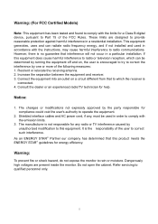
...; Partner our company has determined that this product meets the ENERGY STAR® guidelines for help. These limits are present inside the monitor. Increase the separation between the equipment and receiver. 3. Notice: 1. It is no guarantee that to which the receiver is not ...a particular installation. The manufacturer is connected. 4. If this equipment. Warning: To prevent fire or shock hazard, do not expose the monitor to Part 15 of the user to radio communications. The changes or modifications not expressly approved by unauthorized modification to qualified personnel only. 5...
...; Partner our company has determined that this product meets the ENERGY STAR® guidelines for help. These limits are present inside the monitor. Increase the separation between the equipment and receiver. 3. Notice: 1. It is no guarantee that to which the receiver is not ...a particular installation. The manufacturer is connected. 4. If this equipment. Warning: To prevent fire or shock hazard, do not expose the monitor to Part 15 of the user to radio communications. The changes or modifications not expressly approved by unauthorized modification to qualified personnel only. 5...
AL1751 Service Guide
Page 6
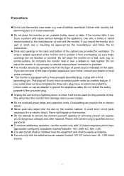
...electric shock. opening or removing covers can injure a person and cause serious damage to ground the appliance safely. Do not place the monitor on the monitor. Slots and openings in a bookcase or cabinet unless proper ventilation is equipped with a three-pronged grounded plug, a plug with the... of power supplied to qualified service personnel To ensure satisfactory operation, use only with a third (grounding) pin. Do not place the monitor on the label. The wall socket shall be installed near or over a radiator or heat register. Unplug the unit during a lightning ...
...electric shock. opening or removing covers can injure a person and cause serious damage to ground the appliance safely. Do not place the monitor on the monitor. Slots and openings in a bookcase or cabinet unless proper ventilation is equipped with a three-pronged grounded plug, a plug with the... of power supplied to qualified service personnel To ensure satisfactory operation, use only with a third (grounding) pin. Do not place the monitor on the label. The wall socket shall be installed near or over a radiator or heat register. Unplug the unit during a lightning ...
AL1751 Service Guide
Page 7
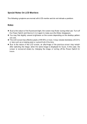
... slowly by changing the image or turning off the Power Switch and then turn it on the desktop pattern you use . Special Notes On LCD Monitors The following symptoms are normal with LCD...
... slowly by changing the image or turning off the Power Switch and then turn it on the desktop pattern you use . Special Notes On LCD Monitors The following symptoms are normal with LCD...
AL1751 Service Guide
Page 8
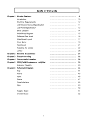
Table Of Contents Chapter 1 Monitor Features Introduction Electrical Requirements LCD Monitor General Specification LCD Panel Specification Block Diagram Main Board Diagram Software Flow chart Main Board Layout Front Bezel Rear Bezel Adjusting the picture LOGO Chapter 2 ...
Table Of Contents Chapter 1 Monitor Features Introduction Electrical Requirements LCD Monitor General Specification LCD Panel Specification Block Diagram Main Board Diagram Software Flow chart Main Board Layout Front Bezel Rear Bezel Adjusting the picture LOGO Chapter 2 ...

AL1751 Service Guide
Page 9
... pin D-sub VGA connector and 24 pin DVI connector. It also supports VESA DPMS power management and plug & play function. This monitor can be directly connected to drive a pair of AL1751 Panel Signal Interface Sync Type Color Temp User Adjust DDC Speaker Headphone Jack Microphone Jack USB Hub Tilt / Swivel 17" SEC...
... pin D-sub VGA connector and 24 pin DVI connector. It also supports VESA DPMS power management and plug & play function. This monitor can be directly connected to drive a pair of AL1751 Panel Signal Interface Sync Type Color Temp User Adjust DDC Speaker Headphone Jack Microphone Jack USB Hub Tilt / Swivel 17" SEC...
AL1751 Service Guide
Page 10
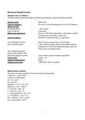
.../white balance and Blue/white balance control : Power input : Ambient temperature : Analog input mode : Set to Factory preset value (cut off raster) T Set to the monitor under the following conditions, unless otherwise specified. In the center (unless otherwise specified) 230V 5Ċ 20+5¥ 1280x1024, 60 Hz, all white Measurement systems The...
.../white balance and Blue/white balance control : Power input : Ambient temperature : Analog input mode : Set to Factory preset value (cut off raster) T Set to the monitor under the following conditions, unless otherwise specified. In the center (unless otherwise specified) 230V 5Ċ 20+5¥ 1280x1024, 60 Hz, all white Measurement systems The...
AL1751 Service Guide
Page 14
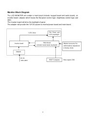
Monitor Block Diagram The LCD MONITOR will drive the backlight of panel. The Inverter board will contain a main board (include: keypad board and audio board), an inverter board, adapter which house the flat panel control logic, brightness control logic and DDC. Flat Panel and CCFL backlight Inverter board Adapter AC-IN 100V-240V Main Board (Include: Audio board, keyboard) RS232 Connector For white balance adjustment in factory mode HOST Computer Video signal, DDC 14 The adapter will provide the 12V DC-power to inverter/power board and main board. CCFL Drive.
Monitor Block Diagram The LCD MONITOR will drive the backlight of panel. The Inverter board will contain a main board (include: keypad board and audio board), an inverter board, adapter which house the flat panel control logic, brightness control logic and DDC. Flat Panel and CCFL backlight Inverter board Adapter AC-IN 100V-240V Main Board (Include: Audio board, keyboard) RS232 Connector For white balance adjustment in factory mode HOST Computer Video signal, DDC 14 The adapter will provide the 12V DC-power to inverter/power board and main board. CCFL Drive.
AL1751 Service Guide
Page 26
...data channel from the display to the host that power supply cord needs to inform the host system of its display capabilities. This monitor meets the Green monitor standards as set consisting of DDC used, communicate additional information about its identity and, depending on the level of a minimum No.... 18 AWG, type SJT or SVT three conductors flexible cord. It allows the monitor to use a cord set by the Video Electronics Standards Association (VESA) and/or the United States Environmental Protection Agency (EPA) and The ...
...data channel from the display to the host that power supply cord needs to inform the host system of its display capabilities. This monitor meets the Green monitor standards as set consisting of DDC used, communicate additional information about its identity and, depending on the level of a minimum No.... 18 AWG, type SJT or SVT three conductors flexible cord. It allows the monitor to use a cord set by the Video Electronics Standards Association (VESA) and/or the United States Environmental Protection Agency (EPA) and The ...
AL1751 Service Guide
Page 27
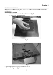
Disassembly Procedure 1. Remove two screws to assemble the monitor for maintenance. Chapter 2 Machine Disassembly This chapter contains step-by-step procedures on how to release back cover. (Fig 1). 2. Remove four screws to release front bezel. (Fig 3) 4. Remove the hinge cap. (Fig 4) 27 Remove the base stand (Fig 2) Fig 1 Fig2 3.
Disassembly Procedure 1. Remove two screws to assemble the monitor for maintenance. Chapter 2 Machine Disassembly This chapter contains step-by-step procedures on how to release back cover. (Fig 1). 2. Remove four screws to release front bezel. (Fig 3) 4. Remove the hinge cap. (Fig 4) 27 Remove the base stand (Fig 2) Fig 1 Fig2 3.
AL1751 Service Guide
Page 38
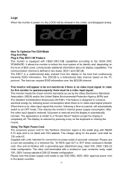
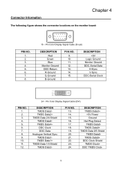
... 5. 6. 7. 8. 1 5 6 10 11 15 15 - PI N NO. 13. 14. 15. 16. 17. 18. 19. 20. 21. 22. 23. 24. DESCRIPTION +5V Logic Ground Monitor Ground DDC-Serial Data H-Sync V-Sync DDC-Serial Clock PIN NO. 1. 2. 3. 4. 5. 6. 7. 8. 9. 10. 11. 12. 24 - Pin Color Display Signal Cable (DVI) DESCRIPTION TMDS Data2TMDS Data2...Data 0/5 Shield TMDS Data5TMDS Data5+ DDC Clock Shield TMDS Clock+ DDC TMDS Clock- 38 Pin Color Display Signal Cable (D-sub) DESCRIPTION Red Green Blue Monitor Ground DDC-Return R-Ground G-Ground B-Ground PI N NO. 9. 10. 11. 12. 13. 14. 15. DESCRIPTION TMDS Data3+ +5V Power ...
... 5. 6. 7. 8. 1 5 6 10 11 15 15 - PI N NO. 13. 14. 15. 16. 17. 18. 19. 20. 21. 22. 23. 24. DESCRIPTION +5V Logic Ground Monitor Ground DDC-Serial Data H-Sync V-Sync DDC-Serial Clock PIN NO. 1. 2. 3. 4. 5. 6. 7. 8. 9. 10. 11. 12. 24 - Pin Color Display Signal Cable (DVI) DESCRIPTION TMDS Data2TMDS Data2...Data 0/5 Shield TMDS Data5TMDS Data5+ DDC Clock Shield TMDS Clock+ DDC TMDS Clock- 38 Pin Color Display Signal Cable (D-sub) DESCRIPTION Red Green Blue Monitor Ground DDC-Return R-Ground G-Ground B-Ground PI N NO. 9. 10. 11. 12. 13. 14. 15. DESCRIPTION TMDS Data3+ +5V Power ...


