AL1716v Service Guide
Page 6
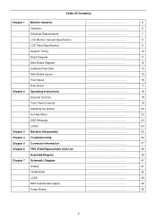
Table Of Contents Chapter 1 Monitor Features 6 Induction 6 Electrical Requirements 7 LCD Monitor General Specification 8 LCD Panel Specification 9 Support Timing 10 Block Diagram 11 Main Board Diagram 12 ... Panel Controls 19 Adjusting the picture 20 Hot-Key Menu 23 OSD Message 23 LOGO 24 Chapter 3 Machine Disassembly 25 Chapter 4 Troubleshooting 32 Chapter 5 Connector Information 37 Chapter 6 FRU (Field Replacement Unit) List 38 Exploded Diagram 39 Chapter 7 Schematic Diagram 41 ...
Table Of Contents Chapter 1 Monitor Features 6 Induction 6 Electrical Requirements 7 LCD Monitor General Specification 8 LCD Panel Specification 9 Support Timing 10 Block Diagram 11 Main Board Diagram 12 ... Panel Controls 19 Adjusting the picture 20 Hot-Key Menu 23 OSD Message 23 LOGO 24 Chapter 3 Machine Disassembly 25 Chapter 4 Troubleshooting 32 Chapter 5 Connector Information 37 Chapter 6 FRU (Field Replacement Unit) List 38 Exploded Diagram 39 Chapter 7 Schematic Diagram 41 ...
AL1716W User's Guide
Page 1
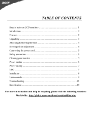
TABLE OF CONTENTS Special notes on LCD monitors 1 Introduction 2 Features ...2 Unpacking 3 Attaching/Removing the base 4 Screen position adjustment 4 Connecting the power cord 5 Safety precaution 5 Cleaning your monitor 5 Preset modes 6 Power saving 7 DDC ...7 Installation 8 User controls 9 Troubleshooting 13 Specification 15 For more information and help in recycling, please visit the following websites: Worldwide: http://global.acer.com/about/sustainability.htm
TABLE OF CONTENTS Special notes on LCD monitors 1 Introduction 2 Features ...2 Unpacking 3 Attaching/Removing the base 4 Screen position adjustment 4 Connecting the power cord 5 Safety precaution 5 Cleaning your monitor 5 Preset modes 6 Power saving 7 DDC ...7 Installation 8 User controls 9 Troubleshooting 13 Specification 15 For more information and help in recycling, please visit the following websites: Worldwide: http://global.acer.com/about/sustainability.htm
AL1716W User's Guide
Page 9
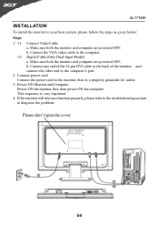
... E-8 b. Connect the VGA video cable to diagnose the problem. b. Make sure both the monitor and computer are powered-OFF. If the monitor still does not function properly, please refer to the troubleshooting section to the computer. 1-2 Digital Cable (Only Dual-Input Model) a. Connect power cord ...Connect the power cord to the monitor, then to your host system, please follow the steps as...
... E-8 b. Connect the VGA video cable to diagnose the problem. b. Make sure both the monitor and computer are powered-OFF. If the monitor still does not function properly, please refer to the troubleshooting section to the computer. 1-2 Digital Cable (Only Dual-Input Model) a. Connect power cord ...Connect the power cord to the monitor, then to your host system, please follow the steps as...
AL1716W User's Guide
Page 14
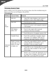
... Wait for servicing, please check the troubleshooting list below to see if you can self-diagnose the problem. (VGA Mode) Problems Current Status Remedy LED ON · Using OSD, adjust brightness and contrast to maximum or reset to the monitor. Display is properly connected to their default...with non-standard signals. · Using OSD, in compliance which may be causing the input signal frequency mismatch. AL1716W TROUBLESHOOTING Before sending your LCD monitor for a few seconds after adjusting the size of the image before changing or disconnecting the signal cable or powering OFF ...
... Wait for servicing, please check the troubleshooting list below to see if you can self-diagnose the problem. (VGA Mode) Problems Current Status Remedy LED ON · Using OSD, adjust brightness and contrast to maximum or reset to the monitor. Display is properly connected to their default...with non-standard signals. · Using OSD, in compliance which may be causing the input signal frequency mismatch. AL1716W TROUBLESHOOTING Before sending your LCD monitor for a few seconds after adjusting the size of the image before changing or disconnecting the signal cable or powering OFF ...
AL1716x Service Guide
Page 9
... Board PCB Layout Front Bezel Rear Cover Chapter 2 Operating Instruction 20 Front Bezel Control Adjusting the Monitor How to Optimize the DOS-Mode Chapter 3 Machine Assembly 27 Chapter 4 Troubleshooting 31 Common Acknowledge Interface Board Troubleshooting QPI PCBA Troubleshooting Chapter 5 Connector Information 40 VGA Connector Pin Assignment Chapter 6 FRU (Field Replaceable Unit) 42 Exploded Diagram...
... Board PCB Layout Front Bezel Rear Cover Chapter 2 Operating Instruction 20 Front Bezel Control Adjusting the Monitor How to Optimize the DOS-Mode Chapter 3 Machine Assembly 27 Chapter 4 Troubleshooting 31 Common Acknowledge Interface Board Troubleshooting QPI PCBA Troubleshooting Chapter 5 Connector Information 40 VGA Connector Pin Assignment Chapter 6 FRU (Field Replaceable Unit) 42 Exploded Diagram...
AL1716x Service Guide
Page 27
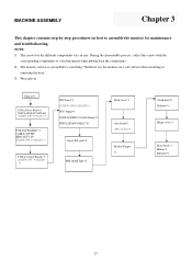
... cover*1 Front bezel*1 Button*1 Indicator*1 27 During the disassembly process, collect the screws with the corresponding components to scratching! The screws for maintenance and troubleshooting. NOTE: 1. The monitor surface is susceptible to avoid mismatch when putting back the components. 2. MACHINE ASSEMBLY Chapter 3 This chapter contains step-by-step procedures on a soft surface...
... cover*1 Front bezel*1 Button*1 Indicator*1 27 During the disassembly process, collect the screws with the corresponding components to scratching! The screws for maintenance and troubleshooting. NOTE: 1. The monitor surface is susceptible to avoid mismatch when putting back the components. 2. MACHINE ASSEMBLY Chapter 3 This chapter contains step-by-step procedures on a soft surface...


