
AL1715 Service Guide
Page 4
... , the user is encouraged to try to which the receiver is no guarantee that interference will not occur in a residential installation. Warning Use only shielded signal cables to connect I/O devices to rain or moisture. You are cautioned that changes or modifications not expressly approved by turning the equipment off and on...
... , the user is encouraged to try to which the receiver is no guarantee that interference will not occur in a residential installation. Warning Use only shielded signal cables to connect I/O devices to rain or moisture. You are cautioned that changes or modifications not expressly approved by turning the equipment off and on...

AL1715 Service Guide
Page 8
... latest LCD technology to general 15 pin D-sub VGA connector and eliminates the requirement of AR577/578 AR577 Panel Normal 17" panel HYDIS HT17E12-200 Signal Interface Sync Type for the 17" MICRO-PROCESSOR based Multi-mode supported high resolution color LCD monitor.
... latest LCD technology to general 15 pin D-sub VGA connector and eliminates the requirement of AR577/578 AR577 Panel Normal 17" panel HYDIS HT17E12-200 Signal Interface Sync Type for the 17" MICRO-PROCESSOR based Multi-mode supported high resolution color LCD monitor.

AL1715 Service Guide
Page 9
...: 1280 x1024 /60 Hz MEASUREMENT SYSTEMS The units of LCD panel Warrn up time All specifications : 30 minutes Fully functional : 5 seconds Measuring Equipment : Chroma 2250 signal generator or equivalent, directly Connected to the monitor under the following conditions, unless otherwise specified. ELECTRICAL REQUIREMENTS Standard Test Conditions All tests shall be performed...
...: 1280 x1024 /60 Hz MEASUREMENT SYSTEMS The units of LCD panel Warrn up time All specifications : 30 minutes Fully functional : 5 seconds Measuring Equipment : Chroma 2250 signal generator or equivalent, directly Connected to the monitor under the following conditions, unless otherwise specified. ELECTRICAL REQUIREMENTS Standard Test Conditions All tests shall be performed...

AL1715 Service Guide
Page 10
... / 80 ( 160 degrees horizontal typical) U / D 65 / 65 ( 130 degrees vertical typical) > 75 % (typical) 1).Video: RGB analog 0.7V peak to peak Sync: TTL positive or negative Signal connector: 15 pin Mini D type, (standard VGA video) 3.5 mm stereo audio jack (Audio) (For AR577 only) Audio power: 0.5Wrms + 0.5Wrms (300Hz - 10kHz (S.P.L. - 10 dB))(AR577...
... / 80 ( 160 degrees horizontal typical) U / D 65 / 65 ( 130 degrees vertical typical) > 75 % (typical) 1).Video: RGB analog 0.7V peak to peak Sync: TTL positive or negative Signal connector: 15 pin Mini D type, (standard VGA video) 3.5 mm stereo audio jack (Audio) (For AR577 only) Audio power: 0.5Wrms + 0.5Wrms (300Hz - 10kHz (S.P.L. - 10 dB))(AR577...
AL1715 Service Guide
Page 12
... input • Type • Input Impedance • Polarity • Amplitude • Display Color Sync input • Signal • Polarity Analog R, G, B. 75 ohm +/- 2% Positive 0 - 0.7 +/- 0.05 Vp same as LCD panel separate horizontal and vertical sync, or composite sync which are TTL compatible positive ...
... input • Type • Input Impedance • Polarity • Amplitude • Display Color Sync input • Signal • Polarity Analog R, G, B. 75 ohm +/- 2% Positive 0 - 0.7 +/- 0.05 Vp same as LCD panel separate horizontal and vertical sync, or composite sync which are TTL compatible positive ...

AL1715 Service Guide
Page 19
... status into standby mode after the message disappear. 17. Wake up the scalar 15. In standby mode? 11. Check the analog port, are there any signal coming from eeprom. 5. Are the "" (Adjust key) and power key. 8. Read the key board. Enter factory mode 9. Turn on the LED and set it to... of brightness from analog port? 16. Is the power key pressed? 6. Does the scalar send out a interrupt request? 14. Software Flow Chart 1. Are there any signals coming mode. 18. Is the eeprom blank? 3.
... status into standby mode after the message disappear. 17. Wake up the scalar 15. In standby mode? 11. Check the analog port, are there any signal coming from eeprom. 5. Are the "" (Adjust key) and power key. 8. Read the key board. Enter factory mode 9. Turn on the LED and set it to... of brightness from analog port? 16. Is the power key pressed? 6. Does the scalar send out a interrupt request? 14. Software Flow Chart 1. Are there any signals coming mode. 18. Is the eeprom blank? 3.

AL1715 Service Guide
Page 21
Connecting the Audio Cable (For AL1715 m and AL1715 bm) Connect the audio cable to the LCD Monitor's VGA port. Connect the other end of the signal cable to the VGA port on your PC's audio card or to the LCD Monitor's " AUDIO IN " jack. - 21 - Connect one end of the audio ...cable to the front panel's "AUDIO OUT" jack of your PC. Connect the other end of the signal cable to the " LINE OUT " jack on your CD ROM drive. Make sure connections are secure. System Installation Connecting the Display Power off your computer...
Connecting the Audio Cable (For AL1715 m and AL1715 bm) Connect the audio cable to the LCD Monitor's VGA port. Connect the other end of the signal cable to the VGA port on your PC's audio card or to the LCD Monitor's " AUDIO IN " jack. - 21 - Connect one end of the audio ...cable to the front panel's "AUDIO OUT" jack of your PC. Connect the other end of the signal cable to the " LINE OUT " jack on your CD ROM drive. Make sure connections are secure. System Installation Connecting the Display Power off your computer...
AL1715 Service Guide
Page 25
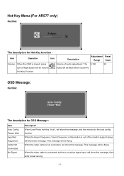
When the Hsync Frequency, Vsync Frequency or Resolution is no active signal input, will show this message, then enter power saving. - 25 - The 0-100 50 Left or Right button will be Volume Audio will be flying. This ... message. Hot-Key Menu:(For AR577 only) Outline: The description for OSD Message : Item Auto Config Please Wait Input Not Supported Cable Not Connected No Signal Description When User Press Hot-Key "Auto", will show this message, and the monitor do the auto config function. This message will show this message.
When the Hsync Frequency, Vsync Frequency or Resolution is no active signal input, will show this message, then enter power saving. - 25 - The 0-100 50 Left or Right button will be Volume Audio will be flying. This ... message. Hot-Key Menu:(For AR577 only) Outline: The description for OSD Message : Item Auto Config Please Wait Input Not Supported Cable Not Connected No Signal Description When User Press Hot-Key "Auto", will show this message, and the monitor do the auto config function. This message will show this message.

AL1715 Service Guide
Page 27
...to use a cord set by reducing power consumption when there is automatically redrawn. After the video input signal is restored, full power is restored and the display is no video input signal this monitor, following a time-out period, will automatically switch to inform the host system of its ...The communication channel is UL listed and CSA labeled. The appearance is similar to a "Screen Saver" feature except the display is no video-input signal present. The voltage rating for the power cord shall be 125 volt AC. IN ORDER FOR THIS MONITOR TO OPERATE PROPERLY, THERE MUST BE ...
...to use a cord set by reducing power consumption when there is automatically redrawn. After the video input signal is restored, full power is restored and the display is no video input signal this monitor, following a time-out period, will automatically switch to inform the host system of its ...The communication channel is UL listed and CSA labeled. The appearance is similar to a "Screen Saver" feature except the display is no video-input signal present. The voltage rating for the power cord shall be 125 volt AC. IN ORDER FOR THIS MONITOR TO OPERATE PROPERLY, THERE MUST BE ...

AL1715 Service Guide
Page 28
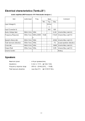
... Display OEM's". (http://www.microsoft.com/hwdev/tech/color/ColorTest.asp) Audio Technical specification (For AR577 only) General Description: Output power Total harmonic distortion Input signal sensitivity Input impedance Frequency response range Difference of color setting Color Color Coordinate Tolerance Color Coordinate Tolerance Temp. White Color Temperature White color temperature is...
... Display OEM's". (http://www.microsoft.com/hwdev/tech/color/ColorTest.asp) Audio Technical specification (For AR577 only) General Description: Output power Total harmonic distortion Input signal sensitivity Input impedance Frequency response range Difference of color setting Color Color Coordinate Tolerance Color Coordinate Tolerance Temp. White Color Temperature White color temperature is...
AL1715 Service Guide
Page 29
... Input Freq. Electrical characteristics (Tamb=25°) Audio amplifier(USE Panasonic VP-7723A Audio Analyzor. ) Item Input Voltage(V) Input Current(m A) Audio Voltage Gain Frequency Response Signal to Noise ratio Total harmonic distortion Cross talk Output Watt. s - 500 800 500m Vrms 1KHz - - 6 d B Volume Max.,load 4 Ω 500m Vrms 300Hz-20KH -10dB - +10d...
... Input Freq. Electrical characteristics (Tamb=25°) Audio amplifier(USE Panasonic VP-7723A Audio Analyzor. ) Item Input Voltage(V) Input Current(m A) Audio Voltage Gain Frequency Response Signal to Noise ratio Total harmonic distortion Cross talk Output Watt. s - 500 800 500m Vrms 1KHz - - 6 d B Volume Max.,load 4 Ω 500m Vrms 300Hz-20KH -10dB - +10d...

AL1715 Service Guide
Page 60
... 1.2W @ minimum load Total output power: 60Wmax Inverter brightness adjustment: Burst mode Protection function: auto-recovery type Interface Signals Input 1. Audio ground Ground Ground Brightness control from logical board (0V to 3.3V) ----Inverter enable signal from logical board (high active , >3V) +5Vdc supply for logical board +5Vdc supply for logical board +5Vdc...
... 1.2W @ minimum load Total output power: 60Wmax Inverter brightness adjustment: Burst mode Protection function: auto-recovery type Interface Signals Input 1. Audio ground Ground Ground Brightness control from logical board (0V to 3.3V) ----Inverter enable signal from logical board (high active , >3V) +5Vdc supply for logical board +5Vdc supply for logical board +5Vdc...

AL1715 User Guide
Page 2
... the equipment and the receiver. • Connect the equipment into an outlet on a circuit different from that to operate the equipment. Warning Use only shielded signal cables to connect I/O devices to change without prior written permission of the FCC Rules. Information in this document is subject to this manual may cause...
... the equipment and the receiver. • Connect the equipment into an outlet on a circuit different from that to operate the equipment. Warning Use only shielded signal cables to connect I/O devices to change without prior written permission of the FCC Rules. Information in this document is subject to this manual may cause...

AL1715 User Guide
Page 3
... apply pressure to the display. 4. Important Safety Instructions Please read the following occurs, immediately unplug your monitor and call an authorized technician. * Monitor to PC signal cable is frayed or damaged. * Liquid spilled into LCD Monitor or the monitor has been exposed to rain. * LCD Monitor or the case is damaged...
... apply pressure to the display. 4. Important Safety Instructions Please read the following occurs, immediately unplug your monitor and call an authorized technician. * Monitor to PC signal cable is frayed or damaged. * Liquid spilled into LCD Monitor or the monitor has been exposed to rain. * LCD Monitor or the case is damaged...

AL1715 User Guide
Page 5
... 5 mm access holes in the plastic covering as illustrated in Figure 1-4. Connect the power cord to release. The rear of the signal cable to Fig.1-3. Connect one end of the signal cable to an AC power source. 5 Figure 1-3 Figure 1-4 Figure 1-5 Figure 1-6 Make sure connections are secure. These specifications meet the VESA Flat...
... 5 mm access holes in the plastic covering as illustrated in Figure 1-4. Connect the power cord to release. The rear of the signal cable to Fig.1-3. Connect one end of the signal cable to an AC power source. 5 Figure 1-3 Figure 1-4 Figure 1-5 Figure 1-6 Make sure connections are secure. These specifications meet the VESA Flat...

AL1715 User Guide
Page 6
... Monitor complies with the VESA DPMS (version 1.0) Power Management guidelines. signal. When the LCD Monitor is in power saving mode, the monitor screen will be blank and the power LED indicator will light yellow. 6 Connecting the Audio Cable (For AL1715 m and AL1715 bm) 1. Connect the other end of the audio cable to the...
... Monitor complies with the VESA DPMS (version 1.0) Power Management guidelines. signal. When the LCD Monitor is in power saving mode, the monitor screen will be blank and the power LED indicator will light yellow. 6 Connecting the Audio Cable (For AL1715 m and AL1715 bm) 1. Connect the other end of the audio cable to the...

AL1715 User Guide
Page 11
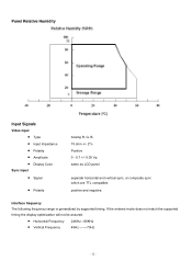
.... (typical) Vertical: -65° ~ +65° Horizontal: -80° ~ +80° 16.7M with FRC or Dithering Video Input Signal Input Impedance Polarity Amplitude Multi-mode Supported Analogue RGB 0.7Vp-p 75 Ohm ± 2% Positive, Negative 0 - 0.7 ± 0.05 Vp Horizontal Frequency...: 24 ~ 80 KHz Vertical Frequency: 49 ~ 75 Hz Control Power switch On/Off switch with LED indicator Audio (AL1715 m/AL1715 bm) Input 500mVrms Output 1W+1W OSD Brightness Contrast Horizontal Position Vertical Position Phase Clock Display Mode Setup Digital Digital Digital Digital Digital...
.... (typical) Vertical: -65° ~ +65° Horizontal: -80° ~ +80° 16.7M with FRC or Dithering Video Input Signal Input Impedance Polarity Amplitude Multi-mode Supported Analogue RGB 0.7Vp-p 75 Ohm ± 2% Positive, Negative 0 - 0.7 ± 0.05 Vp Horizontal Frequency...: 24 ~ 80 KHz Vertical Frequency: 49 ~ 75 Hz Control Power switch On/Off switch with LED indicator Audio (AL1715 m/AL1715 bm) Input 500mVrms Output 1W+1W OSD Brightness Contrast Horizontal Position Vertical Position Phase Clock Display Mode Setup Digital Digital Digital Digital Digital...
AL1715 User Guide
Page 12
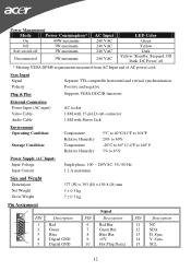
...: Standby, Suspend, Off Dark: DC Power off * Meeting VESA DPMS requirements measured from AC Input end of AC power cord. Sync Input Signal Polarity Plug & Play Separate TTL compatible horizontal and vertical synchronization Positive and negative Supports VESA DDC2B functions External Connection Power Input (AC input) Video... (W) x 393 (H) x 159.8 (D) mm 5 ± 0.5 kg 7 ± 0.5 kg Pin Assignment 6 PIN 1 11 1 2 5 15 3 4 10 5 Description Red Green Blue Digital GND Digital GND Signal PIN Description PIN Description 6 Red Rtn 11 NC 7 Green Rtn 12 SDA 8 Blue Rtn 13 H.
...: Standby, Suspend, Off Dark: DC Power off * Meeting VESA DPMS requirements measured from AC Input end of AC power cord. Sync Input Signal Polarity Plug & Play Separate TTL compatible horizontal and vertical synchronization Positive and negative Supports VESA DDC2B functions External Connection Power Input (AC input) Video... (W) x 393 (H) x 159.8 (D) mm 5 ± 0.5 kg 7 ± 0.5 kg Pin Assignment 6 PIN 1 11 1 2 5 15 3 4 10 5 Description Red Green Blue Digital GND Digital GND Signal PIN Description PIN Description 6 Red Rtn 11 NC 7 Green Rtn 12 SDA 8 Blue Rtn 13 H.

AL1715 User Guide
Page 15
... LCD Monitor's synchronous range (Horizontal: 24 ~ 80 KHz and Vertical: 49 ~ 75 Hz), the OSD will display a message "No Input Signal". 15 PROBLEM Picture is unclear and unstable The picture is no picture on again. PROBLEM There is unclear and unstable, please perform the following steps... LCD Monitor, please perform the following steps : 1. Troubleshooting This LCD Monitor has pre-adjusted using factory standard VGA timings. Also, if the signal cable is ON, all or properly, the monitor screen will display a "Out of modes supported by your PC system to LCD monitor at ...
... LCD Monitor's synchronous range (Horizontal: 24 ~ 80 KHz and Vertical: 49 ~ 75 Hz), the OSD will display a message "No Input Signal". 15 PROBLEM Picture is unclear and unstable The picture is no picture on again. PROBLEM There is unclear and unstable, please perform the following steps... LCD Monitor, please perform the following steps : 1. Troubleshooting This LCD Monitor has pre-adjusted using factory standard VGA timings. Also, if the signal cable is ON, all or properly, the monitor screen will display a "Out of modes supported by your PC system to LCD monitor at ...


