
AL1715 Service Guide
Page 4
... comliance could viold your authority to operate the equipment. Refer servicing to this equipment. WARNING: To prevent fire or chock hazard, do not expose the monitor to correct the interference by turning the equipment off and on a circuit different from that this product meets the ENERGY STAR® guidelines for help...: this equipment has been tested and found to comply with the instructions, may cause harmful interference to radio communications. These limits are present inside the monitor. Connect the equipment into an outlet on , the user is connected. 4.
... comliance could viold your authority to operate the equipment. Refer servicing to this equipment. WARNING: To prevent fire or chock hazard, do not expose the monitor to correct the interference by turning the equipment off and on a circuit different from that this product meets the ENERGY STAR® guidelines for help...: this equipment has been tested and found to comply with the instructions, may cause harmful interference to radio communications. These limits are present inside the monitor. Connect the equipment into an outlet on , the user is connected. 4.
AL1715 Service Guide
Page 5
...openings in a wet basement. To ensure reliable operation of the cabinet area provided for long periods of power source indicated on the monitor. Do not place the monitor near the equipment and shall be easily accessible. - 5 - If you are not blocked or covered. Do not defeat the ...with UL listed computers which have an electrician install the correct outlet, or use a mounting kit approved by the manufacture or sold with the monitor. opening or removing covers can injure a person and cause serious damage to your home, consult your outlet does not accommodate the three-wire plug...
...openings in a wet basement. To ensure reliable operation of the cabinet area provided for long periods of power source indicated on the monitor. Do not place the monitor near the equipment and shall be easily accessible. - 5 - If you are not blocked or covered. Do not defeat the ...with UL listed computers which have an electrician install the correct outlet, or use a mounting kit approved by the manufacture or sold with the monitor. opening or removing covers can injure a person and cause serious damage to your home, consult your outlet does not accommodate the three-wire plug...

AL1715 Service Guide
Page 6
... following symptoms are normal with LCD monitor and do not indicate a problem. In this case, the screen is displayed for hours. - 6 - You may flicker during initial use . Turn off the Power Switch ...
... following symptoms are normal with LCD monitor and do not indicate a problem. In this case, the screen is displayed for hours. - 6 - You may flicker during initial use . Turn off the Power Switch ...

AL1715 Service Guide
Page 7
Table of contents Chapter 1 Monitor Feature 8 Chapter 2 Operating Instruction 22 Chapter 3 Machine Disassembly and Replacement 30 Chapter 4 Troubleshooting 40 Chapter 5 Connector Information 44 Chapter 6 FRU List 45 Chapter 7 Schematic Diagram 65 - 7 -
Table of contents Chapter 1 Monitor Feature 8 Chapter 2 Operating Instruction 22 Chapter 3 Machine Disassembly and Replacement 30 Chapter 4 Troubleshooting 40 Chapter 5 Connector Information 44 Chapter 6 FRU List 45 Chapter 7 Schematic Diagram 65 - 7 -

AL1715 Service Guide
Page 8
...of speakers. DDC2B NO NO No Not support Yes / No Option Description The LCD monitor is also a space saving design, allowing more . It is designed with no radiation. Monitor Feature INTRODUCTION Chapter 1 Scope This specification defines the requirements for analog input DSUB Separate...supports VESA DPMS power management and plug & play function. This will alleviate the growing health concerns. This monitor can be directly connected to the traditional CRT monitor, it consumes less power and gets less weight in stereo audio amplifier with volume control to provide a ...
...of speakers. DDC2B NO NO No Not support Yes / No Option Description The LCD monitor is also a space saving design, allowing more . It is designed with no radiation. Monitor Feature INTRODUCTION Chapter 1 Scope This specification defines the requirements for analog input DSUB Separate...supports VESA DPMS power management and plug & play function. This will alleviate the growing health concerns. This monitor can be directly connected to the traditional CRT monitor, it consumes less power and gets less weight in stereo audio amplifier with volume control to provide a ...

AL1715 Service Guide
Page 9
... of LCD panel Warrn up time All specifications : 30 minutes Fully functional : 5 seconds Measuring Equipment : Chroma 2250 signal generator or equivalent, directly Connected to the monitor under the following conditions, unless otherwise specified.
... of LCD panel Warrn up time All specifications : 30 minutes Fully functional : 5 seconds Measuring Equipment : Chroma 2250 signal generator or equivalent, directly Connected to the monitor under the following conditions, unless otherwise specified.

AL1715 Service Guide
Page 10
LCD monitor General specification Panel Type: 17 " active matrix color TFT LCD 1). Hydis HT17E12-200 Display size: Display mode: Pixel pitch: Display Dot: Pixel Clock: Contrast ratio: &#...
LCD monitor General specification Panel Type: 17 " active matrix color TFT LCD 1). Hydis HT17E12-200 Display size: Display mode: Pixel pitch: Display Dot: Pixel Clock: Contrast ratio: &#...
AL1715 Service Guide
Page 14
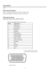
... 7 GREEN GROUND 8 BLUE GROUND 9 PC5V (+5V DDC) 10 CABLE DETECTION 11 GROUND 12 SDA 13 H.SYNC 14 V.SYNC 15 SCL Color of the monitor. 85Hz refresh rate Support Monitor should display "Out of Range" warning menu at this mode. Video input Connector Analog Video input Connector: 15pins mini D-Sub Table 2.4.5. Support Modes... modes to accommodate the above mode and other video modes within the frequency range of plastic parts: Blue (PC99) 5 10 15 D-sub connector 1 6 11 - 14 - Monitor should display 85Hz refresh rate mode as emergency mode.
... 7 GREEN GROUND 8 BLUE GROUND 9 PC5V (+5V DDC) 10 CABLE DETECTION 11 GROUND 12 SDA 13 H.SYNC 14 V.SYNC 15 SCL Color of the monitor. 85Hz refresh rate Support Monitor should display "Out of Range" warning menu at this mode. Video input Connector Analog Video input Connector: 15pins mini D-Sub Table 2.4.5. Support Modes... modes to accommodate the above mode and other video modes within the frequency range of plastic parts: Blue (PC99) 5 10 15 D-sub connector 1 6 11 - 14 - Monitor should display 85Hz refresh rate mode as emergency mode.

AL1715 Service Guide
Page 15
The inverter board will provide thr 12V DC-power to inverter/ power board. The Adapter will drive the backlight of panel and the DC-DC conversion. Power board (include: AC/DC,inverter) - 15 - Monitor Block Diagram The LCD monitor will contain an main board, an inverter/ power board, key board and internal adapter which house the flat panel control logic, brightness control logic and DDC.
The inverter board will provide thr 12V DC-power to inverter/ power board. The Adapter will drive the backlight of panel and the DC-DC conversion. Power board (include: AC/DC,inverter) - 15 - Monitor Block Diagram The LCD monitor will contain an main board, an inverter/ power board, key board and internal adapter which house the flat panel control logic, brightness control logic and DDC.
AL1715 Service Guide
Page 20
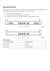
Connect the video cable from the monitor to turn the monitor on the monitor position. The other control buttons are located at front panel of the monitor. By changing these settings, the picture can be connected. The power cord should be adjusted to your personal preferences. General Instructions Press the power button to turn on or off. AR577 External Controls 1 Auto Adjust Key/Exit 2 / Volume 4 MENU/ENTER 5 LED 6 / Power Key AR578 - 20 - The power indicator will light up. Press the power button to the video card.
Connect the video cable from the monitor to turn the monitor on the monitor position. The other control buttons are located at front panel of the monitor. By changing these settings, the picture can be connected. The power cord should be adjusted to your personal preferences. General Instructions Press the power button to turn on or off. AR577 External Controls 1 Auto Adjust Key/Exit 2 / Volume 4 MENU/ENTER 5 LED 6 / Power Key AR578 - 20 - The power indicator will light up. Press the power button to the video card.

AL1715 Service Guide
Page 21
... other end of the signal cable to the VGA port on your computer. Make sure connections are secure. Connect the power cord to the LCD Monitor. System Installation Connecting the Display Power off your PC's audio card or to the front panel's "AUDIO OUT" jack of the signal cable to the... LCD Monitor's VGA port. Connecting the AC Power Connect the power cord to an AC power source. Connect one end of your PC. Connecting the Audio Cable...
... other end of the signal cable to the VGA port on your computer. Make sure connections are secure. Connect the power cord to the LCD Monitor. System Installation Connecting the Display Power off your PC's audio card or to the front panel's "AUDIO OUT" jack of the signal cable to the... LCD Monitor's VGA port. Connecting the AC Power Connect the power cord to an AC power source. Connect one end of your PC. Connecting the Audio Cable...
AL1715 Service Guide
Page 22
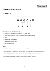
... (Function select). 5. Press button 4 (plus +),(minus -) and 1 (power) together 2 seconds at the same time can activate "Auto Adjustment" immediately. 3. Operating Instructions CONTROLS Chapter 2 Control panel (monitor front panel) 1. When into Burning mode press 5 (menus), 1 (power) together 2 second at the same time can activate "Volume Adjustment". 2. Power ON/OFF switch, push to...
... (Function select). 5. Press button 4 (plus +),(minus -) and 1 (power) together 2 seconds at the same time can activate "Auto Adjustment" immediately. 3. Operating Instructions CONTROLS Chapter 2 Control panel (monitor front panel) 1. When into Burning mode press 5 (menus), 1 (power) together 2 second at the same time can activate "Volume Adjustment". 2. Power ON/OFF switch, push to...
AL1715 Service Guide
Page 25
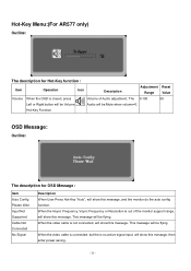
... Cable Not Connected No Signal Description When User Press Hot-Key "Auto", will be flying. When the video cable is closed, press Volume of the monitor support range, will show this message. Hot-Key Function OSD Message: Outline: The description for Hot-Key function : Item Operation Icon Description Adjustment Reset Range...
... Cable Not Connected No Signal Description When User Press Hot-Key "Auto", will be flying. When the video cable is closed, press Volume of the monitor support range, will show this message. Hot-Key Function OSD Message: Outline: The description for Hot-Key function : Item Operation Icon Description Adjustment Reset Range...

AL1715 Service Guide
Page 26
.... -color temp default preset No. - 26 - This function shall be located in the center. Item of auto adjust is power on hardware. LOGO: When the monitor is depends on , the LOGO will be showed in 3.
.... -color temp default preset No. - 26 - This function shall be located in the center. Item of auto adjust is power on hardware. LOGO: When the monitor is depends on , the LOGO will be showed in 3.

AL1715 Service Guide
Page 27
... (EPA) and The Swedish Confederation Employees (NUTEK). The display is restored by reducing power consumption when there is no video input signal this monitor, following a time-out period, will automatically switch to power outlet of a minimum No. 18 AWG, type SJT or SVT three conductors ...computer: Please use VDE 0602, 0625, 0821 approval power cord in two levels, DDC2B. Plug and play Plug & play DDC2B feature This monitor is equipped with VESA DDC2B capabilities according to a "Screen Saver" feature except the display is completely off. The DDC2Bis a bidirectional data channel...
... (EPA) and The Swedish Confederation Employees (NUTEK). The display is restored by reducing power consumption when there is no video input signal this monitor, following a time-out period, will automatically switch to power outlet of a minimum No. 18 AWG, type SJT or SVT three conductors ...computer: Please use VDE 0602, 0625, 0821 approval power cord in two levels, DDC2B. Plug and play Plug & play DDC2B feature This monitor is equipped with VESA DDC2B capabilities according to a "Screen Saver" feature except the display is completely off. The DDC2Bis a bidirectional data channel...

AL1715 Service Guide
Page 35
To reverse the monitor. Assemble the power board onto chassis. AR577 AR578 35 Connect speaker wires on VK board. (For AR577 only) Connect the bezel with monitor.
To reverse the monitor. Assemble the power board onto chassis. AR577 AR578 35 Connect speaker wires on VK board. (For AR577 only) Connect the bezel with monitor.

AL1715 Service Guide
Page 38
Check it. Connect the audio line on power board. (For AR577 only) Firmly secure the line and chassis with monitor. 38 AR577 AR578 Put the EMI cover on EMI cover with 4 screws. Put the screws on monitor..
Check it. Connect the audio line on power board. (For AR577 only) Firmly secure the line and chassis with monitor. 38 AR577 AR578 Put the EMI cover on EMI cover with 4 screws. Put the screws on monitor..

AL1715 Service Guide
Page 39
Firmly secure the back cover with 4 screws. 1. Firmly secure the neck bracket with 4 screws. 1. Put the screws on EMI cover with 4 screws. Assemble the neck bracket onto neck. 2. Firmly secure the neck with monitor. 1. Assemble the neck with monitor 39 Assemble the base with back cover. 2. Firmly secure the hinge with neck. 2. Connect the hinge with 3 screws. 1. Connect the back cover with monitor. 2.
Firmly secure the back cover with 4 screws. 1. Firmly secure the neck bracket with 4 screws. 1. Put the screws on EMI cover with 4 screws. Assemble the neck bracket onto neck. 2. Firmly secure the neck with monitor. 1. Assemble the neck with monitor 39 Assemble the base with back cover. 2. Firmly secure the hinge with neck. 2. Connect the hinge with 3 screws. 1. Connect the back cover with monitor. 2.
AL1715 Service Guide
Page 64
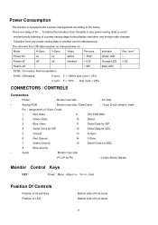
.... F < 10Hz duty cycle > 25% CONNECTORS / CONTROLS Connectors - V-Sync. F < 10KHz duty cycle > 25% V sync. Power Consumption The monitor is a delay of a power saving stage during display resolution and timing mode changes. The recovery from On-state to any power saving state to another...Inlet - Transition from any power saving state to the below. Analog RGB : Monitor rear side / Data Cable : 15-pin D-sub female / male Pin - Audio : Monitor rear side : -PC I/P for PC : 3.5mm Stereo female Monitor Control Keys KEY : Power , Menu , Adjust +/- , Vol +/-, Auto...
.... F < 10Hz duty cycle > 25% CONNECTORS / CONTROLS Connectors - V-Sync. F < 10KHz duty cycle > 25% V sync. Power Consumption The monitor is a delay of a power saving stage during display resolution and timing mode changes. The recovery from On-state to any power saving state to another...Inlet - Transition from any power saving state to the below. Analog RGB : Monitor rear side / Data Cable : 15-pin D-sub female / male Pin - Audio : Monitor rear side : -PC I/P for PC : 3.5mm Stereo female Monitor Control Keys KEY : Power , Menu , Adjust +/- , Vol +/-, Auto...

AL1715 User Guide
Page 1
... DOC Notice ...2 Important Safety Instructions...3 Chapter 1 Installation ...4 Unpacking...4 Connecting the LCD Monitor and Base 4 Viewing Angle Adjustment ...4 Detaching LCD Monitor from Its Stand 5 Interface for Arm Applications ...5 Connecting the Display...5 Connecting the AC Power ...5 Connecting the Audio Cable (For AL1715 m and AL1715 bm 6 Power Management System...6 Chapter 2 Display Controls 7 General Instructions...7 Front Panel Control...
... DOC Notice ...2 Important Safety Instructions...3 Chapter 1 Installation ...4 Unpacking...4 Connecting the LCD Monitor and Base 4 Viewing Angle Adjustment ...4 Detaching LCD Monitor from Its Stand 5 Interface for Arm Applications ...5 Connecting the Display...5 Connecting the AC Power ...5 Connecting the Audio Cable (For AL1715 m and AL1715 bm 6 Power Management System...6 Chapter 2 Display Controls 7 General Instructions...7 Front Panel Control...


