

AC 501 User Guide
Page 2
Table of Contents Important Safety Instructions 3 Federal Communications Commission 4 Connecting the Monitor and Swivel Base 5 Removing the Monitor and Swivel Base 5 Introduction...6 Installation...7 User Controls...8 Adjusting the Brightness and Contrast 9 OSD Function Description 9 OSD Icon Summary 10 Specification ...11 Troubleshooting 12 2
Table of Contents Important Safety Instructions 3 Federal Communications Commission 4 Connecting the Monitor and Swivel Base 5 Removing the Monitor and Swivel Base 5 Introduction...6 Installation...7 User Controls...8 Adjusting the Brightness and Contrast 9 OSD Function Description 9 OSD Icon Summary 10 Specification ...11 Troubleshooting 12 2

AC 501 User Guide
Page 3
...these instructions thoroughly. 2. Do not use . 3. Use a clean dampened cloth in such a way nobody can trip over or dropping can harm the monitor and cause injuries. Protect the device against overheating. 8. The wall socket must be laid in stead. 4. The power cable must be easily accessible. ... repairs to guarantee the device's performance and reliability. 18. The device shows obvious signs of the main power supply. 9. Please contact your monitor. 7. The power socket must be disconnected from the main supply, and be used for future use any improvement with the aid of this ...
...these instructions thoroughly. 2. Do not use . 3. Use a clean dampened cloth in such a way nobody can trip over or dropping can harm the monitor and cause injuries. Protect the device against overheating. 8. The wall socket must be laid in stead. 4. The power cable must be easily accessible. ... repairs to guarantee the device's performance and reliability. 18. The device shows obvious signs of the main power supply. 9. Please contact your monitor. 7. The power socket must be disconnected from the main supply, and be used for future use any improvement with the aid of this ...

AC 501 User Guide
Page 5
... tabs of the swivel base with its tube down . Place the monitor with its tube down on the front panel when you place the monitor with the slots in the bottom of the monitor 4. Insert the tabs into place. Removing the Monitor and Swivel Base If you hear the spring lock click into the... slots of the monitor. 3. Now slowly slide the swivel base toward the front of the monitor till you need to the control knobs and LED indicators on a stable surface. 2. NOTE: Special attention should be paid to remove the swivel base, push...
... tabs of the swivel base with its tube down . Place the monitor with its tube down on the front panel when you place the monitor with the slots in the bottom of the monitor 4. Insert the tabs into place. Removing the Monitor and Swivel Base If you hear the spring lock click into the... slots of the monitor. 3. Now slowly slide the swivel base toward the front of the monitor till you need to the control knobs and LED indicators on a stable surface. 2. NOTE: Special attention should be paid to remove the swivel base, push...

AC 501 User Guide
Page 6
... Please contact your dealer or nearest service centers if any of the screen image. Using state-of this monitor supports a 1280 x 1024 resolution. Features 15-inch monitor with a large, viewable screen for reduced power consumption. Energy Star compliant for comfortable viewing. The on ...your purchase of -the-art electronics, this new high performance 15" Monitor. OSD user controls for easy and accurate adjustment of the above items is missing or damaged. 6 Introduction Congratulations on -screen display...
... Please contact your dealer or nearest service centers if any of the screen image. Using state-of this monitor supports a 1280 x 1024 resolution. Features 15-inch monitor with a large, viewable screen for reduced power consumption. Energy Star compliant for comfortable viewing. The on ...your purchase of -the-art electronics, this new high performance 15" Monitor. OSD user controls for easy and accurate adjustment of the above items is missing or damaged. 6 Introduction Congratulations on -screen display...
AC 501 User Guide
Page 7
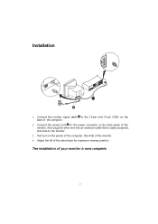
Adjust the tilt of the monitor, then plug the other end into an electrical outlet that of the computer. 2. Connect the power cord to the 15-pin mini D-sub (VGA) on the back of the monitor. 4. Connect the monitor signal cable 1 to the power connector on the power of the computer, then that is now complete. 7 First turn on the back panel of the swivel base for maximum viewing comfort. Installation 1. The installation of your monitor is easily accessible, and close to the monitor. 3.
Adjust the tilt of the monitor, then plug the other end into an electrical outlet that of the computer. 2. Connect the power cord to the 15-pin mini D-sub (VGA) on the back of the monitor. 4. Connect the monitor signal cable 1 to the power connector on the power of the computer, then that is now complete. 7 First turn on the back panel of the swivel base for maximum viewing comfort. Installation 1. The installation of your monitor is easily accessible, and close to the monitor. 3.
AC 501 User Guide
Page 8
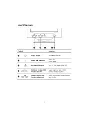
Sleep Turn the OSD Display ON or OFF Brightness Control/ OSD Adjust Brightness level or OSD Function selection Function selection Control Contrast Control/OSD Function adjustment Adjust Contract level or OSD Function Level Control 8 User Controls Control Power Switch Power LED Indicator OSD ON/OFF Control Function Turns the monitor on Green- On Amber-
Sleep Turn the OSD Display ON or OFF Brightness Control/ OSD Adjust Brightness level or OSD Function selection Function selection Control Contrast Control/OSD Function adjustment Adjust Contract level or OSD Function Level Control 8 User Controls Control Power Switch Power LED Indicator OSD ON/OFF Control Function Turns the monitor on Green- On Amber-

AC 501 User Guide
Page 12
... is connected properly to the video adapter port on the back of the PC. Move any electrical devices that can cause interference away from the monitor. (Note: Please refers to the FCC statement at the beginning of the PC. Problem: No display appears on . Make sure that the video cable...service center. Check to their dimmest position. Problem: Display image is bouncing or in the "On" position. Problem: Power LED is not lit when monitor is in a wave pattern. Make sure that the brightness and contrast controls are not turned to make sure that the computer switch is powered on...
... is connected properly to the video adapter port on the back of the PC. Move any electrical devices that can cause interference away from the monitor. (Note: Please refers to the FCC statement at the beginning of the PC. Problem: No display appears on . Make sure that the video cable...service center. Check to their dimmest position. Problem: Display image is bouncing or in the "On" position. Problem: Power LED is not lit when monitor is in a wave pattern. Make sure that the brightness and contrast controls are not turned to make sure that the computer switch is powered on...

AC501 Monitor Service Guide
Page 3
... pattern, adjust both horizontal and vertical OSD's size control to get a DC 13.0±0.1V to proceed al ignment. CRT faces to east direction, connects monitor and generator, warm up 30 minut es at least before to be less than 1000 gamma, the magnitude of t he vertical magnetic field component is...
... pattern, adjust both horizontal and vertical OSD's size control to get a DC 13.0±0.1V to proceed al ignment. CRT faces to east direction, connects monitor and generator, warm up 30 minut es at least before to be less than 1000 gamma, the magnitude of t he vertical magnetic field component is...

AC501 Monitor Service Guide
Page 5
...center can't be adjust to get properly, P801 may sometime be clear, legible and uniform, if not, repeat stape 2.3.2.1 to get into off monitor power and plug in mode. B-13. B-17. X-ray protection test B-20. Burn-in engineering specification. B-23. Mi sconvergence alignment B-14.... B-16. Preset modes alignment B-15. Adjust H-size/ H-phase/V-size/V-center/ pincushion/trapezoid control s.... Turn off the monitor power and unplug P103 then disconnect H or V sync, turn on the power again to get into factory mode. Turn off power, disconnect I/O ...
...center can't be adjust to get properly, P801 may sometime be clear, legible and uniform, if not, repeat stape 2.3.2.1 to get into off monitor power and plug in mode. B-13. B-17. X-ray protection test B-20. Burn-in engineering specification. B-23. Mi sconvergence alignment B-14.... B-16. Preset modes alignment B-15. Adjust H-size/ H-phase/V-size/V-center/ pincushion/trapezoid control s.... Turn off the monitor power and unplug P103 then disconnect H or V sync, turn on the power again to get into factory mode. Turn off power, disconnect I/O ...
AC501 Monitor Service Guide
Page 14
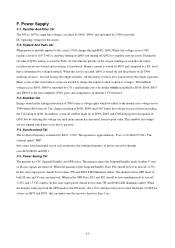
... Q970 and R971, that comes from exceeding the Vds rating of power circuit by R907 and compared to the output capacitors. Power Saving Ckt The monitor has ON, Suspend/Standby and OFF states. When this state, input power should be less than 5W and D960 LED illuminate amber. F-3. F.... F-4. D904, and smoothed by R914, R916, R917 and VR901 to the error amplifier (U901 pin2) and compared to turn off . When the monitor wakes up from its peak value. Flyback And Pwm Ckt When power is initially applied to the circuit, C909 charges through cross t he voltage across...
... Q970 and R971, that comes from exceeding the Vds rating of power circuit by R907 and compared to the output capacitors. Power Saving Ckt The monitor has ON, Suspend/Standby and OFF states. When this state, input power should be less than 5W and D960 LED illuminate amber. F-3. F.... F-4. D904, and smoothed by R914, R916, R917 and VR901 to the error amplifier (U901 pin2) and compared to turn off . When the monitor wakes up from its peak value. Flyback And Pwm Ckt When power is initially applied to the circuit, C909 charges through cross t he voltage across...

AC501 Monitor Service Guide
Page 20
Digit Control Digit control circuit includes micro processor U2(UMC6861), EEPROM IC(24LC04). The u-P will be difference SW1/SW2 in difference horizontal frequency, Table 5.1 is the switching table: SW1 SW2 Hf < 40 KHz L L Hf < 58.5 KHz L H Hf > 58.5 KHz H H 20 With t he functions and all the functions of the monitor. There will mute the video signal whenever the mode changes. K. User can control t he program, u-P control all the functions shows on the OSD.
Digit Control Digit control circuit includes micro processor U2(UMC6861), EEPROM IC(24LC04). The u-P will be difference SW1/SW2 in difference horizontal frequency, Table 5.1 is the switching table: SW1 SW2 Hf < 40 KHz L L Hf < 58.5 KHz L H Hf > 58.5 KHz H H 20 With t he functions and all the functions of the monitor. There will mute the video signal whenever the mode changes. K. User can control t he program, u-P control all the functions shows on the OSD.

AC501 Monitor Service Guide
Page 23
No Check VR901, D941, A942, Q943 No Check D940, Q940, R945, D951 No Check D942, C946 Combine with No monitor check operating frequency? Check and repaor Q902, Q903, U901, D908, R931 D909, R908 Is 13V in spec? Is 7.5V in spec? Power Supply Check S ta rt Check Yes fuse open Check and repaor EMI Filter and Q901, I/P Rectifer R909, U901, R907 Is Q901 VDS No waveform normally? Is 60V voltage correct? TROUBLE SHOOTING A. OK S to p Check and repair R919, R912, R918, C912 23 4.
No Check VR901, D941, A942, Q943 No Check D940, Q940, R945, D951 No Check D942, C946 Combine with No monitor check operating frequency? Check and repaor Q902, Q903, U901, D908, R931 D909, R908 Is 13V in spec? Is 7.5V in spec? Power Supply Check S ta rt Check Yes fuse open Check and repaor EMI Filter and Q901, I/P Rectifer R909, U901, R907 Is Q901 VDS No waveform normally? Is 60V voltage correct? TROUBLE SHOOTING A. OK S to p Check and repair R919, R912, R918, C912 23 4.

AC501 Monitor Service Guide
Page 24
T Check power supply circuit Check power supply c ir c u it Check U401 No No Check U401 pin7 output sequare wave from Ye s Check Q506 Ye s No C he ck F. B . B. Ye s Check HEATER voltage= +6.3VDC G1 = 50-80 VDC G2 = 500-600 VDC Ye s Check CRT Check AC Ye s power input No Check Q801 collector voltage about 80-155V Ye s C he ck F. T pin 3, voltage about 1200 Vpp Ye s C he ck F. T 24 Monitor Check Flow Chart B-1 No Raster No raster Check power No indecator lighted Ye s Check contrast & brightness control adjust to MAX. B . B .
T Check power supply circuit Check power supply c ir c u it Check U401 No No Check U401 pin7 output sequare wave from Ye s Check Q506 Ye s No C he ck F. B . B. Ye s Check HEATER voltage= +6.3VDC G1 = 50-80 VDC G2 = 500-600 VDC Ye s Check CRT Check AC Ye s power input No Check Q801 collector voltage about 80-155V Ye s C he ck F. T pin 3, voltage about 1200 Vpp Ye s C he ck F. T 24 Monitor Check Flow Chart B-1 No Raster No raster Check power No indecator lighted Ye s Check contrast & brightness control adjust to MAX. B . B .

AC501 Monitor Service Guide
Page 39
... LED LENS(P554) 4RUBBER WASHER 1SCREW 4TAPPING SCREW 4SCREW 1PACKING ABO 1RATING NP-W/W 1CARTON 1USER'S MANUAL 2LABEL 1STATIC LABEL 1PE BAG (MONITOR) 1SWIVEL BASE&BALL ASS 1EPS FOAM(L) 1EPS FOAM(R) 1POWER CORD SET 1MECHANICAL PARTS 1BACK COVER(NONE USB) 1SPONGE 4TAPPING SCREW Line ... 30 5CB0470346T4 31 5CB10002M0T4 32 5CB1000342T1 33 5CC0300211T4 34 5CC0330111T0 35 5CC0470011T1 36 5CC0750225T9 37 5CC1000111T2 38 5CC1000211T8 39 5CC1001011T1 Model AC501 (P557 Usage Description 1DIS ABO 1CRT & YOKE ASSY, 15C 1CRT&YOKE 1COIL SET 1DEGAUSSING COIL 1H-CON SET 1LOCKING ...
... LED LENS(P554) 4RUBBER WASHER 1SCREW 4TAPPING SCREW 4SCREW 1PACKING ABO 1RATING NP-W/W 1CARTON 1USER'S MANUAL 2LABEL 1STATIC LABEL 1PE BAG (MONITOR) 1SWIVEL BASE&BALL ASS 1EPS FOAM(L) 1EPS FOAM(R) 1POWER CORD SET 1MECHANICAL PARTS 1BACK COVER(NONE USB) 1SPONGE 4TAPPING SCREW Line ... 30 5CB0470346T4 31 5CB10002M0T4 32 5CB1000342T1 33 5CC0300211T4 34 5CC0330111T0 35 5CC0470011T1 36 5CC0750225T9 37 5CC1000111T2 38 5CC1000211T8 39 5CC1001011T1 Model AC501 (P557 Usage Description 1DIS ABO 1CRT & YOKE ASSY, 15C 1CRT&YOKE 1COIL SET 1DEGAUSSING COIL 1H-CON SET 1LOCKING ...

AC501 Monitor Service Guide
Page 49
... LED LENS(P554) 4RUBBER WASHER 1SCREW 4TAPPING SCREW 4SCREW 1PACKING ABO 1RATING NP-W/W 1CARTON 1USER'S MANUAL 2LABEL 1STATIC LABEL 1PE BAG (MONITOR) 1SWIVEL BASE&BALL ASS 1EPS FOAM(L) 1EPS FOAM(R) 1PWR CORD 1MECHANICAL PARTS 1BACK COVER(NONE USB) 1SPONGE 4TAPPING SCREW Line Level ...15 5BC1FR1040T0 16 5BC4HZ2720T5 17 5BC4HZ5C10T8 18 5BCSN58171T0 19 5CA001A601T8 20 5CA001B631T8 21 5CA001CPK0T8 22 5CA010CCM0T6 23 5CA047ECK0T0 24 5CA082F601T6 Model AC501 (P557 Usage Description 1DIS ABO 1CRT & YOKE ASSY, 15C 1CRT&YOKE 1COIL SET 1DEGAUSSING COIL 1H-CON SET 1LOCKING...
... LED LENS(P554) 4RUBBER WASHER 1SCREW 4TAPPING SCREW 4SCREW 1PACKING ABO 1RATING NP-W/W 1CARTON 1USER'S MANUAL 2LABEL 1STATIC LABEL 1PE BAG (MONITOR) 1SWIVEL BASE&BALL ASS 1EPS FOAM(L) 1EPS FOAM(R) 1PWR CORD 1MECHANICAL PARTS 1BACK COVER(NONE USB) 1SPONGE 4TAPPING SCREW Line Level ...15 5BC1FR1040T0 16 5BC4HZ2720T5 17 5BC4HZ5C10T8 18 5BCSN58171T0 19 5CA001A601T8 20 5CA001B631T8 21 5CA001CPK0T8 22 5CA010CCM0T6 23 5CA047ECK0T0 24 5CA082F601T6 Model AC501 (P557 Usage Description 1DIS ABO 1CRT & YOKE ASSY, 15C 1CRT&YOKE 1COIL SET 1DEGAUSSING COIL 1H-CON SET 1LOCKING...

AC501 Monitor Service Guide
Page 54
...(P554) 4RUBBER WASHER 1SCREW 4TAPPING SCREW 4SCREW 1PACKING ABO 1RATING NP-W/W 1CARTON 1USER'S MANUAL 2LABEL 1STATIC LABEL 1PE BAG (MONITOR) 1SWIVEL BASE&BALL ASS 1EPS FOAM(L) 1EPS FOAM(R) 1MECHANICAL PARTS 1BACK COVER(NONE USB) 1SPONGE 4TAPPING SCREW Line Level Part...3KA000001ZZ4 8 251A03600009 9 3452A1800001 10 4442A1800001 11 5BB30945P1T5 12 5BBX042000T9 13 5BC101SS82T2 14 5BC11N4148T8 15 5BC1FR1040T0 16 5BC4HZ2720T5 17 5BC4HZ5C10T8 Model AC501 (P557 Usage Description 1DIS ABO 1CRT & YOKE ASSY, 15C 1CRT&YOKE 1COIL SET 1DEGAUSSING COIL 1H-CON SET 1LOCKING CABLE...
...(P554) 4RUBBER WASHER 1SCREW 4TAPPING SCREW 4SCREW 1PACKING ABO 1RATING NP-W/W 1CARTON 1USER'S MANUAL 2LABEL 1STATIC LABEL 1PE BAG (MONITOR) 1SWIVEL BASE&BALL ASS 1EPS FOAM(L) 1EPS FOAM(R) 1MECHANICAL PARTS 1BACK COVER(NONE USB) 1SPONGE 4TAPPING SCREW Line Level Part...3KA000001ZZ4 8 251A03600009 9 3452A1800001 10 4442A1800001 11 5BB30945P1T5 12 5BBX042000T9 13 5BC101SS82T2 14 5BC11N4148T8 15 5BC1FR1040T0 16 5BC4HZ2720T5 17 5BC4HZ5C10T8 Model AC501 (P557 Usage Description 1DIS ABO 1CRT & YOKE ASSY, 15C 1CRT&YOKE 1COIL SET 1DEGAUSSING COIL 1H-CON SET 1LOCKING CABLE...

AC501 Monitor Service Guide
Page 59
...(P554) 4RUBBER WASHER 1SCREW 4TAPPING SCREW 4SCREW 1PACKING ABO 1RATING NP-W/W 1CARTON 1USER'S MANUAL 2LABEL 1STATIC LABEL 1PE BAG (MONITOR) 1SWIVEL BASE&BALL ASS 1EPS FOAM(L) 1EPS FOAM(R) 1MECHANICAL PARTS 1BACK COVER(NONE USB) 1SPONGE 4TAPPING SCREW Line Level Part... 1 1MP557G01008 2 251A03500021 3 3AC500025510 4 3CL700001900 5 3CLA4M100106 6 3DC020132501 7 3KA000001ZZ4 8 251A03600009 9 3452A1800001 10 4442A1800001 Model AC501 (P557 Usage Description 1DIS ABO 1CRT & YOKE ASSY, 15C 1CRT&YOKE 1COIL SET 1DEGAUSSING COIL 1H-CON SET 1LOCKING CABLE TIE ...
...(P554) 4RUBBER WASHER 1SCREW 4TAPPING SCREW 4SCREW 1PACKING ABO 1RATING NP-W/W 1CARTON 1USER'S MANUAL 2LABEL 1STATIC LABEL 1PE BAG (MONITOR) 1SWIVEL BASE&BALL ASS 1EPS FOAM(L) 1EPS FOAM(R) 1MECHANICAL PARTS 1BACK COVER(NONE USB) 1SPONGE 4TAPPING SCREW Line Level Part... 1 1MP557G01008 2 251A03500021 3 3AC500025510 4 3CL700001900 5 3CLA4M100106 6 3DC020132501 7 3KA000001ZZ4 8 251A03600009 9 3452A1800001 10 4442A1800001 Model AC501 (P557 Usage Description 1DIS ABO 1CRT & YOKE ASSY, 15C 1CRT&YOKE 1COIL SET 1DEGAUSSING COIL 1H-CON SET 1LOCKING CABLE TIE ...

AC501 Monitor Service Guide
Page 64
... 1POWER LED LENS(P554) 4RUBBER WASHER 1SCREW 4TAPPING SCREW 4SCREW 1PACKING ABO 1RATING NP-W/W 1CARTON 1USER'S MANUAL 2LABEL 1STATIC LABEL 1PE BAG (MONITOR) 1SWIVEL BASE&BALL ASS 1EPS FOAM(L) 1EPS FOAM(R) 1POWER CORD SET 1MECHANICAL PARTS 1BACK COVER(NONE USB) 1SPONGE 4TAPPING SCREW Line Level Part... 1 1MP557G04001 2 251A03500006 Model AC501 (P557) Usage Description 1DIS ABO 1CRT & YOKE ASSY, 15C 64 ER306 DO-201AD UF5402G DO-201AD P PG5406-F17 DO-201A LA89W/YSG...
... 1POWER LED LENS(P554) 4RUBBER WASHER 1SCREW 4TAPPING SCREW 4SCREW 1PACKING ABO 1RATING NP-W/W 1CARTON 1USER'S MANUAL 2LABEL 1STATIC LABEL 1PE BAG (MONITOR) 1SWIVEL BASE&BALL ASS 1EPS FOAM(L) 1EPS FOAM(R) 1POWER CORD SET 1MECHANICAL PARTS 1BACK COVER(NONE USB) 1SPONGE 4TAPPING SCREW Line Level Part... 1 1MP557G04001 2 251A03500006 Model AC501 (P557) Usage Description 1DIS ABO 1CRT & YOKE ASSY, 15C 64 ER306 DO-201AD UF5402G DO-201AD P PG5406-F17 DO-201A LA89W/YSG...

AC501 Monitor Service Guide
Page 69
... WASHER 1SCREW 4TAPPING SCREW 4SCREW 1PACKING ABO 1RATING NP-W/W 1CARTON 1USER'S MANUAL 1NOTICE SHEET 1ENERGY STAR LABEL 2TCO 95 LABEL 1TCO 95 LABEL 1PE BAG (MONITOR) 1SWIVEL BASE&BALL ASS 69 TPB-3+10R-MC (ADD TPB-3+8C-MC TPB-3+6CF-MC(EX.LO TPB-4+8C-MC 1M 1007 #22 BLK (T 4.3DX90X10T...
... WASHER 1SCREW 4TAPPING SCREW 4SCREW 1PACKING ABO 1RATING NP-W/W 1CARTON 1USER'S MANUAL 1NOTICE SHEET 1ENERGY STAR LABEL 2TCO 95 LABEL 1TCO 95 LABEL 1PE BAG (MONITOR) 1SWIVEL BASE&BALL ASS 69 TPB-3+10R-MC (ADD TPB-3+8C-MC TPB-3+6CF-MC(EX.LO TPB-4+8C-MC 1M 1007 #22 BLK (T 4.3DX90X10T...

AC501 Monitor Service Guide
Page 75
...SCREW 1 PACKING ABO 1 RATING NP-W/W 1 CARTON 1 USER'S MANUAL 1 NOTICE SHEET 1 ENERGY STAR LABEL 2 TCO 95 LABEL 1 TCO 95 LABEL 1 PE BAG (MONITOR) 1 SWIVEL BASE&BALL ASS 1 EPS FOAM(L) 1 EPS FOAM(R) 1 PWR CORD 1 MECHANICAL PARTS 1 BACK COVER(NONE USB) 1 SPONGE 4 TAPPING SCREW Line Level... 35 5 CC0470011T1 36 5 CC0750225T9 37 5 CC1000111T2 38 5 CC1000211T8 39 5 CC1001011T1 40 5 CC1001211T2 41 5 CC1002011T6 42 5 CC1002111T1 43 5 CC1002211T7 Model AC501 (P557) Usage Description 1 DIS ABO 1 CRT & YOKE ASSY, 15C 1 CRT&YOKE 1 COIL SET 1 DEGAUSSING COIL 1 H-CON SET 1 LOCKING ...
...SCREW 1 PACKING ABO 1 RATING NP-W/W 1 CARTON 1 USER'S MANUAL 1 NOTICE SHEET 1 ENERGY STAR LABEL 2 TCO 95 LABEL 1 TCO 95 LABEL 1 PE BAG (MONITOR) 1 SWIVEL BASE&BALL ASS 1 EPS FOAM(L) 1 EPS FOAM(R) 1 PWR CORD 1 MECHANICAL PARTS 1 BACK COVER(NONE USB) 1 SPONGE 4 TAPPING SCREW Line Level... 35 5 CC0470011T1 36 5 CC0750225T9 37 5 CC1000111T2 38 5 CC1000211T8 39 5 CC1001011T1 40 5 CC1001211T2 41 5 CC1002011T6 42 5 CC1002111T1 43 5 CC1002211T7 Model AC501 (P557) Usage Description 1 DIS ABO 1 CRT & YOKE ASSY, 15C 1 CRT&YOKE 1 COIL SET 1 DEGAUSSING COIL 1 H-CON SET 1 LOCKING ...


