User Manual
Page 16
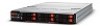
... Installing the Operating System 102 Installing with an External USB CD-ROM Drive 102 Installing via PXE Boot 102 Installing via Virtual Media 103 Acer Smart Console 104 Configuring BMC the IPMI Settings 104 AB460 F1 147 External and Internal Structure 147 KVM Connector 149 Front Panel LED Indicators 149 Blade Unit Components 150 Mainboard 152 CMOS Clear 153 Memory Support 154 Memory Installation 154 Populating Memory Slots 154 Hard Disk Drives 163 AB460 F1 System BIOS 165 Introduction 165 Starting the Setup Utility 165 BIOS Updates 166 Flashing BIOS...
... Installing the Operating System 102 Installing with an External USB CD-ROM Drive 102 Installing via PXE Boot 102 Installing via Virtual Media 103 Acer Smart Console 104 Configuring BMC the IPMI Settings 104 AB460 F1 147 External and Internal Structure 147 KVM Connector 149 Front Panel LED Indicators 149 Blade Unit Components 150 Mainboard 152 CMOS Clear 153 Memory Support 154 Memory Installation 154 Populating Memory Slots 154 Hard Disk Drives 163 AB460 F1 System BIOS 165 Introduction 165 Starting the Setup Utility 165 BIOS Updates 166 Flashing BIOS...
User Manual
Page 17
...AB2x280 F1 Hard Disk Drives 218 AB2x280 F1 System BIOS 219 Introduction 219 Starting the Setup Utility 219 BIOS Updates 220 Flashing BIOS 220 Running Setup 221 Main BIOS Setup 222 Advanced Settings 224 Boot 248 Exit Options 254 AB2x280 F1 Onboard SATA RAID Configuration 256 Enabling Adaptec onboard SATA RAID 257 4 Networking Switch Modules Acer 1/10Gb Ethernet Switch Module Installing/Removing a Switch Module Installing a Switch Module Removing a Switch Module Configuring the Switch Module Command Line Internal and External Structure Ports Web-based Management Utility...
...AB2x280 F1 Hard Disk Drives 218 AB2x280 F1 System BIOS 219 Introduction 219 Starting the Setup Utility 219 BIOS Updates 220 Flashing BIOS 220 Running Setup 221 Main BIOS Setup 222 Advanced Settings 224 Boot 248 Exit Options 254 AB2x280 F1 Onboard SATA RAID Configuration 256 Enabling Adaptec onboard SATA RAID 257 4 Networking Switch Modules Acer 1/10Gb Ethernet Switch Module Installing/Removing a Switch Module Installing a Switch Module Removing a Switch Module Configuring the Switch Module Command Line Internal and External Structure Ports Web-based Management Utility...
User Manual
Page 31
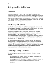
... sets of rail assemblies, two handles and the mounting screws you begin the installation procedure outlined in its entirety before you will hold the AB7000. The box the AB7000 was damaged in the next section. Please read this section in the sections that the processor(s) and memory have the system operational within a minimum amount of time. Choosing a Setup Location...
... sets of rail assemblies, two handles and the mounting screws you begin the installation procedure outlined in its entirety before you will hold the AB7000. The box the AB7000 was damaged in the next section. Please read this section in the sections that the processor(s) and memory have the system operational within a minimum amount of time. Choosing a Setup Location...
User Manual
Page 40
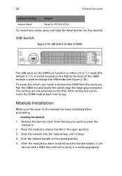
... CMM module back into the module bay until it is used to the closed position. 5. Slide the module into its bay. A switch located on the PCB at the back of CMM The USB ports on Rear of the CMM module is working properly. Push the release handle to change the USB mode (see Figure 2-10). The settings are silk screened on and a POST test will turn on...
... CMM module back into the module bay until it is used to the closed position. 5. Slide the module into its bay. A switch located on the PCB at the back of CMM The USB ports on Rear of the CMM module is working properly. Push the release handle to change the USB mode (see Figure 2-10). The settings are silk screened on and a POST test will turn on...

User Manual
Page 118
...). To Remove: Use your thumbs to gently push each DIMM vertically into place in . Repeat for each blade before installing. 5. Installing a DIMM into a Memory Slot To Install: Insert module vertically and press down on page 92). 2. Figure 3-58. Hard Disk Drive Installation Hard disk drives are installed in "carriers" which are hot-swappable and can be removed or replaced without powering down the blade module (see Figure 3-58). 98 3 Server Blades: Setup and Installation Installing DIMM Memory Modules 1. Power down the...
...). To Remove: Use your thumbs to gently push each DIMM vertically into place in . Repeat for each blade before installing. 5. Installing a DIMM into a Memory Slot To Install: Insert module vertically and press down on page 92). 2. Figure 3-58. Hard Disk Drive Installation Hard disk drives are installed in "carriers" which are hot-swappable and can be removed or replaced without powering down the blade module (see Figure 3-58). 98 3 Server Blades: Setup and Installation Installing DIMM Memory Modules 1. Power down the...

User Manual
Page 147
Remote Control - Main Menu 1 2 2 3 3 4 5 4 6 The Remote Access Main Menu includes the following items: 1 Remote Control: Click on this icon to configure Remote Control settings. 2 (Launch) Remote Console: Click this button to launch Remote Console. 3 (Launch) SOL: Click this button to enable Serial_Over_LAN support. 4 (Server) Power Control: Click this button to display server power state and to delete it from the list. When prompted, using the arrow keys, select a user from the network. the Main Menu This section allows the user to delete a user from the users list to...
Remote Control - Main Menu 1 2 2 3 3 4 5 4 6 The Remote Access Main Menu includes the following items: 1 Remote Control: Click on this icon to configure Remote Control settings. 2 (Launch) Remote Console: Click this button to launch Remote Console. 3 (Launch) SOL: Click this button to enable Serial_Over_LAN support. 4 (Server) Power Control: Click this button to display server power state and to delete it from the list. When prompted, using the arrow keys, select a user from the network. the Main Menu This section allows the user to delete a user from the users list to...

User Manual
Page 185
..., types of the BIOS Setup utility. As the memory is the memory test. in a flash chip. From the main menu, you can be changed by pressing the key at boot up. BIOS BIOS stands for AB460 F1 blade modules. How To Change the Configuration Data The CMOS information that is powered on it to enter the main menu of disk drives, video displays, etc. When the blade unit is turned off, a backup battery provides power to the BIOS flash chip, enabling it is configured...
..., types of the BIOS Setup utility. As the memory is the memory test. in a flash chip. From the main menu, you can be changed by pressing the key at boot up. BIOS BIOS stands for AB460 F1 blade modules. How To Change the Configuration Data The CMOS information that is powered on it to enter the main menu of disk drives, video displays, etc. When the blade unit is turned off, a backup battery provides power to the BIOS flash chip, enabling it is configured...

User Manual
Page 186
.... 4. Connect your bootable USB pen drive to one of the two USB slots on the CMM (located on the back side of the methods described below to "Flash" your BIOS. Type flash filename.rom (replace filename.rom by the actual ROM file name). Boot to the USB pen drive and go to the directory where you may be flashing the BIOS to. 3. 166 3 Server Blades: Setup and Installation BIOS Updates It may use to upgrade (flash) your BIOS...
.... 4. Connect your bootable USB pen drive to one of the two USB slots on the CMM (located on the back side of the methods described below to "Flash" your BIOS. Type flash filename.rom (replace filename.rom by the actual ROM file name). Boot to the USB pen drive and go to the directory where you may be flashing the BIOS to. 3. 166 3 Server Blades: Setup and Installation BIOS Updates It may use to upgrade (flash) your BIOS...

User Manual
Page 229
... used to backplane) BIOS Chip Onboard Battery Intel 5500 Chip ICH10R Chip Front IO Module Matrox G200eW Graphics chip JPT1 (CMOS clear) Jumpers The jumpers present on . 209 Item 1 2 3 4 5 6 7 8 9 10 11 Description CPU Sockets DIMM Slots Space for 2.5" SATA Hard Drive Gbx Connector (for further details). Remove the blade cover to access the mainboard (see Section : Removing/Replacing the Blade Cover on page 93 for power and logic to clear CMOS and will also clear any passwords...
... used to backplane) BIOS Chip Onboard Battery Intel 5500 Chip ICH10R Chip Front IO Module Matrox G200eW Graphics chip JPT1 (CMOS clear) Jumpers The jumpers present on . 209 Item 1 2 3 4 5 6 7 8 9 10 11 Description CPU Sockets DIMM Slots Space for 2.5" SATA Hard Drive Gbx Connector (for further details). Remove the blade cover to access the mainboard (see Section : Removing/Replacing the Blade Cover on page 93 for power and logic to clear CMOS and will also clear any passwords...

User Manual
Page 239
... turned off, a backup battery provides power to the BIOS flash chip, enabling it is being tested, press the key to retain system parameters. How To Change the Configuration Data The CMOS information that is the memory test. Warning! To prevent possible boot failure, do not shut down or reset the system while updating the BIOS. in the BIOS ROM by entering the BIOS Setup utility. This Setup utility can be easily upgraded using a floppy disk-based program. From the main menu...
... turned off, a backup battery provides power to the BIOS flash chip, enabling it is being tested, press the key to retain system parameters. How To Change the Configuration Data The CMOS information that is the memory test. Warning! To prevent possible boot failure, do not shut down or reset the system while updating the BIOS. in the BIOS ROM by entering the BIOS Setup utility. This Setup utility can be easily upgraded using a floppy disk-based program. From the main menu...

User Manual
Page 294
... open source communities and is essentially provided for constructing a switched/routed network. For example, if the management IP address of a failure to boot from OpenSSL, OpenSSH and other switching ports, then you can be changed in the SYSTEM SETTINGS page in order to hold two firmware images. The switch has internal flash memory in the address space of this switch. This IP address is configured using web browsers such as wire speed...
... open source communities and is essentially provided for constructing a switched/routed network. For example, if the management IP address of a failure to boot from OpenSSL, OpenSSH and other switching ports, then you can be changed in the SYSTEM SETTINGS page in order to hold two firmware images. The switch has internal flash memory in the address space of this switch. This IP address is configured using web browsers such as wire speed...

User Manual
Page 572
... physical connection Port Activity LED (Yellow) Steady On Logic link established, no activity Blinking Data transferring to upgrade the firmware and monitor temperature, voltages, port utilization and other switch parameters. 552 4 Networking Switch Modules LED State Indication Description Module Power LED (Green) Steady On Off Switch has power and is operational There is a problem with the power being supplied to download on Mellanox's web site: • http://www.mellanox.com/content/ pages.php?pg=software_overview_ib&menu_section=34 Both software...
... physical connection Port Activity LED (Yellow) Steady On Logic link established, no activity Blinking Data transferring to upgrade the firmware and monitor temperature, voltages, port utilization and other switch parameters. 552 4 Networking Switch Modules LED State Indication Description Module Power LED (Green) Steady On Off Switch has power and is operational There is a problem with the power being supplied to download on Mellanox's web site: • http://www.mellanox.com/content/ pages.php?pg=software_overview_ib&menu_section=34 Both software...
User Manual
Page 603
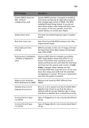
... but fails the BIOS POST diskette tests. Check to run SETUP Type of floppy drive B: not correctly identified in Setup. 583 BIOS Message Description System CMOS checksum bad - On systems with the proper diskette type in CMOS. Real time clock error Real-Time Clock fails BIOS hardware test. May require board repair. System timer error The timer test failed. The BIOS installed Default Setup Values. Incorrect Drive A type run SETUP Type of wait states, improper Setup settings can also terminate POST and cause this error on the next boot. Incorrect Drive B type run...
... but fails the BIOS POST diskette tests. Check to run SETUP Type of floppy drive B: not correctly identified in Setup. 583 BIOS Message Description System CMOS checksum bad - On systems with the proper diskette type in CMOS. Real time clock error Real-Time Clock fails BIOS hardware test. May require board repair. System timer error The timer test failed. The BIOS installed Default Setup Values. Incorrect Drive A type run SETUP Type of wait states, improper Setup settings can also terminate POST and cause this error on the next boot. Incorrect Drive B type run...

User Manual
Page 604
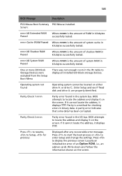
... Data Problem with NVRAM (CMOS) data. I/O device IRQ conflict I/O device IRQ conflict error. Cache disabled RAM cache failed and BIOS disabled the cache. A disabled cache slows system performance considerably. CPU ID: CPU socket number for : device Run ISA or EISA Configuration Utility to extended DMA (Direct Memory Access) registers. Fail-Safe Timer NMI Failed ServerBIOS2 test error: Fail-Safe Timer takes too long. Entering SETUP... On older boards, check the cache jumpers. CD ROM Drive CD ROM Drive identified. 584 Appendix A: Troubleshooting BIOS Message...
... Data Problem with NVRAM (CMOS) data. I/O device IRQ conflict I/O device IRQ conflict error. Cache disabled RAM cache failed and BIOS disabled the cache. A disabled cache slows system performance considerably. CPU ID: CPU socket number for : device Run ISA or EISA Configuration Utility to extended DMA (Direct Memory Access) registers. Fail-Safe Timer NMI Failed ServerBIOS2 test error: Fail-Safe Timer takes too long. Entering SETUP... On older boards, check the cache jumpers. CD ROM Drive CD ROM Drive identified. 584 Appendix A: Troubleshooting BIOS Message...
User Manual
Page 605
... add-on the screen. If it cannot locate the address, it displays ????. Write down and follow the information shown on the screen. Enter Setup and see if fixed disk and drive A: are properly identified. A parity error indicates that some data has been corrupted. Press to start the boot process or to display all installed I2O block-storage devices. Press to locate the address and display it on card). 585 BIOS Message...
... add-on the screen. If it cannot locate the address, it displays ????. Write down and follow the information shown on the screen. Enter Setup and see if fixed disk and drive A: are properly identified. A parity error indicates that some data has been corrupted. Press to start the boot process or to display all installed I2O block-storage devices. Press to locate the address and display it on card). 585 BIOS Message...

User Manual
Page 607
... POST (Power-On Self-Test) codes for the AMI BIOS. video configuration error • One repetitive long beep - POST codes are divided into two categories: recoverable and terminal. no memory detected Terminal POST Errors If a terminal type of error occurs, BIOS will write the error to port 80h, attempt to initialize video and write the error in the top left corner of the screen. Post Code Description 02h Verify Real Mode 03h Disable Non-Maskable Interrupt (NMI...
... POST (Power-On Self-Test) codes for the AMI BIOS. video configuration error • One repetitive long beep - POST codes are divided into two categories: recoverable and terminal. no memory detected Terminal POST Errors If a terminal type of error occurs, BIOS will write the error to port 80h, attempt to initialize video and write the error in the top left corner of the screen. Post Code Description 02h Verify Real Mode 03h Disable Non-Maskable Interrupt (NMI...
User Manual
Page 610
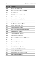
... Multi Processor APIC 68h Enable external and CPU caches 69h Setup System Management Mode (SMM) area 6Ah Display external L2 cache size 6Bh Load custom defaults (optional) 6Ch Display shadow-area message 6Eh Display possible high address for UMB recovery 70h Display error messages 72h Check for configuration errors 76h Check for keyboard errors 7Ch Set up hardware interrupt vectors 7Dh Initialize Intelligent System Monitoring 7Eh Initialize coprocessor if present 80h Disable onboard Super I/O ports and...
... Multi Processor APIC 68h Enable external and CPU caches 69h Setup System Management Mode (SMM) area 6Ah Display external L2 cache size 6Bh Load custom defaults (optional) 6Ch Display shadow-area message 6Eh Display possible high address for UMB recovery 70h Display error messages 72h Check for configuration errors 76h Check for keyboard errors 7Ch Set up hardware interrupt vectors 7Dh Initialize Intelligent System Monitoring 7Eh Initialize coprocessor if present 80h Disable onboard Super I/O ports and...
User Manual
Page 614
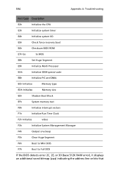
... I/O E5h Check force recovery boot E6h Checksum BIOS ROM E7h Go to BIOS E8h Set Huge Segment E9h Initialize Multi Processor EAh Initialize OEM special code EBh Initialize PIC and DMA ECh Initialize Memory type EDh Initialize Memory size EEh Shadow Boot Block EFh System memory test F0h Initialize interrupt vectors F1h Initialize Run Time Clock F2h Initialize video F3h Initialize System Management Manager F4h Output one beep F5h Clear Huge...
... I/O E5h Check force recovery boot E6h Checksum BIOS ROM E7h Go to BIOS E8h Set Huge Segment E9h Initialize Multi Processor EAh Initialize OEM special code EBh Initialize PIC and DMA ECh Initialize Memory type EDh Initialize Memory size EEh Shadow Boot Block EFh System memory test F0h Initialize interrupt vectors F1h Initialize Run Time Clock F2h Initialize video F3h Initialize System Management Manager F4h Output one beep F5h Clear Huge...

User Manual
Page 617
... A AB2x280 F1 BIOS 219 Components 206 Hard Disk Drives 218 Mainboard 208 Onboard SATA RAID Con figuration 256 AB460 F1 147 BIOS 165 Components 150 Hard Disk Drives 163 Mainboard 152 Memory Installation 154 Onboard SA S RA ID Con figuration 201 Acer Smart Blade Console 28 Blade System 32 Device Settings 57 Home Page 29 KVM 52 Maintenance 67 Network Connection/Login 28 Remote Console 71 System Health 45 User Management 47 Virtual Media 40 Acer Smart Blade Manager 554 Acer switch 561 Blade...
... A AB2x280 F1 BIOS 219 Components 206 Hard Disk Drives 218 Mainboard 208 Onboard SATA RAID Con figuration 256 AB460 F1 147 BIOS 165 Components 150 Hard Disk Drives 163 Mainboard 152 Memory Installation 154 Onboard SA S RA ID Con figuration 201 Acer Smart Blade Console 28 Blade System 32 Device Settings 57 Home Page 29 KVM 52 Maintenance 67 Network Connection/Login 28 Remote Console 71 System Health 45 User Management 47 Virtual Media 40 Acer Smart Blade Manager 554 Acer switch 561 Blade...

User Manual
Page 618
...A B2x280 F1 212 Module Acer 1/10 Ethernet Switch 262 Configuring a Switch 265 Double-Wide 87 Installing a Switch 263 Power Supply 80 Rear 10 Removing a Switch 264 Switch Web-based Management Utility 274 Monitoring Functions 26 O Operating System Installing 102 P Power Components 84 Power Co nsumption Management 26 Power Supply Acer Smart Blade Console 34 Acer Smart Blade Manager 559, 569 Failure 81 Fans 83 Installing 81 Removing 82 Power Supply Modules 80 Processor Installation 95 R Rack Mounting Considerations 13 Mounting Hardware 14 Precautions 12 Rear Panel 8 S safety CD or DVD xiii Server...
...A B2x280 F1 212 Module Acer 1/10 Ethernet Switch 262 Configuring a Switch 265 Double-Wide 87 Installing a Switch 263 Power Supply 80 Rear 10 Removing a Switch 264 Switch Web-based Management Utility 274 Monitoring Functions 26 O Operating System Installing 102 P Power Components 84 Power Co nsumption Management 26 Power Supply Acer Smart Blade Console 34 Acer Smart Blade Manager 559, 569 Failure 81 Fans 83 Installing 81 Removing 82 Power Supply Modules 80 Processor Installation 95 R Rack Mounting Considerations 13 Mounting Hardware 14 Precautions 12 Rear Panel 8 S safety CD or DVD xiii Server...


