
Intel Smart Response Installation Guide
Page 1
... "Enable Acceleration" button on the GUI panel. 5. You can find the UI setup instruction and the step by double-clicking RST Storage icon in system at this point! 3. Boot system to accelerate AND the SSD in Icon tray, lower right-hand corner of the screen. 4. Once open RST GUI from either Start Menu or by step instructions below. Intel Smart Response Technology Installation Guide This motherboard supports...
... "Enable Acceleration" button on the GUI panel. 5. You can find the UI setup instruction and the step by double-clicking RST Storage icon in system at this point! 3. Boot system to accelerate AND the SSD in Icon tray, lower right-hand corner of the screen. 4. Once open RST GUI from either Start Menu or by step instructions below. Intel Smart Response Technology Installation Guide This motherboard supports...

Intel Rapid Storage Guide
Page 12
... the RAID level and press Enter. 4. Click the Storage Configuration menu. 4. Select 1: Create RAID Volume and press Enter. 3. Use the up or down arrow keys to select the drive. Switch the SATA Operation Mode option to enter the option ROM user interface. 2. Click F2 or Delete to save the BIOS settings and exit the BIOS Setup program. Click F10 to enter the BIOS Setup program after the Power-On-Self-Test (POST) memory test begins. 2. Create a RAID Volume Use the...
... the RAID level and press Enter. 4. Click the Storage Configuration menu. 4. Select 1: Create RAID Volume and press Enter. 3. Use the up or down arrow keys to select the drive. Switch the SATA Operation Mode option to enter the option ROM user interface. 2. Click F2 or Delete to save the BIOS settings and exit the BIOS Setup program. Click F10 to enter the BIOS Setup program after the Power-On-Self-Test (POST) memory test begins. 2. Create a RAID Volume Use the...
Intel Rapid Storage Guide
Page 13
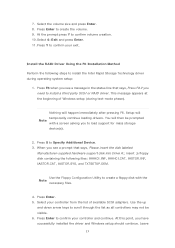
...-supplied hardware support disk into Drive A:, insert ;a floppy disk containing the following steps to install the Intel Rapid Storage Technology driver during text-mode phase). Use the Floppy Configuration Utility to install a third party SCSI or RAID driver. Press F6 when you have successfully installed the driver and Windows setup should continue. Select your exit. Press Y to load support for mass storage device(s). 2. Press Enter. 5. Leave 13 You will then be visible. 6. 7. Use the up and down arrow keys...
...-supplied hardware support disk into Drive A:, insert ;a floppy disk containing the following steps to install the Intel Rapid Storage Technology driver during text-mode phase). Use the Floppy Configuration Utility to install a third party SCSI or RAID driver. Press F6 when you have successfully installed the driver and Windows setup should continue. Select your exit. Press Y to load support for mass storage device(s). 2. Press Enter. 5. Leave 13 You will then be visible. 6. 7. Use the up and down arrow keys...
User Manual
Page 4
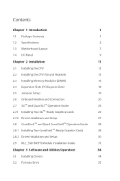
...Specifications 2 1.3 Motherboard Layout 7 1.4 I/O Panel 9 Chapter 2 Installation 11 2.1 Installing the CPU 12 2.2 Installing the CPU Fan and Heatsink 15 2.3 Installing Memory Modules (DIMM) 16 2.4 Expansion Slots (PCI Express Slots) 18 2.5 Jumpers Setup 19 2.6 Onboard Headers and Connectors 20 2.7 SLITM and Quad SLITM Operation Guide 25 2.7.1 Installing Two SLITM-Ready Graphics Cards 25 2.7.2 Driver Installation and Setup 27 2.8 CrossFireXTM and Quad CrossFireXTM Operation Guide 28 2.8.1 Installing Two CrossFireXTM-Ready Graphics Cards 28 2.8.2 Driver Installation...
...Specifications 2 1.3 Motherboard Layout 7 1.4 I/O Panel 9 Chapter 2 Installation 11 2.1 Installing the CPU 12 2.2 Installing the CPU Fan and Heatsink 15 2.3 Installing Memory Modules (DIMM) 16 2.4 Expansion Slots (PCI Express Slots) 18 2.5 Jumpers Setup 19 2.6 Onboard Headers and Connectors 20 2.7 SLITM and Quad SLITM Operation Guide 25 2.7.1 Installing Two SLITM-Ready Graphics Cards 25 2.7.2 Driver Installation and Setup 27 2.8 CrossFireXTM and Quad CrossFireXTM Operation Guide 28 2.8.1 Installing Two CrossFireXTM-Ready Graphics Cards 28 2.8.2 Driver Installation...
User Manual
Page 8
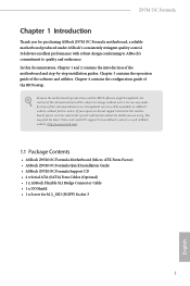
...) • ASRock Z97M OC Formula Quick Installation Guide • ASRock Z97M OC Formula Support CD • 2 x Serial ATA (SATA) Data Cables (Optional) • 1 x ASRock Flexible SLI Bridge Connector Cable • 1 x I/O Shield • 1 x Screw for specific information about the model you are using. If you for purchasing ASRock Z97M OC Formula motherboard, a reliable motherboard produced under ASRock's consistently stringent quality control. Chapter 3 contains the operation guide of the BIOS setup. In case any modifications of this documentation occur, the updated version will be...
...) • ASRock Z97M OC Formula Quick Installation Guide • ASRock Z97M OC Formula Support CD • 2 x Serial ATA (SATA) Data Cables (Optional) • 1 x ASRock Flexible SLI Bridge Connector Cable • 1 x I/O Shield • 1 x Screw for specific information about the model you are using. If you for purchasing ASRock Z97M OC Formula motherboard, a reliable motherboard produced under ASRock's consistently stringent quality control. Chapter 3 contains the operation guide of the BIOS setup. In case any modifications of this documentation occur, the updated version will be...
User Manual
Page 12
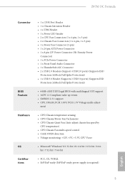
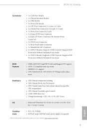
...x PCIe Power Connector • 1 x Front Panel Audio Connector • 1 x Thunderbolt AIC Connector • 2 x USB 2.0 Headers (Support 4 USB 2.0 ports) (Supports ESD Protection (ASRock Full Spike Protection)) • 1 x USB 3.0 Header (Supports 2 USB 3.0 ports) (Supports ESD Protection (ASRock Full Spike Protection)) BIOS Feature • 64Mb AMI UEFI Legal BIOS with multilingual GUI support • ACPI 1.1 Compliant wake up events • SMBIOS 2.3.1 support • CPU, DRAM, PCH 1.05V, PCH 1.5V Voltage multi-adjust- ment Hardware • CPU/Chassis temperature sensing • CPU...
...x PCIe Power Connector • 1 x Front Panel Audio Connector • 1 x Thunderbolt AIC Connector • 2 x USB 2.0 Headers (Support 4 USB 2.0 ports) (Supports ESD Protection (ASRock Full Spike Protection)) • 1 x USB 3.0 Header (Supports 2 USB 3.0 ports) (Supports ESD Protection (ASRock Full Spike Protection)) BIOS Feature • 64Mb AMI UEFI Legal BIOS with multilingual GUI support • ACPI 1.1 Compliant wake up events • SMBIOS 2.3.1 support • CPU, DRAM, PCH 1.05V, PCH 1.5V Voltage multi-adjust- ment Hardware • CPU/Chassis temperature sensing • CPU...
User Manual
Page 28
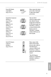
... of SATAE_1, SATA3_4, and SATA3_5. PLED+ PLED+ SATA3_4 SATA3_3 Please connect the chassis power LED to this connector. These six SATA3 connectors support SATA data cables for internal storage devices with up to indicate the system's power status. The SATA3_4, SATA3_5 are shared with the eSATA1 port on the I/O panel.. Z97M OC Formula Power LED Header (3-pin PLED1) (see p.7, No. 17) Serial ATA3 Connectors (SATA3_0) (see p.7, No. 8) (SATA3_1) (see p.7, No. 10) (SATA3_2) (see p.7, No...
... of SATAE_1, SATA3_4, and SATA3_5. PLED+ PLED+ SATA3_4 SATA3_3 Please connect the chassis power LED to this connector. These six SATA3 connectors support SATA data cables for internal storage devices with up to indicate the system's power status. The SATA3_4, SATA3_5 are shared with the eSATA1 port on the I/O panel.. Z97M OC Formula Power LED Header (3-pin PLED1) (see p.7, No. 17) Serial ATA3 Connectors (SATA3_0) (see p.7, No. 8) (SATA3_1) (see p.7, No. 10) (SATA3_2) (see p.7, No...
User Manual
Page 30
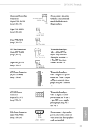
... motherboard provides a 4-Pin CPU fan (Quiet Fan) connector. To use a 20-pin ATX power supply, please plug it to Pin 1-3. Z97M OC Formula Chassis and Power Fan Connectors (4-pin CHA_FAN1) (see p.7, No. 19) (3-pin CHA_FAN2) (see p.7, No. 26) (3-pin PWR_FAN1) (see p.7, No. 27) CPU Fan Connectors (4-pin CPU_FAN1) (see p.7, No. 3) (3-pin CPU_FAN2) (see p.7, No. 2) ATX Power Connector (24-pin ATXPWR1) (see p.7, No. 24) GND +12V DETECT Please connect a 4 pin molex power cable to this connector when more than three graphics cards are installed. 23 English PCIe Power Connector (4-pin...
... motherboard provides a 4-Pin CPU fan (Quiet Fan) connector. To use a 20-pin ATX power supply, please plug it to Pin 1-3. Z97M OC Formula Chassis and Power Fan Connectors (4-pin CHA_FAN1) (see p.7, No. 19) (3-pin CHA_FAN2) (see p.7, No. 26) (3-pin PWR_FAN1) (see p.7, No. 27) CPU Fan Connectors (4-pin CPU_FAN1) (see p.7, No. 3) (3-pin CPU_FAN2) (see p.7, No. 2) ATX Power Connector (24-pin ATXPWR1) (see p.7, No. 24) GND +12V DETECT Please connect a 4 pin molex power cable to this connector when more than three graphics cards are installed. 23 English PCIe Power Connector (4-pin...
User Manual
Page 35
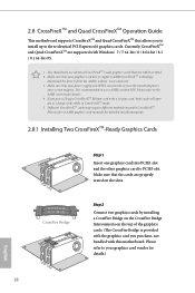
...-ready graphics cards that allows you to install up to the AMD's website for details.) English 28 Please refer to three identical PCI Express x16 graphics cards. You should only use a AMD certified PSU. Please refer to AMD graphics card manuals for detailed installation guide. 2.8.1 Installing Two CrossFireXTM-Ready Graphics Cards CrossFire Bridge Step 1 Insert one graphics card into PCIE1 slot and the other graphics card to enable CrossFireXTM. 2.8 CrossFireXTM and Quad CrossFireXTM Operation Guide This motherboard supports...
...-ready graphics cards that allows you to install up to the AMD's website for details.) English 28 Please refer to three identical PCI Express x16 graphics cards. You should only use a AMD certified PSU. Please refer to AMD graphics card manuals for detailed installation guide. 2.8.1 Installing Two CrossFireXTM-Ready Graphics Cards CrossFire Bridge Step 1 Insert one graphics card into PCIE1 slot and the other graphics card to enable CrossFireXTM. 2.8 CrossFireXTM and Quad CrossFireXTM Operation Guide This motherboard supports...

User Manual
Page 37
... previously installed Catalyst drivers prior to installation. The Catalyst Uninstaller is an optional download. AMD Catalyst Control Center Step 4 Double-click the AMD Catalyst Control Center icon in your graphics card and click Apply. Then select Enable AMD CrossFireX and click Apply. 2.8.2 Driver Installation and Setup Step 1 Power on your computer. Please check AMD's website for details. Step 3 Install the required drivers and CATALYST Control Center then restart your computer and boot...
... previously installed Catalyst drivers prior to installation. The Catalyst Uninstaller is an optional download. AMD Catalyst Control Center Step 4 Double-click the AMD Catalyst Control Center icon in your graphics card and click Apply. Then select Enable AMD CrossFireX and click Apply. 2.8.2 Driver Installation and Setup Step 1 Power on your computer. Please check AMD's website for details. Step 3 Install the required drivers and CATALYST Control Center then restart your computer and boot...

User Manual
Page 41
... the Main Menu does not appear automatically, locate and double click on the file "ASRSETUP.EXE" in your computer. Drivers Menu The drivers compatible to install those required drivers. Utilities Menu The Utilities Menu shows the application software that enhance the motherboard's features. Click on the support CD driver page. Running The Support CD To begin using the support CD, insert the CD into your system will be auto-detected and listed on a specific...
... the Main Menu does not appear automatically, locate and double click on the file "ASRSETUP.EXE" in your computer. Drivers Menu The drivers compatible to install those required drivers. Utilities Menu The Utilities Menu shows the application software that enhance the motherboard's features. Click on the support CD driver page. Running The Support CD To begin using the support CD, insert the CD into your system will be auto-detected and listed on a specific...
User Manual
Page 56
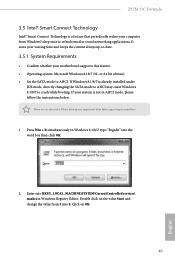
... If Windows 8.1/8/7 is already installed under IDE mode, directly changing the SATA mode to AHCI may cause Windows 8.1/8/7 to AHCI. Click on the value Start and change the value from Windows® sleep state to avoid loss. 1. Z97M OC Formula 3.5 Intel® Smart Connect Technology Intel® Smart Connect Technology is a feature that periodically wakes your motherboard supports this feature. • Operating system: Microsoft Windows 8.18/7 (32- If your system is not in AHCI mode, please follow the instructions below...
... If Windows 8.1/8/7 is already installed under IDE mode, directly changing the SATA mode to AHCI may cause Windows 8.1/8/7 to AHCI. Click on the value Start and change the value from Windows® sleep state to avoid loss. 1. Z97M OC Formula 3.5 Intel® Smart Connect Technology Intel® Smart Connect Technology is a feature that periodically wakes your motherboard supports this feature. • Operating system: Microsoft Windows 8.18/7 (32- If your system is not in AHCI mode, please follow the instructions below...

User Manual
Page 86
... option appears only when you adopt K-Series CPU. Load Optimized GPU OC Setting You can set up overclocking features. 4.3 OC Tweaker Screen In the OC Tweaker screen, you can use this option to load optimized GPU overclocking setting. Please note that overclocking may not exactly match what you see on your GPU and motherboard. It should be done at your CPU supports this function. Z97M OC Formula Because the UEFI software is constantly being updated, the following UEFI setup screens...
... option appears only when you adopt K-Series CPU. Load Optimized GPU OC Setting You can set up overclocking features. 4.3 OC Tweaker Screen In the OC Tweaker screen, you can use this option to load optimized GPU overclocking setting. Please note that overclocking may not exactly match what you see on your GPU and motherboard. It should be done at your CPU supports this function. Z97M OC Formula Because the UEFI software is constantly being updated, the following UEFI setup screens...
User Manual
Page 99
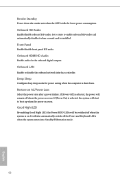
... power recovers. Front Panel Enable/disable front panel HD audio. If [Power On] is selected, the system will remain off the Power and Keyboard LEDs when the system enters into Standby/Hibernation mode. 92 English Onboard LAN Enable or disable the onboard network interface controller. Onboard HD Audio Enable/disable onboard HD audio. If [Power Off] is selected, the power will start to enable onboard HD audio and automatically disable it when a sound card is installed. Good Night LED By enabling Good Night LED, the Power/HDD LEDs will also automatically switch...
... power recovers. Front Panel Enable/disable front panel HD audio. If [Power On] is selected, the system will remain off the Power and Keyboard LEDs when the system enters into Standby/Hibernation mode. 92 English Onboard LAN Enable or disable the onboard network interface controller. Onboard HD Audio Enable/disable onboard HD audio. If [Power Off] is selected, the power will start to enable onboard HD audio and automatically disable it when a sound card is installed. Good Night LED By enabling Good Night LED, the Power/HDD LEDs will also automatically switch...
User Manual
Page 105
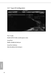
4.4.7 Super IO Configuration PS2 Y-Cable Enable the PS2 Y-Cable or set this option to Auto. Serial Port Address Select the address of the Serial port. 98 English Serial Port Enable or disable the Serial port.
4.4.7 Super IO Configuration PS2 Y-Cable Enable the PS2 Y-Cable or set this option to Auto. Serial Port Address Select the address of the Serial port. 98 English Serial Port Enable or disable the Serial port.
User Manual
Page 108
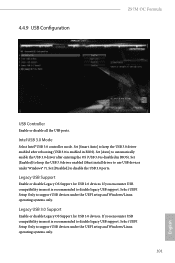
...Intel USB 3.0 Mode Select Intel® USB 3.0 controller mode. Set [Smart Auto] to automatically enable the USB 3.0 driver after rebooting (USB 3.0 is recommended to disable the USB 3.0 ports. If you encounter USB compatibility issues it is disabled in BIOS). Legacy USB Support Enable or disable Legacy OS Support for USB 3.0 devices. Select UEFI Setup Only to disable legacy USB support. 4.4.9 USB Configuration Z97M OC Formula USB Controller Enable or disable all the USB ports. Set [Auto] to keep the USB 3.0 driver enabled (Must install driver to support USB devices under...
...Intel USB 3.0 Mode Select Intel® USB 3.0 controller mode. Set [Smart Auto] to automatically enable the USB 3.0 driver after rebooting (USB 3.0 is recommended to disable the USB 3.0 ports. If you encounter USB compatibility issues it is disabled in BIOS). Legacy USB Support Enable or disable Legacy OS Support for USB 3.0 devices. Select UEFI Setup Only to disable legacy USB support. 4.4.9 USB Configuration Z97M OC Formula USB Controller Enable or disable all the USB ports. Set [Auto] to keep the USB 3.0 driver enabled (Must install driver to support USB devices under...

User Manual
Page 112
... drivers automatically. Please setup network configuration before using Internet Flash. *For BIOS backup and recovery purpose, it is a handy tool in the UEFI that installs the LAN driver to your UEFI. DHCP (Auto IP), Auto ASRock Internet Flash downloads and updates the latest UEFI firmware version from our servers for Internet Flash. UEFI Download Server Select a server to download the UEFI firmware. 105 English Internet Setting Enable or disable sound effects in the setup utility. Z97M OC Formula CD, Easy Driver Installer is recommended to plug in your USB pen drive before using...
... drivers automatically. Please setup network configuration before using Internet Flash. *For BIOS backup and recovery purpose, it is a handy tool in the UEFI that installs the LAN driver to your UEFI. DHCP (Auto IP), Auto ASRock Internet Flash downloads and updates the latest UEFI firmware version from our servers for Internet Flash. UEFI Download Server Select a server to download the UEFI firmware. 105 English Internet Setting Enable or disable sound effects in the setup utility. Z97M OC Formula CD, Easy Driver Installer is recommended to plug in your USB pen drive before using...
RAID Installation Guide
Page 7
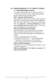
... BIOS setup. Plug in the BIOS before you want to install Windows® 8.1 / 8.1 64-bit /8 / 8 64-bit / 7 / 7 64-bit OS on your system. 7 STEP 1: Setting the BIOS RAID Items After installing the hard disk drives, please set the option SATA Mode Selection to [RAID]. STEP 2: Use ASRock Easy RAID Installer Easy RAID Installer can copy the RAID driver from a support CD to confirm the selection C. Enter UEFI SETUP UTILITY Tool and highlight "Easy RAID Installer". STEP 4: Install Windows® 8.1 / 8.1 64-bit / 8 / 8 64-bit / 7 / 7 64-bit OS on your SATA / SATA2 / SATA3 HDDs...
... BIOS setup. Plug in the BIOS before you want to install Windows® 8.1 / 8.1 64-bit /8 / 8 64-bit / 7 / 7 64-bit OS on your system. 7 STEP 1: Setting the BIOS RAID Items After installing the hard disk drives, please set the option SATA Mode Selection to [RAID]. STEP 2: Use ASRock Easy RAID Installer Easy RAID Installer can copy the RAID driver from a support CD to confirm the selection C. Enter UEFI SETUP UTILITY Tool and highlight "Easy RAID Installer". STEP 4: Install Windows® 8.1 / 8.1 64-bit / 8 / 8 64-bit / 7 / 7 64-bit OS on your SATA / SATA2 / SATA3 HDDs...
Quick Installation Guide
Page 11
...Power Connector) • 1 x PCIe Power Connector • 1 x Front Panel Audio Connector • 1 x Thunderbolt AIC Connector • 2 x USB 2.0 Headers (Support 4 USB 2.0 ports) (Supports ESD Protection (ASRock Full Spike Protection)) • 1 x USB 3.0 Header (Supports 2 USB 3.0 ports) (Supports ESD Protection (ASRock Full Spike Protection)) BIOS Feature • 64Mb AMI UEFI Legal BIOS with multilingual GUI support • ACPI 1.1 Compliant wake up events • SMBIOS 2.3.1 support • CPU, DRAM, PCH 1.05V, PCH 1.5V Voltage multi-adjust- ment Hardware • CPU/Chassis...
...Power Connector) • 1 x PCIe Power Connector • 1 x Front Panel Audio Connector • 1 x Thunderbolt AIC Connector • 2 x USB 2.0 Headers (Support 4 USB 2.0 ports) (Supports ESD Protection (ASRock Full Spike Protection)) • 1 x USB 3.0 Header (Supports 2 USB 3.0 ports) (Supports ESD Protection (ASRock Full Spike Protection)) BIOS Feature • 64Mb AMI UEFI Legal BIOS with multilingual GUI support • ACPI 1.1 Compliant wake up events • SMBIOS 2.3.1 support • CPU, DRAM, PCH 1.05V, PCH 1.5V Voltage multi-adjust- ment Hardware • CPU/Chassis...

Quick Installation Guide
Page 25
...and Pin 13. Z97M OC Formula Chassis and Power Fan Connectors (4-pin CHA_FAN1) (see p.11, No. 19) (3-pin CHA_FAN2) (see p.1, No. 26) (3-pin PWR_FAN1) (see p.1, No. 27) CPU Fan Connectors (4-pin CPU_FAN1) (see p.1, No. 3) (3-pin CPU_FAN2) (see p.1, No. 2) ATX Power Connector (24-pin ATXPWR1) (see p.1, No. 6) FAN_SPEED_CONTROL CHA_FAN_SPEED +12V GND Please connect fan cables to the fan connectors and match the black wire to this connector when more than three graphics cards are installed. 23 English PCIe Power Connector (4-pin PCIE_PWR1) (see p.1, No. 1) 8 5 This motherboard pro...
...and Pin 13. Z97M OC Formula Chassis and Power Fan Connectors (4-pin CHA_FAN1) (see p.11, No. 19) (3-pin CHA_FAN2) (see p.1, No. 26) (3-pin PWR_FAN1) (see p.1, No. 27) CPU Fan Connectors (4-pin CPU_FAN1) (see p.1, No. 3) (3-pin CPU_FAN2) (see p.1, No. 2) ATX Power Connector (24-pin ATXPWR1) (see p.1, No. 6) FAN_SPEED_CONTROL CHA_FAN_SPEED +12V GND Please connect fan cables to the fan connectors and match the black wire to this connector when more than three graphics cards are installed. 23 English PCIe Power Connector (4-pin PCIE_PWR1) (see p.1, No. 1) 8 5 This motherboard pro...


