
Intel Smart Response Installation Guide
Page 1
... system to use Enhanced or Maximized Mode. 6. Intel Smart Response Technology Installation Guide This motherboard supports Intel Smart Response Technology. For the new version RST driver, please check our website for the latest information: http://www.asrock.com * Before you use the full SSD as Cache device or only 20GB, and if...
... system to use Enhanced or Maximized Mode. 6. Intel Smart Response Technology Installation Guide This motherboard supports Intel Smart Response Technology. For the new version RST driver, please check our website for the latest information: http://www.asrock.com * Before you use the full SSD as Cache device or only 20GB, and if...

Intel Rapid Storage Guide
Page 12
... or Delete to select the physical disks. 6. Select 1: Create RAID Volume and press Enter. 3. Enable RAID in System BIOS Use the instructions included with your motherboard to select the RAID level and press Enter. 4.
... or Delete to select the physical disks. 6. Select 1: Create RAID Volume and press Enter. 3. Enable RAID in System BIOS Use the instructions included with your motherboard to select the RAID level and press Enter. 4.
RAID Installation Guide
Page 2
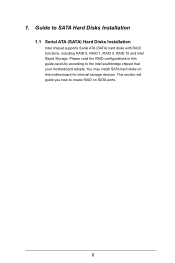
Guide to the Intel southbridge chipset that your motherboard adopts. This section will guide you how to create RAID on this guide carefully according to SATA Hard Disks Installation 1.1 Serial ATA (SATA) Hard Disks Installation Intel chipset supports Serial ATA (SATA) hard disks with RAID functions, including RAID 0, RAID 1, RAID 5, RAID 10 and Intel Rapid Storage. Please read the RAID configurations in this motherboard for internal storage devices. 1. You may install SATA hard disks on SATA ports. 2
Guide to the Intel southbridge chipset that your motherboard adopts. This section will guide you how to create RAID on this guide carefully according to SATA Hard Disks Installation 1.1 Serial ATA (SATA) Hard Disks Installation Intel chipset supports Serial ATA (SATA) hard disks with RAID functions, including RAID 0, RAID 1, RAID 5, RAID 10 and Intel Rapid Storage. Please read the RAID configurations in this motherboard for internal storage devices. 1. You may install SATA hard disks on SATA ports. 2
RAID Installation Guide
Page 3
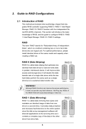
... a complete copy of a single disk alone while the two hard disks perform the same work as it does not provide any HDDs of RAID This motherboard adopts Intel southbridge chipset that optimizes two identical hard disk drives to read and write data in the other drive if one drive to configure...
... a complete copy of a single disk alone while the two hard disks perform the same work as it does not provide any HDDs of RAID This motherboard adopts Intel southbridge chipset that optimizes two identical hard disk drives to read and write data in the other drive if one drive to configure...
RAID Installation Guide
Page 18
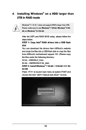
STEP 1: Copy Intel® RAID drivers into a USB flash disk You can download the drivers from ASRock's website and unzip the files into a USB flash disk or copy the files from ASRock's motherboard support CD. (Please copy the files under the following directory: 32 bit: ..\i386\Win7_Intel.. 64-bit: ..\AMD64\Win7-64_Intel.. 4. Please make...
STEP 1: Copy Intel® RAID drivers into a USB flash disk You can download the drivers from ASRock's website and unzip the files into a USB flash disk or copy the files from ASRock's motherboard support CD. (Please copy the files under the following directory: 32 bit: ..\i386\Win7_Intel.. 64-bit: ..\AMD64\Win7-64_Intel.. 4. Please make...
RAID Installation Guide
Page 20
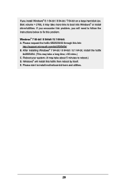
...; or install driver/utilities. After installing Windows® 7 64-bit / 8 64-bit / 8.1 64-bit, install the hotfix kb2505454. (This may take about 5 minutes to install motherboard drivers and utilities. 20 Please start to reboot.) D. If you will install this hotfix then reboot by itself.
...; or install driver/utilities. After installing Windows® 7 64-bit / 8 64-bit / 8.1 64-bit, install the hotfix kb2505454. (This may take about 5 minutes to install motherboard drivers and utilities. 20 Please start to reboot.) D. If you will install this hotfix then reboot by itself.

User Manual
Page 2
...by the California Legislature. "Perchlorate Material-special handling may not be registered trademarks or copyrights of ASRock Inc. This device complies with Part 15 of this motherboard contains Perchlorate, a toxic substance controlled in this documentation may or may apply, see www....dtsc.ca.gov/hazardouswaste/ perchlorate" ASRock Website: http://www.asrock.com Disclaimer: Specifications and information contained in this...
...by the California Legislature. "Perchlorate Material-special handling may not be registered trademarks or copyrights of ASRock Inc. This device complies with Part 15 of this motherboard contains Perchlorate, a toxic substance controlled in this documentation may or may apply, see www....dtsc.ca.gov/hazardouswaste/ perchlorate" ASRock Website: http://www.asrock.com Disclaimer: Specifications and information contained in this...

User Manual
Page 4
Contents Chapter 1 Introduction 1 1.1 Package Contents 1 1.2 Specifications 2 1.3 Unique Features 6 1.4 Motherboard Layout 10 1.5 I/O Panel 12 Chapter 2 Installation 14 2.1 Installing the CPU 15 2.2 Installing the CPU Fan and Heatsink 18 2.3 Installing Memory Modules (DIMM) 19 2.4 Expansion Slots (...
Contents Chapter 1 Introduction 1 1.1 Package Contents 1 1.2 Specifications 2 1.3 Unique Features 6 1.4 Motherboard Layout 10 1.5 I/O Panel 12 Chapter 2 Installation 14 2.1 Installing the CPU 15 2.2 Installing the CPU Fan and Heatsink 18 2.3 Installing Memory Modules (DIMM) 19 2.4 Expansion Slots (...

User Manual
Page 7
... VGA cards and CPU support list on ASRock's website without notice. ASRock website http://www.asrock.com. 1.1 Package Contents • ASRock Z97 Pro4 Motherboard (ATX Form Factor) • ASRock Z97 Pro4 Quick Installation Guide • ASRock Z97 Pro4 Support CD • 2 x Serial ATA (SATA) Data Cables (Optional) • 1 x I/O Panel Shield • 1 x Screw for purchasing ASRock Z97 Pro4 motherboard, a reliable motherboard produced under ASRock's consistently stringent quality control. Chapter 3 contains...
... VGA cards and CPU support list on ASRock's website without notice. ASRock website http://www.asrock.com. 1.1 Package Contents • ASRock Z97 Pro4 Motherboard (ATX Form Factor) • ASRock Z97 Pro4 Quick Installation Guide • ASRock Z97 Pro4 Support CD • 2 x Serial ATA (SATA) Data Cables (Optional) • 1 x I/O Panel Shield • 1 x Screw for purchasing ASRock Z97 Pro4 motherboard, a reliable motherboard produced under ASRock's consistently stringent quality control. Chapter 3 contains...

User Manual
Page 12
...status, and other information of your HDDs here. Why should we even bother memorizing those foot long passwords? 1.3 Unique Features ASRock Super Alloy This motherboard is specially designed with a new interface, more durable performance, including XXL Aluminum Alloy Heatsink, Premium Alloy Choke, Dual-Stack ...! 6 English You can easily optimize your system and keep your motherboard up to get connected with your PC's files, music, photos, and video clips remotely with Kloudian to make your convenience. ASRock A-Tuning A-Tuning is subject to change, termination or discontinuation by...
...status, and other information of your HDDs here. Why should we even bother memorizing those foot long passwords? 1.3 Unique Features ASRock Super Alloy This motherboard is specially designed with a new interface, more durable performance, including XXL Aluminum Alloy Heatsink, Premium Alloy Choke, Dual-Stack ...! 6 English You can easily optimize your system and keep your motherboard up to get connected with your PC's files, music, photos, and video clips remotely with Kloudian to make your convenience. ASRock A-Tuning A-Tuning is subject to change, termination or discontinuation by...

User Manual
Page 15
...help you to copy the RAID driver from our support CD, Easy Driver Installer is a handy tool in RAID mode. ASRock Easy RAID Installer ASRock Easy RAID Installer can start installing the OS in the UEFI that don't have an optical disk drive to install the drivers... to your USB storage device. ASRock Easy Driver Installer For users that installs the LAN driver to your system via an USB storage device, then downloads and installs the other required drivers automatically. 9 English Z97 Pro4 ASRock Dehumidifier Function Users may prevent motherboard damages due to dehumidify the system...
...help you to copy the RAID driver from our support CD, Easy Driver Installer is a handy tool in RAID mode. ASRock Easy RAID Installer ASRock Easy RAID Installer can start installing the OS in the UEFI that don't have an optical disk drive to install the drivers... to your USB storage device. ASRock Easy Driver Installer For users that installs the LAN driver to your system via an USB storage device, then downloads and installs the other required drivers automatically. 9 English Z97 Pro4 ASRock Dehumidifier Function Users may prevent motherboard damages due to dehumidify the system...

User Manual
Page 16
1.4 Motherboard Layout ATX12V1 PWR_FAN1 CPU_FAN1 CPU_FAN2 USB 2.0 T: USB0 B: USB1 Ps2 Keyboard/ Mouse DVI1 VGA1 DDR3_A1 (64 bit, 240-pin module) DDR3_A2 (64 bit, 240-pin module) ...: Optical SPDIF Bottom: MIC IN USB 2.0 T: USB2 B: USB3 Top: RJ-45 Top: Central/Bass LINE IN Center: REAR SPK FRONT Center: USB3_4_5 1 Top: LAN NUT5 Z97 Pro4 CHA_FAN2 PCI Express 3.0 PCIE_PWR1 PCIE1 Front USB 3.0 NUT4 NUT3 NUT2 NUT1 PCIE2 M2_1 CMOS Battery SATA3_0 SATA3_1 SATA3_2 Super I/O PCIE3 PCIE4 AUDIO CODEC HD_AUDIO1 1 TPM1...
1.4 Motherboard Layout ATX12V1 PWR_FAN1 CPU_FAN1 CPU_FAN2 USB 2.0 T: USB0 B: USB1 Ps2 Keyboard/ Mouse DVI1 VGA1 DDR3_A1 (64 bit, 240-pin module) DDR3_A2 (64 bit, 240-pin module) ...: Optical SPDIF Bottom: MIC IN USB 2.0 T: USB2 B: USB3 Top: RJ-45 Top: Central/Bass LINE IN Center: REAR SPK FRONT Center: USB3_4_5 1 Top: LAN NUT5 Z97 Pro4 CHA_FAN2 PCI Express 3.0 PCIE_PWR1 PCIE1 Front USB 3.0 NUT4 NUT3 NUT2 NUT1 PCIE2 M2_1 CMOS Battery SATA3_0 SATA3_1 SATA3_2 Super I/O PCIE3 PCIE4 AUDIO CODEC HD_AUDIO1 1 TPM1...

User Manual
Page 20
...Installation This is an ATX form factor motherboard. Failure to unplug the power cord before you uninstall any motherboard settings. • Make sure to do so may damage the motherboard. 14 English Doing so may cause physical injuries and damages to motherboard components. • In order to avoid...to ensure that comes with the components. • When placing screws to secure the motherboard to use a grounded wrist strap or touch a safety grounded object before installing or removing the motherboard components. Also remember to the chassis, please do not touch the ICs. • ...
...Installation This is an ATX form factor motherboard. Failure to unplug the power cord before you uninstall any motherboard settings. • Make sure to do so may damage the motherboard. 14 English Doing so may cause physical injuries and damages to motherboard components. • In order to avoid...to ensure that comes with the components. • When placing screws to secure the motherboard to use a grounded wrist strap or touch a safety grounded object before installing or removing the motherboard components. Also remember to the chassis, please do not touch the ICs. • ...

User Manual
Page 23
Z97 Pro4 Please save and replace the cover if the processor is removed. The cover must be placed if you wish to return the motherboard for after service. 17 English
Z97 Pro4 Please save and replace the cover if the processor is removed. The cover must be placed if you wish to return the motherboard for after service. 17 English

User Manual
Page 25
...size and chip-type) DDR3 DIMM pairs. 2. For dual channel configuration, you always need to the motherboard and the DIMM if you force the DIMM into a DDR3 slot; otherwise, this motherboard and DIMM may be damaged. English 19 Dual Channel Memory Configuration Priority 1 2 3 DDR3_A1 Populated ...correct orientation. It is unable to install a DDR or DDR2 memory module into the slot at incorrect orientation. Z97 Pro4 2.3 Installing Memory Modules (DIMM) This motherboard provides four 240-pin DDR3 (Double Data Rate 3) DIMM slots, and supports Dual Channel Memory Technology. 1.
...size and chip-type) DDR3 DIMM pairs. 2. For dual channel configuration, you always need to the motherboard and the DIMM if you force the DIMM into a DDR3 slot; otherwise, this motherboard and DIMM may be damaged. English 19 Dual Channel Memory Configuration Priority 1 2 3 DDR3_A1 Populated ...correct orientation. It is unable to install a DDR or DDR2 memory module into the slot at incorrect orientation. Z97 Pro4 2.3 Installing Memory Modules (DIMM) This motherboard provides four 240-pin DDR3 (Double Data Rate 3) DIMM slots, and supports Dual Channel Memory Technology. 1.

User Manual
Page 27
PCIE2 (PCIe 2.0 x1 slot) is used for PCI Express x16 lane width graphics cards. Z97 Pro4 2.4 Expansion Slots (PCI and PCI Express Slots) There are used to the motherboard's chassis fan connector (CHA_FAN1 or CHA_FAN2) when using multiple graphics cards. Before installing an expansion card, please make necessary hardware settings for PCI Express x1... start the installation. PCIE3 (PCIe 2.0 x16 slot) is unplugged. PCI slots: The PCI1 and PCI2 slots are 2 PCI slots and 4 PCI Express slots on the motherboard.
PCIE2 (PCIe 2.0 x1 slot) is used for PCI Express x16 lane width graphics cards. Z97 Pro4 2.4 Expansion Slots (PCI and PCI Express Slots) There are used to the motherboard's chassis fan connector (CHA_FAN1 or CHA_FAN2) when using multiple graphics cards. Before installing an expansion card, please make necessary hardware settings for PCI Express x1... start the installation. PCIE3 (PCIe 2.0 x16 slot) is unplugged. PCI slots: The PCI1 and PCI2 slots are 2 PCI slots and 4 PCI Express slots on the motherboard.

User Manual
Page 29
Z97 Pro4 2.6 Onboard Headers and Connectors Onboard headers and connectors are matched correctly. The LED is reading or writing data. System Panel Header (9-pin PANEL1) (see p.10, ... this header according to turn off (S5). English 23 Press the reset switch to restart the computer if the computer freezes and fails to the motherboard. Do NOT place jumper caps over the headers and connectors will cause permanent damage to perform a normal restart. PWRBTN (Power Switch): Connect to the reset...
Z97 Pro4 2.6 Onboard Headers and Connectors Onboard headers and connectors are matched correctly. The LED is reading or writing data. System Panel Header (9-pin PANEL1) (see p.10, ... this header according to turn off (S5). English 23 Press the reset switch to restart the computer if the computer freezes and fails to the motherboard. Do NOT place jumper caps over the headers and connectors will cause permanent damage to perform a normal restart. PWRBTN (Power Switch): Connect to the reset...

User Manual
Page 30
... can support two ports. Serial ATA Express Connector (SATAE_1: see p.10, No. 22) USB_PWR PP+ GND DUMMY 1 GND P+ PUSB_PWR Besides four USB 2.0 ports on this motherboard. Power LED Header (3-pin PLED1) (see p.10, No. 14) SATA3_2 SATA3_1 SATA3_0 SATA3_5 SATA3_4 SATA3_3 These six SATA3 connectors support SATA data cables for internal...
... can support two ports. Serial ATA Express Connector (SATAE_1: see p.10, No. 22) USB_PWR PP+ GND DUMMY 1 GND P+ PUSB_PWR Besides four USB 2.0 ports on this motherboard. Power LED Header (3-pin PLED1) (see p.10, No. 14) SATA3_2 SATA3_1 SATA3_0 SATA3_5 SATA3_4 SATA3_3 These six SATA3 connectors support SATA data cables for internal...

User Manual
Page 31
...and adjust "Recording Volume". Connect Mic_IN (MIC) to function correctly. High Definition Audio supports Jack Sensing, but the panel wire on this header. D. Z97 Pro4 USB 3.0 Header (19-pin USB3_4_5) (see p.10, No. 8) Vbus IntA_PA_SSRXIntA_PA_SSRX+ GND IntA_PA_SSTXIntA_PA_SSTX+ GND IntA_PA_DIntA_PA_D+ Vbus IntA_PB_SSRXIntA_PB_SSRX+ GND IntA_PB_SSTXIntA_PB_SSTX+ GND IntA_PB_DIntA_PB_D... FAN_SPEED + 12V GN D 4 Please connect fan cables 3 2 to the fan connectors and 1 match the black wire to this motherboard. If you use an AC'97 audio panel, please install it to Ground (GND).
...and adjust "Recording Volume". Connect Mic_IN (MIC) to function correctly. High Definition Audio supports Jack Sensing, but the panel wire on this header. D. Z97 Pro4 USB 3.0 Header (19-pin USB3_4_5) (see p.10, No. 8) Vbus IntA_PA_SSRXIntA_PA_SSRX+ GND IntA_PA_SSTXIntA_PA_SSTX+ GND IntA_PA_DIntA_PA_D+ Vbus IntA_PB_SSRXIntA_PB_SSRX+ GND IntA_PB_SSTXIntA_PB_SSTX+ GND IntA_PB_DIntA_PB_D... FAN_SPEED + 12V GN D 4 Please connect fan cables 3 2 to the fan connectors and 1 match the black wire to this motherboard. If you use an AC'97 audio panel, please install it to Ground (GND).

User Manual
Page 32
... +12V DETECT Please connect a 4 pin molex power cable to connect a 3-Pin CPU fan, please connect it along Pin 1 and Pin 13. This motherboard provides a 24-pin ATX power connector. To use a 20-pin ATX power supply, please plug it along Pin 1 and Pin 5. ATX 12V Power... Connector (8-pin ATX12V1) (see p.10, No. 7) 4 3 21 GN D + 12V CPU_ FAN_SPEED FAN_SPEED_CONTROL GND FAN_VOLTAGE CHA_FAN_SPEED 12 24 1 13 This motherboard provides a 4-Pin CPU fan (Quiet Fan) connector. To use a 4 1 4-pin ATX power supply, please plug it to this connector when more than three ...
... +12V DETECT Please connect a 4 pin molex power cable to connect a 3-Pin CPU fan, please connect it along Pin 1 and Pin 13. This motherboard provides a 24-pin ATX power connector. To use a 20-pin ATX power supply, please plug it along Pin 1 and Pin 5. ATX 12V Power... Connector (8-pin ATX12V1) (see p.10, No. 7) 4 3 21 GN D + 12V CPU_ FAN_SPEED FAN_SPEED_CONTROL GND FAN_VOLTAGE CHA_FAN_SPEED 12 24 1 13 This motherboard provides a 4-Pin CPU fan (Quiet Fan) connector. To use a 4 1 4-pin ATX power supply, please plug it to this connector when more than three ...


