
Intel Smart Response Installation Guide
Page 1
... update the new version RST driver in RAID ROM. For the new version RST driver, please check our website for the latest information: http://www.asrock.com * Before you just need to set the UEFI option "SATA Mode" to [RAID Mode]. Intel Smart Response Technology Installation Guide This...
... update the new version RST driver in RAID ROM. For the new version RST driver, please check our website for the latest information: http://www.asrock.com * Before you just need to set the UEFI option "SATA Mode" to [RAID Mode]. Intel Smart Response Technology Installation Guide This...
User Manual
Page 2
...rights reserved. "Perchlorate Material-special handling may cause undesired operation. With respect to the implied warranties or conditions of this motherboard contains Perchlorate, a toxic substance controlled in this documentation may be liable for any indirect, special, incidental, or consequential...appearing in this documentation may or may appear in Perchlorate Best Management Practices (BMP) regulations passed by ASRock. ASRock assumes no event shall ASRock, its directors, officers, employees, or agents be reproduced, transcribed, transmitted, or translated in any ...
...rights reserved. "Perchlorate Material-special handling may cause undesired operation. With respect to the implied warranties or conditions of this motherboard contains Perchlorate, a toxic substance controlled in this documentation may be liable for any indirect, special, incidental, or consequential...appearing in this documentation may or may appear in Perchlorate Best Management Practices (BMP) regulations passed by ASRock. ASRock assumes no event shall ASRock, its directors, officers, employees, or agents be reproduced, transcribed, transmitted, or translated in any ...
User Manual
Page 4
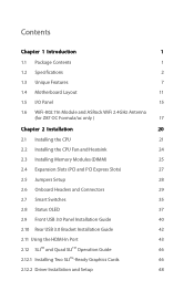
Contents Chapter 1 Introduction 1 1.1 Package Contents 1 1.2 Specifications 2 1.3 Unique Features 7 1.4 Motherboard Layout 11 1.5 I/O Panel 15 1.6 WiFi-802.11n Module and ASRock WiFi 2.4GHz Antenna (for Z87 OC Formula/ac only ) 17 Chapter 2 Installation 20 2.1 Installing the CPU 21 2.2 Installing the CPU Fan and Heatsink 24 2.3 Installing Memory Modules (DIMM) 25 2.4 Expansion Slots (PCI and ...
Contents Chapter 1 Introduction 1 1.1 Package Contents 1 1.2 Specifications 2 1.3 Unique Features 7 1.4 Motherboard Layout 11 1.5 I/O Panel 15 1.6 WiFi-802.11n Module and ASRock WiFi 2.4GHz Antenna (for Z87 OC Formula/ac only ) 17 Chapter 2 Installation 20 2.1 Installing the CPU 21 2.2 Installing the CPU Fan and Heatsink 24 2.3 Installing Memory Modules (DIMM) 25 2.4 Expansion Slots (PCI and ...
User Manual
Page 7
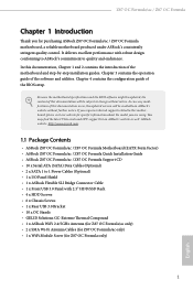
... require technical support related to this documentation occur, the updated version will be subject to quality and endurance. ASRock website http://www.asrock.com. 1.1 Package Contents • ASRock Z87 OC Formula/ac / Z87 OC Formula Motherboard (EATX Form Factor) • ASRock Z87 OC Formula/ac / Z87 OC Formula Quick Installation Guide • ASRock Z87 OC Formula/ac / Z87 OC Formula Support CD • 10 x Serial ATA (SATA) Data Cables (Optional) • 2 x SATA 1 to 1 Power Cables (Optional) •...
... require technical support related to this documentation occur, the updated version will be subject to quality and endurance. ASRock website http://www.asrock.com. 1.1 Package Contents • ASRock Z87 OC Formula/ac / Z87 OC Formula Motherboard (EATX Form Factor) • ASRock Z87 OC Formula/ac / Z87 OC Formula Quick Installation Guide • ASRock Z87 OC Formula/ac / Z87 OC Formula Support CD • 10 x Serial ATA (SATA) Data Cables (Optional) • 2 x SATA 1 to 1 Power Cables (Optional) •...
User Manual
Page 14
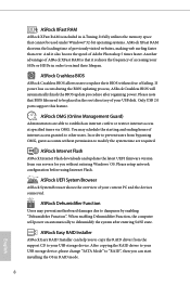
... may schedule the starting and ending hours of internet access granted to update their lifespan. ASRock Crashless BIOS ASRock Crashless BIOS allows users to other users. You may prevent motherboard damages due to establish an internet curfew or restrict internet access at specified times via OMG... permission to your USB storage device, please change "SATA Mode" to extend their BIOS without entering Windows® OS. ASRock Easy RAID Installer ASRock Easy RAID Installer can start installing the OS in A-Tuning. After copying the RAID driver to your USB storage device. Another...
... may schedule the starting and ending hours of internet access granted to update their lifespan. ASRock Crashless BIOS ASRock Crashless BIOS allows users to other users. You may prevent motherboard damages due to establish an internet curfew or restrict internet access at specified times via OMG... permission to your USB storage device, please change "SATA Mode" to extend their BIOS without entering Windows® OS. ASRock Easy RAID Installer ASRock Easy RAID Installer can start installing the OS in A-Tuning. After copying the RAID driver to your USB storage device. Another...
User Manual
Page 15
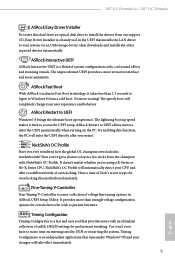
... waiting! Timing Configurator Timing Configurator is a fast and easy tool that installs the LAN driver to access the UEFI setup. Z87 OC Formula/ac / Z87 OC Formula ASRock Easy Driver Installer For users that don't have to learn a few tricks from the champion with an abundant collection of subtle...doesn't matter whether you're using a K-Series or No-K Series CPU, NickShih's OC Profile will completely change your CPU and offer you ever wondered how the global OC champion overclocks his motherboards? It provides more than 1.5 seconds to logon to UEFI Windows® 8 brings...
... waiting! Timing Configurator Timing Configurator is a fast and easy tool that installs the LAN driver to access the UEFI setup. Z87 OC Formula/ac / Z87 OC Formula ASRock Easy Driver Installer For users that don't have to learn a few tricks from the champion with an abundant collection of subtle...doesn't matter whether you're using a K-Series or No-K Series CPU, NickShih's OC Profile will completely change your CPU and offer you ever wondered how the global OC champion overclocks his motherboards? It provides more than 1.5 seconds to logon to UEFI Windows® 8 brings...
User Manual
Page 16
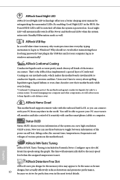
... In a world where time is powered on the motherboard. Why should we still advise users to power your PC on or turn it remotely with your PC from anywhere in Formula Drive. ASRock Conformal Coating Conductive liquids such as water pretty much destroy all kinds of the system on a new high ... implemented a special layer of it off, monitor and take control of Conformal Coating on contact. ASRock Home Cloud This motherboard supports remote wake with the onboard Intel LAN, so you a better sleeping environment by extinguishing the unessential LEDs. By enabling Good Night LED in...
... In a world where time is powered on the motherboard. Why should we still advise users to power your PC on or turn it remotely with your PC from anywhere in Formula Drive. ASRock Conformal Coating Conductive liquids such as water pretty much destroy all kinds of the system on a new high ... implemented a special layer of it off, monitor and take control of Conformal Coating on contact. ASRock Home Cloud This motherboard supports remote wake with the onboard Intel LAN, so you a better sleeping environment by extinguishing the unessential LEDs. By enabling Good Night LED in...
User Manual
Page 17
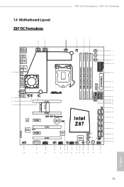
Z87 OC Formula/ac / Z87 OC Formula 1.4 Motherboard Layout Z87 OC Formula/ac 1 2 3 4 5 6 HDMI2 USB 3.0 T: USB0 B: USB1 HDMI1 USB 3.0 T: USB2 Top: RJ-45 B: USB3 44 USB 2.0 T: USB0 B: USB1 PS2 Keyboard /Mouse ATX12V1 ATX12V3 CPU_FAN1 CPU_FAN2 + 7 -... ON ON USB3_12 USB3_10_11 USB3_8_9 LN2MODE1 CHA_FAN3 12 13 14 15 16 17 18 19 WiFi-802.11n Module MINI_PCIE1 20 PCIE2 Z87 OC Formula Intel 21 LAN PCIE3 CMOS CLRCMOS1 Battery 1 Z87 22 Purity RoHS SoundTM PCIE5 PCIE4 HD_AUDIO1 1 SLI/XFIRE_PWR1 PCIE6 COM1 1 Super I/O CHA_FAN1 USB4_5 1 CHA_FAN2 USB2_3 1 Status...
Z87 OC Formula/ac / Z87 OC Formula 1.4 Motherboard Layout Z87 OC Formula/ac 1 2 3 4 5 6 HDMI2 USB 3.0 T: USB0 B: USB1 HDMI1 USB 3.0 T: USB2 Top: RJ-45 B: USB3 44 USB 2.0 T: USB0 B: USB1 PS2 Keyboard /Mouse ATX12V1 ATX12V3 CPU_FAN1 CPU_FAN2 + 7 -... ON ON USB3_12 USB3_10_11 USB3_8_9 LN2MODE1 CHA_FAN3 12 13 14 15 16 17 18 19 WiFi-802.11n Module MINI_PCIE1 20 PCIE2 Z87 OC Formula Intel 21 LAN PCIE3 CMOS CLRCMOS1 Battery 1 Z87 22 Purity RoHS SoundTM PCIE5 PCIE4 HD_AUDIO1 1 SLI/XFIRE_PWR1 PCIE6 COM1 1 Super I/O CHA_FAN1 USB4_5 1 CHA_FAN2 USB2_3 1 Status...

User Manual
Page 23
... v4.0. WiFi + BT module is supported under Windows® 8 / 8 64-bit / 7 / 7 64-bit only. Z87 OC Formula/ac / Z87 OC Formula 1.6 WiFi-802.11n Module and ASRock WiFi 2.4GHz Antenna (for Z87 OC Formula/ac only ) WiFi + BT Module This motherboard comes with an exclusive WiFi 802.11 a/b/g/n/ac + BT v4.0 module that adds a whole new class of functionality into the mobile devices including...
... v4.0. WiFi + BT module is supported under Windows® 8 / 8 64-bit / 7 / 7 64-bit only. Z87 OC Formula/ac / Z87 OC Formula 1.6 WiFi-802.11n Module and ASRock WiFi 2.4GHz Antenna (for Z87 OC Formula/ac only ) WiFi + BT Module This motherboard comes with an exclusive WiFi 802.11 a/b/g/n/ac + BT v4.0 module that adds a whole new class of functionality into the mobile devices including...
User Manual
Page 24
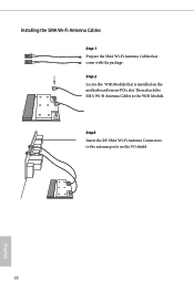
Then attach the SMA Wi-Fi Antenna Cables to the antenna ports on the motherboard's mini-PCIe slot. Step 2 Locate the WiFi Module that come with the package. Installing the SMA Wi-Fi Antenna Cables Step 1 Prepare the SMA Wi-Fi Antenna Cables that is installed on the I/O shield 18 English Step3 Insert the RP-SMA Wi-Fi Antenna Connectors to the WiFi Module.
Then attach the SMA Wi-Fi Antenna Cables to the antenna ports on the motherboard's mini-PCIe slot. Step 2 Locate the WiFi Module that come with the package. Installing the SMA Wi-Fi Antenna Cables Step 1 Prepare the SMA Wi-Fi Antenna Cables that is installed on the I/O shield 18 English Step3 Insert the RP-SMA Wi-Fi Antenna Connectors to the WiFi Module.
User Manual
Page 26
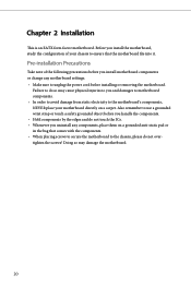
...grounded wrist strap or touch a safety grounded object before installing or removing the motherboard. Before you install the motherboard, study the configuration of the following precautions before you and damages to motherboard components. • In order to avoid damage from static electricity to unplug ... Hold components by the edges and do not touch the ICs. • Whenever you uninstall any motherboard settings. • Make sure to the motherboard's components, NEVER place your motherboard directly on a grounded anti-static pad or in the bag that comes with the components. •...
...grounded wrist strap or touch a safety grounded object before installing or removing the motherboard. Before you install the motherboard, study the configuration of the following precautions before you and damages to motherboard components. • In order to avoid damage from static electricity to unplug ... Hold components by the edges and do not touch the ICs. • Whenever you uninstall any motherboard settings. • Make sure to the motherboard's components, NEVER place your motherboard directly on a grounded anti-static pad or in the bag that comes with the components. •...
User Manual
Page 29
The cover must be placed if you wish to return the motherboard for after service. 23 English Z87 OC Formula/ac / Z87 OC Formula Please save and replace the cover if the processor is removed.
The cover must be placed if you wish to return the motherboard for after service. 23 English Z87 OC Formula/ac / Z87 OC Formula Please save and replace the cover if the processor is removed.
User Manual
Page 31
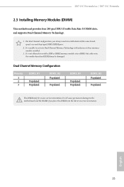
... memory module into the slot at incorrect orientation. For dual channel configuration, you always need to the motherboard and the DIMM if you force the DIMM into a DDR3 slot; Z87 OC Formula/ac / Z87 OC Formula 2.3 Installing Memory Modules (DIMM) This motherboard provides four 240-pin DDR3 (Double Data Rate 3) DIMM slots, and supports Dual Channel Memory Technology. 1. otherwise...
... memory module into the slot at incorrect orientation. For dual channel configuration, you always need to the motherboard and the DIMM if you force the DIMM into a DDR3 slot; Z87 OC Formula/ac / Z87 OC Formula 2.3 Installing Memory Modules (DIMM) This motherboard provides four 240-pin DDR3 (Double Data Rate 3) DIMM slots, and supports Dual Channel Memory Technology. 1. otherwise...
User Manual
Page 33
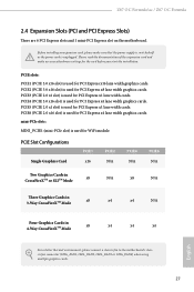
.... PCIE3 (PCIE 2.0 x1 slot) is used for PCI Express x1 lane width cards. Z87 OC Formula/ac / Z87 OC Formula 2.4 Expansion Slots (PCI and PCI Express Slots) There are 6 PCI Express slots and 1 mini-PCI Express slot on the motherboard. PCIE slots: PCIE1 (PCIE 3.0 x16 slot) is unplugged. Before installing an expansion card...Graphics Cards in 4-Way CrossFireXTM Mode x8 x4 x4 x4 English For a better thermal environment, please connect a chassis fan to the motherboard's chassis fan connector (CHA_FAN1, CHA_FAN2, CHA_FAN3 or CHA_FAN4) when using multiple graphics cards. 27
.... PCIE3 (PCIE 2.0 x1 slot) is used for PCI Express x1 lane width cards. Z87 OC Formula/ac / Z87 OC Formula 2.4 Expansion Slots (PCI and PCI Express Slots) There are 6 PCI Express slots and 1 mini-PCI Express slot on the motherboard. PCIE slots: PCIE1 (PCIE 3.0 x16 slot) is unplugged. Before installing an expansion card...Graphics Cards in 4-Way CrossFireXTM Mode x8 x4 x4 x4 English For a better thermal environment, please connect a chassis fan to the motherboard's chassis fan connector (CHA_FAN1, CHA_FAN2, CHA_FAN3 or CHA_FAN4) when using multiple graphics cards. 27
User Manual
Page 35
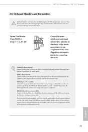
... to the power status indicator on the chassis front panel. English 29 Z87 OC Formula/ac / Z87 OC Formula 2.6 Onboard Headers and Connectors Onboard headers and connectors are matched correctly. The LED is off your chassis front panel module to this header according to the motherboard. Do NOT place jumper caps over the headers and connectors will cause...
... to the power status indicator on the chassis front panel. English 29 Z87 OC Formula/ac / Z87 OC Formula 2.6 Onboard Headers and Connectors Onboard headers and connectors are matched correctly. The LED is off your chassis front panel module to this header according to the motherboard. Do NOT place jumper caps over the headers and connectors will cause...
User Manual
Page 36
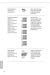
SATA3_A3_A4 SATA3_A1_A2 SATA3_0_1 SATA3_2_3 SATA3_4_5 Power LED Header (3-pin PLED1) (see p.11 or 12, No. 20) Please connect the chassis power LED to this motherboard. USB 2.0 Headers (9-pin USB2_3) (see p.11 or 12, No. 33) (9-pin USB4_5) (see p.11 or 12, No. 36) USB_PWR PP+ GND DUMMY 1 ...SATA data cables for your bootable devices. Each USB 2.0 header can support two ports. 30 English To minimize the boot time, use Intel® Z87 SATA ports (SATA3_0) for internal storage devices with up to indicate the system's power status. PLED+ PLED+ Serial ATA3 Connectors (SATA3_0_1: see p....
SATA3_A3_A4 SATA3_A1_A2 SATA3_0_1 SATA3_2_3 SATA3_4_5 Power LED Header (3-pin PLED1) (see p.11 or 12, No. 20) Please connect the chassis power LED to this motherboard. USB 2.0 Headers (9-pin USB2_3) (see p.11 or 12, No. 33) (9-pin USB4_5) (see p.11 or 12, No. 36) USB_PWR PP+ GND DUMMY 1 ...SATA data cables for your bootable devices. Each USB 2.0 header can support two ports. 30 English To minimize the boot time, use Intel® Z87 SATA ports (SATA3_0) for internal storage devices with up to indicate the system's power status. PLED+ PLED+ Serial ATA3 Connectors (SATA3_0_1: see p....
User Manual
Page 37
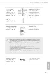
... audio panel. C. You don't need to the front panel audio header by the steps below: A. English 31 Z87 OC Formula/ac / Z87 OC Formula USB 3.0 Headers (19-pin USB3_8_9) (see p.11 or 12, No. 15) (19-pin USB3_10_11) (see p.11 or 12, No. 16) (USB3_12) (see p.11 or 12, ... Ground (GND). Front Panel Audio Header (9-pin HD_AUDIO1) (see p.11 or 12, No. 25) DUMMY SPEAKER 1 +5V DUMMY Please connect the chassis speaker to this motherboard. E. Connect Ground (GND) to install your system. 2.
... audio panel. C. You don't need to the front panel audio header by the steps below: A. English 31 Z87 OC Formula/ac / Z87 OC Formula USB 3.0 Headers (19-pin USB3_8_9) (see p.11 or 12, No. 15) (19-pin USB3_10_11) (see p.11 or 12, No. 16) (USB3_12) (see p.11 or 12, ... Ground (GND). Front Panel Audio Header (9-pin HD_AUDIO1) (see p.11 or 12, No. 25) DUMMY SPEAKER 1 +5V DUMMY Please connect the chassis speaker to this motherboard. E. Connect Ground (GND) to install your system. 2.

User Manual
Page 38
... Connectors (4-pin CPU_FAN1) (see p.11 or 12, No. 3) (3-pin CPU_FAN2) (see p.11 or 12, No. 4) 4 3 21 GN D + 12V CPU_ FAN_SPEED FAN_SPEED_CONTROL GND +12V CPU_FAN_SPEED This motherboard provides a 4-Pin CPU fan (Quiet Fan) connector. If you plan to connect a 3-Pin CPU fan, please connect it along Pin 1 and Pin 13. Chassis, Power... and match the black wire to Pin 1-3. English ATX Power Connector (24-pin ATXPWR1) (see p.11 or 12, No. 12) 32 12 24 1 13 This motherboard provides a 24-pin ATX power connector.
... Connectors (4-pin CPU_FAN1) (see p.11 or 12, No. 3) (3-pin CPU_FAN2) (see p.11 or 12, No. 4) 4 3 21 GN D + 12V CPU_ FAN_SPEED FAN_SPEED_CONTROL GND +12V CPU_FAN_SPEED This motherboard provides a 4-Pin CPU fan (Quiet Fan) connector. If you plan to connect a 3-Pin CPU fan, please connect it along Pin 1 and Pin 13. Chassis, Power... and match the black wire to Pin 1-3. English ATX Power Connector (24-pin ATXPWR1) (see p.11 or 12, No. 12) 32 12 24 1 13 This motherboard provides a 24-pin ATX power connector.
User Manual
Page 39
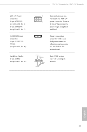
...#1 RRTS#1 GND TTXD1 DDCD#1 Please connect this connector with a hard disk power connector when two graphics cards are installed on this motherboard. English 33 vides an 8-pin ATX 12V 4 1 power connector. Z87 OC Formula/ac / Z87 OC Formula ATX 12V Power Connector (8-pin ATX12V1) (see p.11 or 12, No. 1) (8-pin ATX12V3) (see p.11 or 12, No. 2) SLI/XFIRE...
...#1 RRTS#1 GND TTXD1 DDCD#1 Please connect this connector with a hard disk power connector when two graphics cards are installed on this motherboard. English 33 vides an 8-pin ATX 12V 4 1 power connector. Z87 OC Formula/ac / Z87 OC Formula ATX 12V Power Connector (8-pin ATX12V1) (see p.11 or 12, No. 1) (8-pin ATX12V3) (see p.11 or 12, No. 2) SLI/XFIRE...

User Manual
Page 41
...Menu Button (MENU1: see p.11 or 12, No. 30) Clear CMOS Switch allows users to quickly clear the CMOS values. Z87 OC Formula/ac / Z87 OC Formula 2.7 Smart Switches The motherboard has three smart switches: Power Switch, Reset Switch and Clear CMOS Switch, allowing users to quickly turn on/off the system, ...reset the system or clear the CMOS values. Rapid OC Buttons + (MINUS1: see p.11 or 12, No. 7) (PLUS1: see p.11 or 12, ...
...Menu Button (MENU1: see p.11 or 12, No. 30) Clear CMOS Switch allows users to quickly clear the CMOS values. Z87 OC Formula/ac / Z87 OC Formula 2.7 Smart Switches The motherboard has three smart switches: Power Switch, Reset Switch and Clear CMOS Switch, allowing users to quickly turn on/off the system, ...reset the system or clear the CMOS values. Rapid OC Buttons + (MINUS1: see p.11 or 12, No. 7) (PLUS1: see p.11 or 12, ...


