RAID Installation Guide
Page 1
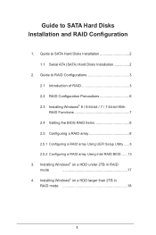
... RAID 3 2.2 RAID Configuration Precautions 6 2.3 Installing Windows® 8 / 8 64-bit / 7 / 7 64-bit With RAID Functions 7 2.4 Setting the BIOS RAID Items 8 2.5 Configuring a RAID array 8 2.5.1 Configuring a RAID array Using UEFI Setup Utility....... 8 2.5.2 Configuring a RAID array Using Intel RAID BIOS....... 13 3. Installing Windows® on a HDD larger than 2TB in RAID mode 17 4. Guide to SATA...
... RAID 3 2.2 RAID Configuration Precautions 6 2.3 Installing Windows® 8 / 8 64-bit / 7 / 7 64-bit With RAID Functions 7 2.4 Setting the BIOS RAID Items 8 2.5 Configuring a RAID array 8 2.5.1 Configuring a RAID array Using UEFI Setup Utility....... 8 2.5.2 Configuring a RAID array Using Intel RAID BIOS....... 13 3. Installing Windows® on a HDD larger than 2TB in RAID mode 17 4. Guide to SATA...
RAID Installation Guide
Page 8
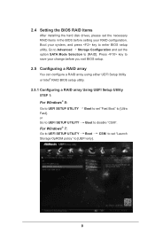
...please set "Fast Boot" to [Ultra Fast]. Press key to save your change before you exit BIOS setup. 2.5 Configuring a RAID array You can configure a RAID array using either UEFI Setup Utility or Intel® RAID BIOS setup utility. 2.5.1 Configuring a RAID array Using UEFI Setup Utility STEP 1: For Windows® 8: ...Go to UEFI SETUP UTILITY Boot to set the necessary RAID items in the BIOS before setting your system, and press key to disable "CSM". For Windows® 7: Go to UEFI SETUP UTILITY Boot CSM to set the option ...
...please set "Fast Boot" to [Ultra Fast]. Press key to save your change before you exit BIOS setup. 2.5 Configuring a RAID array You can configure a RAID array using either UEFI Setup Utility or Intel® RAID BIOS setup utility. 2.5.1 Configuring a RAID array Using UEFI Setup Utility STEP 1: For Windows® 8: ...Go to UEFI SETUP UTILITY Boot to set the necessary RAID items in the BIOS before setting your system, and press key to disable "CSM". For Windows® 7: Go to UEFI SETUP UTILITY Boot CSM to set the option ...
RAID Installation Guide
Page 13
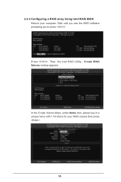
Press . Create RAID Volume window appears. Volume0 13 Then, the Intel RAID Utility - Wait until you see the RAID software prompting you to press . In the Create Volume Menu, under Name item, please key-in a unique name with 1-16 letters for your computer. 2.5.2 Configuring a RAID array Using Intel RAID BIOS Reboot your RAID volume then press .
Press . Create RAID Volume window appears. Volume0 13 Then, the Intel RAID Utility - Wait until you see the RAID software prompting you to press . In the Create Volume Menu, under Name item, please key-in a unique name with 1-16 letters for your computer. 2.5.2 Configuring a RAID array Using Intel RAID BIOS Reboot your RAID volume then press .

RAID Installation Guide
Page 16
If you are only allowed to create one RAID partition at a time under Windows environment to create an extra RAID partition, please use the RAID utility under BIOS RAID environment. Press to delete a RAID volume, please select the option Delete RAID Volume, press , and then follow the instructions on the screen. 16 Please note that you install OS. After the completion, you will see the detailed information about the RAID that you want to configure RAID functions after you set up. If you want to complete the setup of RAID.
If you are only allowed to create one RAID partition at a time under Windows environment to create an extra RAID partition, please use the RAID utility under BIOS RAID environment. Press to delete a RAID volume, please select the option Delete RAID Volume, press , and then follow the instructions on the screen. 16 Please note that you install OS. After the completion, you will see the detailed information about the RAID that you want to configure RAID functions after you set up. If you want to complete the setup of RAID.
RAID Installation Guide
Page 17
3. Installing Windows® on a HDD under 2TB in RAID mode After the UEFI and RAID BIOS setup you may start installing Windows® 8 / 8 64-bit / 7 / 7 64-bit OS as usual. 17
3. Installing Windows® on a HDD under 2TB in RAID mode After the UEFI and RAID BIOS setup you may start installing Windows® 8 / 8 64-bit / 7 / 7 64-bit OS as usual. 17
RAID Installation Guide
Page 18
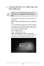
... Windows® on a HDD larger than 2TB in RAID mode Windows® 7 / 8 does not support HDD's larger than 2TB. After the UEFI and RAID BIOS setup, please follow the steps below. STEP 2: Install Windows® 7 64-bit / 8 64-bit OS Press to launch boot menu at system POST and choose...8 64-bit. STEP 1: Copy Intel® RAID drivers into a USB flash disk You can download the drivers from ASRock's website and unzip the files into a USB flash disk or copy the files from ASRock's motherboard support CD. (Please copy the files under the following directory: 32 bit: ..\i386\Win7_Intel.. 64-bit: ...
... Windows® on a HDD larger than 2TB in RAID mode Windows® 7 / 8 does not support HDD's larger than 2TB. After the UEFI and RAID BIOS setup, please follow the steps below. STEP 2: Install Windows® 7 64-bit / 8 64-bit OS Press to launch boot menu at system POST and choose...8 64-bit. STEP 1: Copy Intel® RAID drivers into a USB flash disk You can download the drivers from ASRock's website and unzip the files into a USB flash disk or copy the files from ASRock's motherboard support CD. (Please copy the files under the following directory: 32 bit: ..\i386\Win7_Intel.. 64-bit: ...

Intel Rapid Storage Guide
Page 12
... method) In order to install an operating system onto a RAID volume, the RAID option must be enabled in the system BIOS. 1. Click F2 or Delete to save the BIOS settings and exit the BIOS Setup program. Click the Storage Configuration menu. 4. Unless you have selected RAID 1, use the up or down arrow keys... to select the RAID level and press Enter. 4. When finished press Enter. 12 Click F10 to enter the BIOS Setup program after the Power-On-Self-Test (POST) memory test begins. 2. Use the up or down arrow keys to scroll through the list of...
... method) In order to install an operating system onto a RAID volume, the RAID option must be enabled in the system BIOS. 1. Click F2 or Delete to save the BIOS settings and exit the BIOS Setup program. Click the Storage Configuration menu. 4. Unless you have selected RAID 1, use the up or down arrow keys... to select the RAID level and press Enter. 4. When finished press Enter. 12 Click F10 to enter the BIOS Setup program after the Power-On-Self-Test (POST) memory test begins. 2. Use the up or down arrow keys to scroll through the list of...
User Manual
Page 7
Chapter 3 contains the operation guide of the BIOS setup. In case any modifications of this documentation occur, the updated version will be available on ASRock's website as well. ASRock website http://www.asrock.com. 1.1 Package Contents • ASRock Z87 Extreme6/ac / Z87 Extreme6 Motherboard (ATX Form Factor) • ASRock Z87 Extreme6/ac / Z87 Extreme6 Quick Installation Guide • ASRock Z87 Extreme6/ac / Z87 Extreme6 Support CD • 6 x Serial ATA (SATA) Data Cables (Optional...
Chapter 3 contains the operation guide of the BIOS setup. In case any modifications of this documentation occur, the updated version will be available on ASRock's website as well. ASRock website http://www.asrock.com. 1.1 Package Contents • ASRock Z87 Extreme6/ac / Z87 Extreme6 Motherboard (ATX Form Factor) • ASRock Z87 Extreme6/ac / Z87 Extreme6 Quick Installation Guide • ASRock Z87 Extreme6/ac / Z87 Extreme6 Support CD • 6 x Serial ATA (SATA) Data Cables (Optional...
User Manual
Page 11
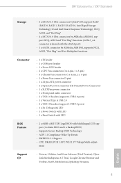
Z87 Extreme6/ac / Z87 Extreme6 Storage • 6 x SATA3 6.0 Gb/s connectors by Intel® Z87, support RAID (RAID 0, RAID 1, RAID 5, RAID 10, Intel Rapid Storage Technology 12 and Intel Smart Response Technology), NCQ, AHCI and "Hot Plug" ... • 1 x Dr. Debug with LED • 1 x Power Switch with LED • 1 x Reset Switch with LED BIOS Feature • 2 x 64Mb AMI UEFI Legal BIOS with Multilingual GUI support (1 x Main BIOS and 1 x Backup BIOS) • Supports Secure Backup UEFI Technology • ACPI 1.1 Compliance Wake Up Events • SMBIOS 2.3.1 Support • CPU, DRAM...
Z87 Extreme6/ac / Z87 Extreme6 Storage • 6 x SATA3 6.0 Gb/s connectors by Intel® Z87, support RAID (RAID 0, RAID 1, RAID 5, RAID 10, Intel Rapid Storage Technology 12 and Intel Smart Response Technology), NCQ, AHCI and "Hot Plug" ... • 1 x Dr. Debug with LED • 1 x Power Switch with LED • 1 x Reset Switch with LED BIOS Feature • 2 x 64Mb AMI UEFI Legal BIOS with Multilingual GUI support (1 x Main BIOS and 1 x Backup BIOS) • Supports Secure Backup UEFI Technology • ACPI 1.1 Compliance Wake Up Events • SMBIOS 2.3.1 Support • CPU, DRAM...

User Manual
Page 12
... WHQL • ErP/EuP Ready (ErP/EuP ready power supply is a certain risk involved with overclocking, including adjusting the setting in the BIOS, applying Untied Overclocking Technology, or using third-party overclocking tools. English 6 Overclocking may be done at your own risk and expense. Hardware ... Temperature Sensing • CPU/Chassis/Power Fan Tachometer • CPU/Chassis Quiet Fan (Allow Chassis Fan Speed Auto- You can use ASRock XFast RAM to the components and devices of your system's stability, or even cause damage to utilize the memory that there is required)...
... WHQL • ErP/EuP Ready (ErP/EuP ready power supply is a certain risk involved with overclocking, including adjusting the setting in the BIOS, applying Untied Overclocking Technology, or using third-party overclocking tools. English 6 Overclocking may be done at your own risk and expense. Hardware ... Temperature Sensing • CPU/Chassis/Power Fan Tachometer • CPU/Chassis Quiet Fan (Allow Chassis Fan Speed Auto- You can use ASRock XFast RAM to the components and devices of your system's stability, or even cause damage to utilize the memory that there is required)...
User Manual
Page 13
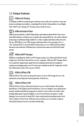
... supports continuous charging when your iPhone/iPad/iPod Touch charge up to access ASRock Instant Flash. Just save the new BIOS file to your USB storage and launch this tool by installing the ASRock APP Charger makes your PC enters into Standby mode (S1), Suspend to... ASRock APP Charger Simply by pressing or during POST to enter the BIOS setup menu to 40% faster than before on the properties of Your Data: With the status window, you can easily recognize which includes the benefits listed below. Z87 Extreme6/ac / Z87 Extreme6 1.3 Unique Features ASRock A-Tuning A-Tuning is a BIOS ...
... supports continuous charging when your iPhone/iPad/iPod Touch charge up to access ASRock Instant Flash. Just save the new BIOS file to your USB storage and launch this tool by installing the ASRock APP Charger makes your PC enters into Standby mode (S1), Suspend to... ASRock APP Charger Simply by pressing or during POST to enter the BIOS setup menu to 40% faster than before on the properties of Your Data: With the status window, you can easily recognize which includes the benefits listed below. Z87 Extreme6/ac / Z87 Extreme6 1.3 Unique Features ASRock A-Tuning A-Tuning is a BIOS ...
User Manual
Page 14
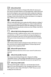
... required. You may prevent motherboard damages due to other users. ASRock UEFI System Browser ASRock System Browser shows the overview of your USB disk. ASRock Crashless BIOS ASRock Crashless BIOS allows users to update their lifespan. ASRock XFast RAM ASRock XFast RAM is that it also boosts the speed of Adobe ... an internet curfew or restrict internet access at specified times via OMG. If power loss occurs during the BIOS updating process, ASRock Crashless BIOS will power on automatically to copy the RAID driver from our servers for you to dehumidify the system after regaining...
... required. You may prevent motherboard damages due to other users. ASRock UEFI System Browser ASRock System Browser shows the overview of your USB disk. ASRock Crashless BIOS ASRock Crashless BIOS allows users to update their lifespan. ASRock XFast RAM ASRock XFast RAM is that it also boosts the speed of Adobe ... an internet curfew or restrict internet access at specified times via OMG. If power loss occurs during the BIOS updating process, ASRock Crashless BIOS will power on automatically to copy the RAID driver from our servers for you to dehumidify the system after regaining...
User Manual
Page 15
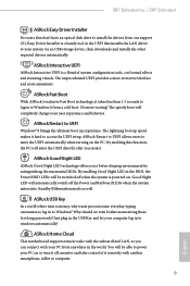
... Good Night LED in the BIOS, the Power/HDD LEDs will enter the UEFI directly after you restart. Why should we even bother memorizing those foot long passwords? You will automatically switch off , monitor and take control of system configuration tools, cool sound effects and stunning visuals. Z87 Extreme6/ac / Z87 Extreme6 ASRock Easy Driver Installer For...
... Good Night LED in the BIOS, the Power/HDD LEDs will enter the UEFI directly after you restart. Why should we even bother memorizing those foot long passwords? You will automatically switch off , monitor and take control of system configuration tools, cool sound effects and stunning visuals. Z87 Extreme6/ac / Z87 Extreme6 ASRock Easy Driver Installer For...

User Manual
Page 17
Z87 Extreme6/ac / Z87 Extreme6 1.4 Motherboard Layout Z87 Extreme6/ac 1 2 34 56 USB 2.0 T: USB0 B: USB1 PS2 Keyboard /Mouse DVI1 eSATA1 Clr CMOS ATX12V1 PWR_FAN1 CPU_FAN2 CPU_FAN1 ...Z87 Extreme6/ac PCIE2 9 SATA3_A1_A2 SATA3_A3_A4 WiFi-802.11n Module MINI_PCIE1 10 Purity SoundTM SATA3_0_1 11 PCI1 CMOS Intel SATA3_2_3 Battery Z87 12 PCIE3 13 SATA3_4_5 29 Super I/O IR1 1 HD_AUDIO1 COM1 1 1 PCI2 RoHS PCIE4 SLI/XFIRE_PWR1 USB3_6_7 1 USB4_5 1 USB2_3 1 Dr. Debug USB6 Vertical Type A USB PLED PWRBTN 1 HDLED RESET PANEL1 BIOS_B_LED 64Mb BIOS BIOS_B 64Mb BIOS...
Z87 Extreme6/ac / Z87 Extreme6 1.4 Motherboard Layout Z87 Extreme6/ac 1 2 34 56 USB 2.0 T: USB0 B: USB1 PS2 Keyboard /Mouse DVI1 eSATA1 Clr CMOS ATX12V1 PWR_FAN1 CPU_FAN2 CPU_FAN1 ...Z87 Extreme6/ac PCIE2 9 SATA3_A1_A2 SATA3_A3_A4 WiFi-802.11n Module MINI_PCIE1 10 Purity SoundTM SATA3_0_1 11 PCI1 CMOS Intel SATA3_2_3 Battery Z87 12 PCIE3 13 SATA3_4_5 29 Super I/O IR1 1 HD_AUDIO1 COM1 1 1 PCI2 RoHS PCIE4 SLI/XFIRE_PWR1 USB3_6_7 1 USB4_5 1 USB2_3 1 Dr. Debug USB6 Vertical Type A USB PLED PWRBTN 1 HDLED RESET PANEL1 BIOS_B_LED 64Mb BIOS BIOS_B 64Mb BIOS...

User Manual
Page 18
...USB3_4_5 1 Top: Center: FRONT Bottom: MIC IN CHA_FAN3 CHA_FAN2 8 30 PCIE1 LAN Z87 Extreme6 PCIE2 9 SATA3_A1_A2 SATA3_A3_A4 MINI_PCIE1 10 Purity SoundTM SATA3_0_1 11 PCI1 CMOS Intel SATA3_2_3 Battery Z87 12 PCIE3 13 SATA3_4_5 29 Super I/O IR1 1 HD_AUDIO1 1 1 COM1 PCI2 RoHS... PCIE4 SLI/XFIRE_PWR1 USB3_6_7 1 USB4_5 1 USB2_3 1 Dr. Debug USB6 Vertical Type A USB PLED PWRBTN 1 HDLED RESET PANEL1 BIOS_B_LED 64Mb BIOS BIOS_B 64Mb BIOS CLRCMOS1 1 ...
...USB3_4_5 1 Top: Center: FRONT Bottom: MIC IN CHA_FAN3 CHA_FAN2 8 30 PCIE1 LAN Z87 Extreme6 PCIE2 9 SATA3_A1_A2 SATA3_A3_A4 MINI_PCIE1 10 Purity SoundTM SATA3_0_1 11 PCI1 CMOS Intel SATA3_2_3 Battery Z87 12 PCIE3 13 SATA3_4_5 29 Super I/O IR1 1 HD_AUDIO1 1 1 COM1 PCI2 RoHS... PCIE4 SLI/XFIRE_PWR1 USB3_6_7 1 USB4_5 1 USB2_3 1 Dr. Debug USB6 Vertical Type A USB PLED PWRBTN 1 HDLED RESET PANEL1 BIOS_B_LED 64Mb BIOS BIOS_B 64Mb BIOS CLRCMOS1 1 ...

User Manual
Page 19
...) 13 SATA3 Connectors (SATA3_4_5) 14 Clear CMOS Jumper (CLRCMOS1) 15 Chassis Speaker Header (SPEAKER1) 16 Power LED Header (PLED1) 17 Chassis Fan Connector (CHA_FAN1) 18 BIOS Selection Switch (BIOS_SEL1) 19 Power Switch (PWRBTN1) 20 Reset Switch (RSTBTN1) 21 System Panel Header (PANEL1) 22 Vertical Type A USB 2.0 (USB6) 23 USB 2.0 Header (USB2_3... Header (COM1) 28 Front Panel Audio Header (HD_AUDIO1) 29 Infrared Module Header (IR1) 30 Chassis Fan Connector (CHA_FAN3) 31 Chassis Fan Connector (CHA_FAN2) 13 English Z87 Extreme6/ac / Z87 Extreme6 No.
...) 13 SATA3 Connectors (SATA3_4_5) 14 Clear CMOS Jumper (CLRCMOS1) 15 Chassis Speaker Header (SPEAKER1) 16 Power LED Header (PLED1) 17 Chassis Fan Connector (CHA_FAN1) 18 BIOS Selection Switch (BIOS_SEL1) 19 Power Switch (PWRBTN1) 20 Reset Switch (RSTBTN1) 21 System Panel Header (PANEL1) 22 Vertical Type A USB 2.0 (USB6) 23 USB 2.0 Header (USB2_3... Header (COM1) 28 Front Panel Audio Header (HD_AUDIO1) 29 Infrared Module Header (IR1) 30 Chassis Fan Connector (CHA_FAN3) 31 Chassis Fan Connector (CHA_FAN2) 13 English Z87 Extreme6/ac / Z87 Extreme6 No.

User Manual
Page 33
..."Short". If no jumper cap is placed on CLRCMOS1 for 5 seconds. If you need to clear the CMOS when you just finish updating the BIOS, you must boot up the system first, and then shut it down before you to clear the data in CMOS. After waiting for 15 seconds... clear the CMOS right after you update the BIOS. English 27 The illustration shows a 3-pin jumper whose pin1 and pin2 are setup. When the jumper cap is placed on the pins, the jumper is removed. However, please do the clear-CMOS action. Z87 Extreme6/ac / Z87 Extreme6 2.5 Jumpers Setup The illustration shows how jumpers ...
..."Short". If no jumper cap is placed on CLRCMOS1 for 5 seconds. If you need to clear the CMOS when you just finish updating the BIOS, you must boot up the system first, and then shut it down before you to clear the data in CMOS. After waiting for 15 seconds... clear the CMOS right after you update the BIOS. English 27 The illustration shows a 3-pin jumper whose pin1 and pin2 are setup. When the jumper cap is placed on the pins, the jumper is removed. However, please do the clear-CMOS action. Z87 Extreme6/ac / Z87 Extreme6 2.5 Jumpers Setup The illustration shows how jumpers ...

User Manual
Page 39
BIOS Selection Switch (BIOS_SEL1) (see p.11 or p.12, No. 14) Clear CMOS Switch allows users to quickly clear the CMOS values. For safety issues, users are not able to quickly turn on/off the system. Z87 Extreme6/ac / Z87 Extreme6 2.7 Smart Switches The motherboard has three smart ...switches: Power Switch, Reset Switch and Clear CMOS Switch, allowing users to quickly turn on/off the system, reset the system or clear the CMOS values. Clear CMOS Switch (CLRCBTN) (see p.11 or p.12 No. 18) AB BIOS...
BIOS Selection Switch (BIOS_SEL1) (see p.11 or p.12, No. 14) Clear CMOS Switch allows users to quickly clear the CMOS values. For safety issues, users are not able to quickly turn on/off the system. Z87 Extreme6/ac / Z87 Extreme6 2.7 Smart Switches The motherboard has three smart ...switches: Power Switch, Reset Switch and Clear CMOS Switch, allowing users to quickly turn on/off the system, reset the system or clear the CMOS values. Clear CMOS Switch (CLRCBTN) (see p.11 or p.12 No. 18) AB BIOS...

User Manual
Page 47
... the action to [Disable]. 2. Step 3 Double-click the "A-Tuning" function in BIOS SETUP is no video displayed on your monitor to the HDMI-Out port on the motherboard via an HDMI cable. If there is set to set a hotkey. Z87 Extreme6/ac / Z87 Extreme6 Step 1 Connect your monitor, make sure that the cables are properly connected...
... the action to [Disable]. 2. Step 3 Double-click the "A-Tuning" function in BIOS SETUP is no video displayed on your monitor to the HDMI-Out port on the motherboard via an HDMI cable. If there is set to set a hotkey. Z87 Extreme6/ac / Z87 Extreme6 Step 1 Connect your monitor, make sure that the cables are properly connected...
User Manual
Page 61
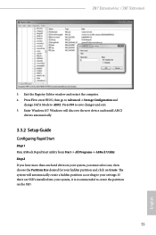
... will discover the new device and install AHCI drivers automatically. 3.3.2 Setup Guide Configuring Rapid Start Step 1 Run ASRock Rapid Start utility from Start -> All Programs -> ASRock Utility. If there are SSD's installed into your settings. Windows will automatically create a hidden partition according to .... 55 English Exit the Registry Editor window and restart the computer. 4. Press F2 to enter BIOS, then go to Advanced ‐> Storage Configuration and change SATA Mode to save changes and exit. 5. Enter Windows 8/7. Press F10 to AHCI. Z87 Extreme6/ac / Z87 Extreme6 3.
... will discover the new device and install AHCI drivers automatically. 3.3.2 Setup Guide Configuring Rapid Start Step 1 Run ASRock Rapid Start utility from Start -> All Programs -> ASRock Utility. If there are SSD's installed into your settings. Windows will automatically create a hidden partition according to .... 55 English Exit the Registry Editor window and restart the computer. 4. Press F2 to enter BIOS, then go to Advanced ‐> Storage Configuration and change SATA Mode to save changes and exit. 5. Enter Windows 8/7. Press F10 to AHCI. Z87 Extreme6/ac / Z87 Extreme6 3.


