
User Manual
Page 3
Contents 1 Introduction 7 1.1 Package Contents 7 1.2 Specifications 8 1.3 Motherboard Layout 13 1.4 I/O Panel 15 1.5 WiFi-802.11n Module and ASRock WiFi 2.4GHz Antenna 17 2 Installation 18 2.1 Screw Holes 18 2.2 Pre-installation Precautions 18 2.3 CPU Installation 19 2.4...Modules (DIMM 22 2.6 Expansion Slots (PCI Express Slots 23 2.7 Dual Monitor and Surround Display Features 24 2.8 ASRock Smart Remote Installation Guide 27 2.9 Jumpers Setup 29 2.10 Onboard Headers and Connectors 30 2.11 Serial ATA (SATA) / Serial ATA2 (SATA2) / Serial ATA3 (SATA3) Hard Disks Installation ...
Contents 1 Introduction 7 1.1 Package Contents 7 1.2 Specifications 8 1.3 Motherboard Layout 13 1.4 I/O Panel 15 1.5 WiFi-802.11n Module and ASRock WiFi 2.4GHz Antenna 17 2 Installation 18 2.1 Screw Holes 18 2.2 Pre-installation Precautions 18 2.3 CPU Installation 19 2.4...Modules (DIMM 22 2.6 Expansion Slots (PCI Express Slots 23 2.7 Dual Monitor and Surround Display Features 24 2.8 ASRock Smart Remote Installation Guide 27 2.9 Jumpers Setup 29 2.10 Onboard Headers and Connectors 30 2.11 Serial ATA (SATA) / Serial ATA2 (SATA2) / Serial ATA3 (SATA3) Hard Disks Installation ...
User Manual
Page 8
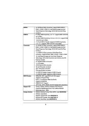
..., AntiVirus Software (Trial Version), CyberLink MediaEspresso 6.5 Trial, ASRock MAGIX Multimedia Suite - Front panel audio connector - 2 x USB 2.0 headers (support 4 USB 2.0 ports) - 1 x USB 3.0 header (supports 2 USB 3.0 ports) - 64Mb AMI UEFI Legal BIOS with GUI support - ASRock Instant Flash (see CAUTION 11) - SATA3 USB3.0 Connector BIOS Feature Support CD Unique Feature - 2 x SATA3 6.0 Gb/s connectors, support RAID (RAID 0, RAID 1, RAID 5, RAID 10...
..., AntiVirus Software (Trial Version), CyberLink MediaEspresso 6.5 Trial, ASRock MAGIX Multimedia Suite - Front panel audio connector - 2 x USB 2.0 headers (support 4 USB 2.0 ports) - 1 x USB 3.0 header (supports 2 USB 3.0 ports) - 64Mb AMI UEFI Legal BIOS with GUI support - ASRock Instant Flash (see CAUTION 11) - SATA3 USB3.0 Connector BIOS Feature Support CD Unique Feature - 2 x SATA3 6.0 Gb/s connectors, support RAID (RAID 0, RAID 1, RAID 5, RAID 10...
User Manual
Page 13
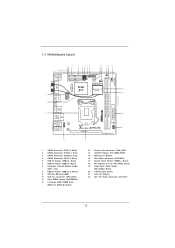
...Z77E-ITX PLED PWRBTN 1 HDLED RESET PANEL1 17 PCIE1 PCI Express 3.0 18 AT X P W R 1 1 SATA2 Connector (SATA_3, Black) 2 SATA3 Connector (SATA3_1, Gray) 3 SATA3 Connector (SATA3_0, Gray) 4 SATA2 Connector (SATA_2, Black) 5 USB 2.0 Header (USB2_3, Black) 6 USB 2.0 Header (USB4_5, Black) 7 Consumer Infrared Module Header (CIR1, Gray) 8 USB 3.0 Header... Fan Connector (CHA_FAN1) 14 mini-PCI Express Slot (MINI_PCIE1) 15 WiFi-802.11n Module 16 ATX Power Connector (ATXPWR1) 17 System Panel Header (PANEL1, Black) 18 PCI Express 3.0 x16 Slot (PCIE1, Black) 19 Front Panel Audio Header (HD_AUDIO1...
...Z77E-ITX PLED PWRBTN 1 HDLED RESET PANEL1 17 PCIE1 PCI Express 3.0 18 AT X P W R 1 1 SATA2 Connector (SATA_3, Black) 2 SATA3 Connector (SATA3_1, Gray) 3 SATA3 Connector (SATA3_0, Gray) 4 SATA2 Connector (SATA_2, Black) 5 USB 2.0 Header (USB2_3, Black) 6 USB 2.0 Header (USB4_5, Black) 7 Consumer Infrared Module Header (CIR1, Gray) 8 USB 3.0 Header... Fan Connector (CHA_FAN1) 14 mini-PCI Express Slot (MINI_PCIE1) 15 WiFi-802.11n Module 16 ATX Power Connector (ATXPWR1) 17 System Panel Header (PANEL1, Black) 18 PCI Express 3.0 x16 Slot (PCIE1, Black) 19 Front Panel Audio Header (HD_AUDIO1...

User Manual
Page 30
... 6.0 Gb/s data transfer rate. Besides two default USB 2.0 ports on the I/O panel, there are NOT jumpers. 2.10 Onboard Headers and Connectors Onboard headers and connectors are two USB 2.0 headers on this motherboard. Serial ATA2 Connectors (SATA_2: see p.13, No. 4) (SATA_3: see p.13, No. 1) SATA_2 SATA_3 Serial ATA3 Connectors (SATA3_0: see p.13, No. 3) (SATA3_1: see p.13, No. 2) SATA3_0 SATA3_1...
... 6.0 Gb/s data transfer rate. Besides two default USB 2.0 ports on the I/O panel, there are NOT jumpers. 2.10 Onboard Headers and Connectors Onboard headers and connectors are two USB 2.0 headers on this motherboard. Serial ATA2 Connectors (SATA_2: see p.13, No. 4) (SATA_3: see p.13, No. 1) SATA_2 SATA_3 Serial ATA3 Connectors (SATA3_0: see p.13, No. 3) (SATA3_1: see p.13, No. 2) SATA3_0 SATA3_1...

User Manual
Page 32
... computer if the computer freezes and fails to the "FrontMic" Tab in the Realtek Control panel. Chassis Fan Connector (4-pin CHA_FAN1) (see p.13, No. 17) This header accommodates several system front panel functions. The LED is on when the hard drive is operating. The LED is on...7 64-bit / VistaTM / VistaTM 64-bit OS: Go to perform a normal restart. System Panel Header (9-pin PANEL1) (see p.13, No. 13) GND +12V CHA_FAN_SPEED FAN_SPEED_CONTROL Please connect the chassis fan cable to the connector and match the black wire to turn off when the system is off your chassis front...
... computer if the computer freezes and fails to the "FrontMic" Tab in the Realtek Control panel. Chassis Fan Connector (4-pin CHA_FAN1) (see p.13, No. 17) This header accommodates several system front panel functions. The LED is on when the hard drive is operating. The LED is on...7 64-bit / VistaTM / VistaTM 64-bit OS: Go to perform a normal restart. System Panel Header (9-pin PANEL1) (see p.13, No. 13) GND +12V CHA_FAN_SPEED FAN_SPEED_CONTROL Please connect the chassis fan cable to the connector and match the black wire to turn off when the system is off your chassis front...

Quick Installation Guide
Page 2
... Chassis Fan Connector (CHA_FAN1) 14 mini-PCI Express Slot (MINI_PCIE1) 15 WiFi-802.11n Module 16 ATX Power Connector (ATXPWR1) 17 System Panel Header (PANEL1, Black) 18 PCI Express 3.0 x16 Slot (PCIE1, Black) 19 Front Panel Audio Header (HD_AUDIO1, Black) 20 1155-Pin CPU Socket 21 Intel Z77 Chipset 22 ATX 12V Power Connector (ATX12V1) English 2 ASRock Z77E-ITX Motherboard
... Chassis Fan Connector (CHA_FAN1) 14 mini-PCI Express Slot (MINI_PCIE1) 15 WiFi-802.11n Module 16 ATX Power Connector (ATXPWR1) 17 System Panel Header (PANEL1, Black) 18 PCI Express 3.0 x16 Slot (PCIE1, Black) 19 Front Panel Audio Header (HD_AUDIO1, Black) 20 1155-Pin CPU Socket 21 Intel Z77 Chipset 22 ATX 12V Power Connector (ATX12V1) English 2 ASRock Z77E-ITX Motherboard
Quick Installation Guide
Page 10
... - ASRock Instant Boot - CPU/Chassis FAN connector - 24 pin ATX power connector - 8 pin 12V power connector - Front panel audio connector - 2 x USB 2.0 headers (support 4 USB 2.0 ports) - 1 x USB 3.0 header (supports 2 USB 3.0 ports) - 64Mb AMI UEFI Legal BIOS with GUI support - Supports jumperfree - ASRock SmartView (see CAUTION 9) - OEM - Supports "Plug and Play" - ASRock Extreme Tuning Utility (AXTU) (see CAUTION 12) English 10 ASRock Z77E-ITX Motherboard...
... - ASRock Instant Boot - CPU/Chassis FAN connector - 24 pin ATX power connector - 8 pin 12V power connector - Front panel audio connector - 2 x USB 2.0 headers (support 4 USB 2.0 ports) - 1 x USB 3.0 header (supports 2 USB 3.0 ports) - 64Mb AMI UEFI Legal BIOS with GUI support - Supports jumperfree - ASRock SmartView (see CAUTION 9) - OEM - Supports "Plug and Play" - ASRock Extreme Tuning Utility (AXTU) (see CAUTION 12) English 10 ASRock Z77E-ITX Motherboard...

Quick Installation Guide
Page 27
...panel, there are NOT jumpers. The current SATA2 interface allows up to 3.0 Gb/s data transfer rate. Serial ATA2 Connectors (SATA_2: see p.2, No. 4) (SATA_3: see p.2, No. 1) SATA_2 SATA_3 Serial ATA3 Connectors (SATA3_0: see p.2, No. 3) (SATA3_1: see p.2, No. 2) SATA3_0 SATA3_1 mSATA Connector... (see p.2, No. 5) Either end of the motherboard! This mSATA connector can support two USB 2.0 ports. 27 ASRock Z77E-ITX Motherboard Do NOT place jumper caps over the headers and connectors ...
...panel, there are NOT jumpers. The current SATA2 interface allows up to 3.0 Gb/s data transfer rate. Serial ATA2 Connectors (SATA_2: see p.2, No. 4) (SATA_3: see p.2, No. 1) SATA_2 SATA_3 Serial ATA3 Connectors (SATA3_0: see p.2, No. 3) (SATA3_1: see p.2, No. 2) SATA3_0 SATA3_1 mSATA Connector... (see p.2, No. 5) Either end of the motherboard! This mSATA connector can support two USB 2.0 ports. 27 ASRock Z77E-ITX Motherboard Do NOT place jumper caps over the headers and connectors ...

Quick Installation Guide
Page 29
... ASRock Z77E-ITX Motherboard Adjust "Recording Volume". The LED is off (S5). The front panel design may configure the way to the reset switch on the chassis front panel. Connect the power switch, reset switch and system status indicator on the chassis to this header... VistaTM / VistaTM 64-bit OS: Go to the power switch on the chassis front panel. System Panel Header (9-pin PANEL1) (see p.2, No. 13) GND +12V CHA_FAN_SPEED FAN_SPEED_CONTROL Please connect the chassis fan cable to the connector and match the black wire to perform a normal restart. PWRBTN (Power Switch): Connect...
... ASRock Z77E-ITX Motherboard Adjust "Recording Volume". The LED is off (S5). The front panel design may configure the way to the reset switch on the chassis front panel. Connect the power switch, reset switch and system status indicator on the chassis to this header... VistaTM / VistaTM 64-bit OS: Go to the power switch on the chassis front panel. System Panel Header (9-pin PANEL1) (see p.2, No. 13) GND +12V CHA_FAN_SPEED FAN_SPEED_CONTROL Please connect the chassis fan cable to the connector and match the black wire to perform a normal restart. PWRBTN (Power Switch): Connect...


