User Manual
Page 5
... set the BIOS option in , 30.5 cm x 24.4 cm) ASRock Z77 Extreme9 Quick Installation Guide ASRock Z77 Extreme9 Support CD 6 x Serial ATA (SATA) Data Cables (Optional) 2 x Serial ATA (SATA) HDD Power Cables (Optional) 1 x I/O Panel Shield 2 x ASRock SLI_Bridge Cards 1 x ASRock SLI_Bridge_3S Card 1 x ASRock 3-Way SLI Bridge Card 1 x ASRock Wi-SB Box 12 x Screws ASRock Reminds You... You may find the latest VGA...
... set the BIOS option in , 30.5 cm x 24.4 cm) ASRock Z77 Extreme9 Quick Installation Guide ASRock Z77 Extreme9 Support CD 6 x Serial ATA (SATA) Data Cables (Optional) 2 x Serial ATA (SATA) HDD Power Cables (Optional) 1 x I/O Panel Shield 2 x ASRock SLI_Bridge Cards 1 x ASRock SLI_Bridge_3S Card 1 x ASRock 3-Way SLI Bridge Card 1 x ASRock Wi-SB Box 12 x Screws ASRock Reminds You... You may find the latest VGA...
User Manual
Page 8
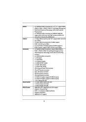
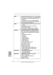
... USB3.0 Connector Smart Switch BIOS Feature - 2 x SATA3 6.0 Gb/s connectors by Intel® Z77, support RAID (RAID 0, RAID 1, RAID 5, RAID 10, Intel Rapid Storage and Intel Smart ...Switch with LED - 1 x Reset Switch with LED - 64Mb AMI UEFI Legal BIOS with eSATA3 port) - 4 x Rear USB 3.0 ports by Intel® Z77, support USB 1.0/2.0/3.0 up to 5Gb/s - 4 x Rear USB 3.0 ports by Etron EJ188, support USB 1.0/2.0/3.0 up to 5Gb/s - 2 x Front USB ...- CPU/Chassis/Power FAN connector - 24 pin ATX power connector - 8 pin 12V power connector - SLI/XFire power connector - Supports jumperfree -
... USB3.0 Connector Smart Switch BIOS Feature - 2 x SATA3 6.0 Gb/s connectors by Intel® Z77, support RAID (RAID 0, RAID 1, RAID 5, RAID 10, Intel Rapid Storage and Intel Smart ...Switch with LED - 1 x Reset Switch with LED - 64Mb AMI UEFI Legal BIOS with eSATA3 port) - 4 x Rear USB 3.0 ports by Intel® Z77, support USB 1.0/2.0/3.0 up to 5Gb/s - 4 x Rear USB 3.0 ports by Etron EJ188, support USB 1.0/2.0/3.0 up to 5Gb/s - 2 x Front USB ...- CPU/Chassis/Power FAN connector - 24 pin ATX power connector - 8 pin 12V power connector - SLI/XFire power connector - Supports jumperfree -
User Manual
Page 14
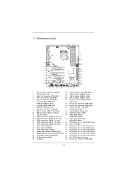
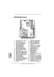
...+ Top: Central/Bass LINE IN Center: REAR SPK FRONT Top: Center: 4-Way SLI SATA2_4_5 SATA2_2_3 SATA3_0_1 SATA3_A3_A4 SATA3_A1_A2 ErP/EuP Ready PCI Express 3.0 CHA_FAN3 SLI/XFIRE_PWR1 PCIE1 X X Fast USB Fast LAN PCIE2 LAN PHY PCIE3 USB3_11_12 USB3_9_10 Super I/O PCIE4 Z77 Extreme9 XFast RAM PCIE5 MINI_PCIE1 PCIE6 WiFi+BT Module CMOS Battery AUDIO CODEC RoHS...
...+ Top: Central/Bass LINE IN Center: REAR SPK FRONT Top: Center: 4-Way SLI SATA2_4_5 SATA2_2_3 SATA3_0_1 SATA3_A3_A4 SATA3_A1_A2 ErP/EuP Ready PCI Express 3.0 CHA_FAN3 SLI/XFIRE_PWR1 PCIE1 X X Fast USB Fast LAN PCIE2 LAN PHY PCIE3 USB3_11_12 USB3_9_10 Super I/O PCIE4 Z77 Extreme9 XFast RAM PCIE5 MINI_PCIE1 PCIE6 WiFi+BT Module CMOS Battery AUDIO CODEC RoHS...

User Manual
Page 28
... Card to the goldfingers on the slots. Two Goldfingers 28 Make sure the ASRock SLI_Bridge_3S Card is inserted to the monitor connector or the DVI connector of graphics cards will not work together properly. (Even the GPU chips version ...shall be the same.) Each graphics card should have two goldfingers for the 3-Way SLI Bridge connector. Insert one graphics card into PCIE1 slot, another graphics card to PCIE3 slot, and the other graphics card to the PCI Express graphics...
... Card to the goldfingers on the slots. Two Goldfingers 28 Make sure the ASRock SLI_Bridge_3S Card is inserted to the monitor connector or the DVI connector of graphics cards will not work together properly. (Even the GPU chips version ...shall be the same.) Each graphics card should have two goldfingers for the 3-Way SLI Bridge connector. Insert one graphics card into PCIE1 slot, another graphics card to PCIE3 slot, and the other graphics card to the PCI Express graphics...

User Manual
Page 29
Step2. Please make sure that is firmly in place. Make sure the ASRock 3-Way SLI Bridge Card is inserted to the monitor connector or the DVI connector of the graphics card that both power connectors on the three graphics cards. ASRock 3-Way SLI Bridge Card Step4. Repeat this step on the PCI Express graphics card are connected. Connect the auxiliary power source to the goldfingers on each graphics card. Step3. Align and insert the ASRock 3-Way SLI Bridge Card to the PCI Express graphics card. Connect a VGA cable or a DVI cable to PCIE1 slot. 29
Step2. Please make sure that is firmly in place. Make sure the ASRock 3-Way SLI Bridge Card is inserted to the monitor connector or the DVI connector of the graphics card that both power connectors on the three graphics cards. ASRock 3-Way SLI Bridge Card Step4. Repeat this step on the PCI Express graphics card are connected. Connect the auxiliary power source to the goldfingers on each graphics card. Step3. Align and insert the ASRock 3-Way SLI Bridge Card to the PCI Express graphics card. Connect a VGA cable or a DVI cable to PCIE1 slot. 29

User Manual
Page 30
... of the first and second graphics card. Connect the second and the fourth graphics card with the ASRock SLI_Bridge_3S Card. Align and insert an ASRock SLI Bridge Card to PCIE1 slot. 30 Make sure the ASRock SLI Bridge Cards are properly seated on the slots. Step3. Please make sure that both power connectors on... will not work together properly. (Even the GPU chips version shall be the same.) Each graphics card should have two goldfingers for the ASRock SLI Bridge Card connectors. Connect a VGA cable or a DVI cable to the PCI Express graphics card.
... of the first and second graphics card. Connect the second and the fourth graphics card with the ASRock SLI_Bridge_3S Card. Align and insert an ASRock SLI Bridge Card to PCIE1 slot. 30 Make sure the ASRock SLI Bridge Cards are properly seated on the slots. Step3. Please make sure that both power connectors on... will not work together properly. (Even the GPU chips version shall be the same.) Each graphics card should have two goldfingers for the ASRock SLI Bridge Card connectors. Connect a VGA cable or a DVI cable to the PCI Express graphics card.
User Manual
Page 31
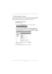
... the graphics card drivers to enable the multi-GPU feature. B. Please follow the below procedures to your system. From the pop-up menu, select Set SLI and PhysX configuration. In Set PhysX GPU acceleration item, please select Enabled. And click Apply. You can enable the MultiGraphics Processing Unit (GPU... can freely enjoy the benefit of SLITM feature. 31 For Windows® XP / XP 64-bit OS: (For SLITM mode only) A. In Select an SLI configuration item, please select Enable...
... the graphics card drivers to enable the multi-GPU feature. B. Please follow the below procedures to your system. From the pop-up menu, select Set SLI and PhysX configuration. In Set PhysX GPU acceleration item, please select Enabled. And click Apply. You can enable the MultiGraphics Processing Unit (GPU... can freely enjoy the benefit of SLITM feature. 31 For Windows® XP / XP 64-bit OS: (For SLITM mode only) A. In Select an SLI configuration item, please select Enable...

User Manual
Page 32
From the pop-up menu, select Set SLI and PhysX configuration. F. G. For Windows® VistaTM / VistaTM 64-bit / 7 / 7 64-bit OS: (For SLITM and Quad SLITM mode) A. Click the Start icon ... Panel tab. Select Control Panel tab. From the pop-up menu, select All Programs, and then click NVIDIA Corporation. In Select an SLI configuration item, please select Enable SLI. D. C. E. Reboot your Windows taskbar. You can freely enjoy the benefit of SLITM or Quad SLITM feature. 32 B. In Set PhysX...
From the pop-up menu, select Set SLI and PhysX configuration. F. G. For Windows® VistaTM / VistaTM 64-bit / 7 / 7 64-bit OS: (For SLITM and Quad SLITM mode) A. Click the Start icon ... Panel tab. Select Control Panel tab. From the pop-up menu, select All Programs, and then click NVIDIA Corporation. In Select an SLI configuration item, please select Enable SLI. D. C. E. Reboot your Windows taskbar. You can freely enjoy the benefit of SLITM or Quad SLITM feature. 32 B. In Set PhysX...

User Manual
Page 33
C. From the pop-up menu, select Set SLI and PhysX configuration. You can freely enjoy the benefits of 3-Way SLITM or 4-Way SLITM. * SLITM appearing here is a registered trademark ... identification or explanation and to the owners' benefit, without intent to D on page 32. D. In Select an SLI configuration item, please select Enable 3-way SLI or Enable 4-way SLI. For Windows® VistaTM / VistaTM 64-bit / 7 / 7 64-bit OS: (For 3-Way SLITM or 4-Way SLITM mode) A. And click...
C. From the pop-up menu, select Set SLI and PhysX configuration. You can freely enjoy the benefits of 3-Way SLITM or 4-Way SLITM. * SLITM appearing here is a registered trademark ... identification or explanation and to the owners' benefit, without intent to D on page 32. D. In Select an SLI configuration item, please select Enable 3-way SLI or Enable 4-way SLI. For Windows® VistaTM / VistaTM 64-bit / 7 / 7 64-bit OS: (For 3-Way SLITM or 4-Way SLITM mode) A. And click...

User Manual
Page 53
... this connector, but please connect it with a hard disk power connecor when two graphics cards are plugged to this header. 53 SLI/XFIRE Power Connector (4-pin SLI/XFIRE_PWR1) (see p.14 No. 45) SLI/XFIRE_POWER1 It is one IEEE 1394 port. IEEE 1394 Header (9-pin FRONT_1394) (see p.14 No. 32) RXTPAM_0 GND RXTPBM_0 +12V...
... this connector, but please connect it with a hard disk power connecor when two graphics cards are plugged to this header. 53 SLI/XFIRE Power Connector (4-pin SLI/XFIRE_PWR1) (see p.14 No. 45) SLI/XFIRE_POWER1 It is one IEEE 1394 port. IEEE 1394 Header (9-pin FRONT_1394) (see p.14 No. 32) RXTPAM_0 GND RXTPBM_0 +12V...
Quick Installation Guide
Page 2
... LINE IN Center: REAR SPK FRONT Top: Center: 4-Way SLI SATA2_4_5 SATA2_2_3 SATA3_0_1 SATA3_A3_A4 SATA3_A1_A2 ErP/EuP Ready PCI Express 3.0 CHA_FAN3 SLI/XFIRE_PWR1 PCIE1 X X Fast USB Fast LAN PCIE2 LAN PHY PCIE3 USB3_11_12 USB3_9_10 Super I/O PCIE4 Z77 Extreme9 XFast RAM PCIE5 MINI_PCIE1 PCIE6 WiFi+BT Module CMOS Battery AUDIO ...x16 Slot (PCIE2, Black) 22 Clear CMOS Jumper (CLRCMOS1) 44 PCI Express 3.0 x16 Slot (PCIE1, Black) 23 SPI Flash Memory (64Mb) 45 SLI / XFIRE Power Connector 24 Dr. Debug 46 Chassis Fan Connector (CHA_FAN3) English 2 ASRock Z77 Extreme9 Motherboard
... LINE IN Center: REAR SPK FRONT Top: Center: 4-Way SLI SATA2_4_5 SATA2_2_3 SATA3_0_1 SATA3_A3_A4 SATA3_A1_A2 ErP/EuP Ready PCI Express 3.0 CHA_FAN3 SLI/XFIRE_PWR1 PCIE1 X X Fast USB Fast LAN PCIE2 LAN PHY PCIE3 USB3_11_12 USB3_9_10 Super I/O PCIE4 Z77 Extreme9 XFast RAM PCIE5 MINI_PCIE1 PCIE6 WiFi+BT Module CMOS Battery AUDIO ...x16 Slot (PCIE2, Black) 22 Clear CMOS Jumper (CLRCMOS1) 44 PCI Express 3.0 x16 Slot (PCIE1, Black) 23 SPI Flash Memory (64Mb) 45 SLI / XFIRE Power Connector 24 Dr. Debug 46 Chassis Fan Connector (CHA_FAN3) English 2 ASRock Z77 Extreme9 Motherboard
Quick Installation Guide
Page 7
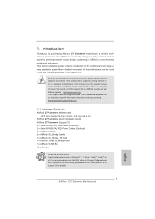
...Configuration to the "User Manual" in our support CD for details. 7 ASRock Z77 Extreme9 Motherboard English In case any modifications of this manual will be subject to ...ASRock Z77 Extreme9 Quick Installation Guide ASRock Z77 Extreme9 Support CD 6 x Serial ATA (SATA) Data Cables (Optional) 2 x Serial ATA (SATA) HDD Power Cables (Optional) 1 x I/O Panel Shield 2 x ASRock SLI_Bridge Cards 1 x ASRock SLI_Bridge_3S Card 1 x ASRock 3-Way SLI Bridge Card 1 x ASRock Wi-SB Box 12 x Screws ASRock Reminds You... www.asrock.com/support/index.asp 1.1 Package Contents ASRock Z77 Extreme9...
...Configuration to the "User Manual" in our support CD for details. 7 ASRock Z77 Extreme9 Motherboard English In case any modifications of this manual will be subject to ...ASRock Z77 Extreme9 Quick Installation Guide ASRock Z77 Extreme9 Support CD 6 x Serial ATA (SATA) Data Cables (Optional) 2 x Serial ATA (SATA) HDD Power Cables (Optional) 1 x I/O Panel Shield 2 x ASRock SLI_Bridge Cards 1 x ASRock SLI_Bridge_3S Card 1 x ASRock 3-Way SLI Bridge Card 1 x ASRock Wi-SB Box 12 x Screws ASRock Reminds You... www.asrock.com/support/index.asp 1.1 Package Contents ASRock Z77 Extreme9...
Quick Installation Guide
Page 10
... 12V power connector - SMBIOS 2.3.1 Support English 10 ASRock Z77 Extreme9 Motherboard ACPI 1.1 Compliance Wake Up Events - SLI/XFire power connector - Supports jumperfree - SATA3 USB3.0 Connector Smart Switch BIOS Feature - 2 x SATA3 6.0 Gb/s connectors by Intel® Z77, support RAID (RAID 0, RAID 1, RAID 5, RAID...Switch with LED - 1 x Reset Switch with LED - 64Mb AMI UEFI Legal BIOS with eSATA3 port) - 4 x Rear USB 3.0 ports by Intel® Z77, support USB 1.0/2.0/3.0 up to 5Gb/s - 4 x Rear USB 3.0 ports by Etron EJ188, support USB 1.0/2.0/3.0 up to 5Gb/s - 2 x Front USB 3.0 ...
... 12V power connector - SMBIOS 2.3.1 Support English 10 ASRock Z77 Extreme9 Motherboard ACPI 1.1 Compliance Wake Up Events - SLI/XFire power connector - Supports jumperfree - SATA3 USB3.0 Connector Smart Switch BIOS Feature - 2 x SATA3 6.0 Gb/s connectors by Intel® Z77, support RAID (RAID 0, RAID 1, RAID 5, RAID...Switch with LED - 1 x Reset Switch with LED - 64Mb AMI UEFI Legal BIOS with eSATA3 port) - 4 x Rear USB 3.0 ports by Intel® Z77, support USB 1.0/2.0/3.0 up to 5Gb/s - 4 x Rear USB 3.0 ports by Etron EJ188, support USB 1.0/2.0/3.0 up to 5Gb/s - 2 x Front USB 3.0 ...

Quick Installation Guide
Page 25
Two Goldfingers 25 ASRock Z77 Extreme9 Motherboard English Step2. Make sure the ASRock SLI_Bridge_3S Card is inserted to PCIE1 slot. 2.7.1.2 Installing Three SLITM-Ready Graphics Cards Step 1. Insert one... source to PCIE5 slot. Step3. Connect a VGA cable or a DVI cable to the goldfingers on the slots. ASRock SLI_Bridge_3S Card Step4. Install identical 3-Way SLITM-ready graphics cards that are properly seated on each graphics card. Make sure that is...shall be the same.) Each graphics card should have two goldfingers for the 3-Way SLI Bridge connector.
Two Goldfingers 25 ASRock Z77 Extreme9 Motherboard English Step2. Make sure the ASRock SLI_Bridge_3S Card is inserted to PCIE1 slot. 2.7.1.2 Installing Three SLITM-Ready Graphics Cards Step 1. Insert one... source to PCIE5 slot. Step3. Connect a VGA cable or a DVI cable to the goldfingers on the slots. ASRock SLI_Bridge_3S Card Step4. Install identical 3-Way SLITM-ready graphics cards that are properly seated on each graphics card. Make sure that is...shall be the same.) Each graphics card should have two goldfingers for the 3-Way SLI Bridge connector.

Quick Installation Guide
Page 26
Step3. Repeat this step on the PCI Express graphics card are connected. Align and insert the ASRock 3-Way SLI Bridge Card to the PCI Express graphics card. English 26 ASRock Z77 Extreme9 Motherboard Make sure the ASRock 3-Way SLI Bridge Card is inserted to the monitor connector or the DVI connector of the graphics card that both power... to the goldfingers on each graphics card. Connect a VGA cable or a DVI cable to PCIE1 slot. Please make sure that is firmly in place. ASRock 3-Way SLI Bridge Card Step4. Step2.
Step3. Repeat this step on the PCI Express graphics card are connected. Align and insert the ASRock 3-Way SLI Bridge Card to the PCI Express graphics card. English 26 ASRock Z77 Extreme9 Motherboard Make sure the ASRock 3-Way SLI Bridge Card is inserted to the monitor connector or the DVI connector of the graphics card that both power... to the goldfingers on each graphics card. Connect a VGA cable or a DVI cable to PCIE1 slot. Please make sure that is firmly in place. ASRock 3-Way SLI Bridge Card Step4. Step2.

Quick Installation Guide
Page 27
Make sure that is inserted to PCIE1 slot. 27 ASRock Z77 Extreme9 Motherboard Install the second ASRock SLI Bridge Card to the goldfingers of the third and fourth graphics card. Two Goldfingers Step2. Insert one graphics card into the ... card into the PCIE5 slot and the last graphics card into the PCIE7 slot. Make sure the ASRock SLI Bridge Cards are connected. English 2 ASRock SLI_Bridge Cards and an ASRock SLI_Bridge_3S Card Step4. Align and insert an ASRock SLI Bridge Card to the goldfingers of the first and second graphics card. Connect a VGA...
Make sure that is inserted to PCIE1 slot. 27 ASRock Z77 Extreme9 Motherboard Install the second ASRock SLI Bridge Card to the goldfingers of the third and fourth graphics card. Two Goldfingers Step2. Insert one graphics card into the ... card into the PCIE5 slot and the last graphics card into the PCIE7 slot. Make sure the ASRock SLI Bridge Cards are connected. English 2 ASRock SLI_Bridge Cards and an ASRock SLI_Bridge_3S Card Step4. Align and insert an ASRock SLI Bridge Card to the goldfingers of the first and second graphics card. Connect a VGA...

Quick Installation Guide
Page 28
After that, you can freely enjoy the benefit of SLITM feature. 28 ASRock Z77 Extreme9 Motherboard English B. And click Apply. C. Double-click NVIDIA Settings icon on your system. D. In Set PhysX GPU acceleration item, please select Enabled. You can enable ... below procedures to your Windows® taskbar. For Windows® XP / XP 64-bit OS: (For SLITM mode only) A. Reboot your system. In Select an SLI configuration item, please select Enable SLI. From the pop-up menu, select Set...
After that, you can freely enjoy the benefit of SLITM feature. 28 ASRock Z77 Extreme9 Motherboard English B. And click Apply. C. Double-click NVIDIA Settings icon on your system. D. In Set PhysX GPU acceleration item, please select Enabled. You can enable ... below procedures to your Windows® taskbar. For Windows® XP / XP 64-bit OS: (For SLITM mode only) A. Reboot your system. In Select an SLI configuration item, please select Enable SLI. From the pop-up menu, select Set...

Quick Installation Guide
Page 29
... can freely enjoy the benefit of SLITM or Quad SLITM feature. 29 ASRock Z77 Extreme9 Motherboard English For Windows® VistaTM / VistaTM 64-bit / 7 / 7 64-bit OS: (For SLITM and Quad SLITM mode) A. From the pop-up menu, select Set SLI and PhysX configuration. Select NVIDIA Control Panel tab. G. C. From the... NVIDIA Corporation. In Set PhysX GPU acceleration item, please select Enabled. Reboot your Windows taskbar. Click the Start icon on your system. In Select an SLI configuration item, please select Enable...
... can freely enjoy the benefit of SLITM or Quad SLITM feature. 29 ASRock Z77 Extreme9 Motherboard English For Windows® VistaTM / VistaTM 64-bit / 7 / 7 64-bit OS: (For SLITM and Quad SLITM mode) A. From the pop-up menu, select Set SLI and PhysX configuration. Select NVIDIA Control Panel tab. G. C. From the... NVIDIA Corporation. In Set PhysX GPU acceleration item, please select Enabled. Reboot your Windows taskbar. Click the Start icon on your system. In Select an SLI configuration item, please select Enable...

Quick Installation Guide
Page 30
... 3-Way SLITM or 4-Way SLITM mode) A. In Select an SLI configuration item, please select Enable 3-way SLI or Enable 4-way SLI. From the pop-up menu, select Set SLI and PhysX configuration. Reboot your system. Follow step A to infringe. 30 ASRock Z77 Extreme9 Motherboard English You can freely enjoy the benefits...
... 3-Way SLITM or 4-Way SLITM mode) A. In Select an SLI configuration item, please select Enable 3-way SLI or Enable 4-way SLI. From the pop-up menu, select Set SLI and PhysX configuration. Reboot your system. Follow step A to infringe. 30 ASRock Z77 Extreme9 Motherboard English You can freely enjoy the benefits...

Quick Installation Guide
Page 50
... Connector (4-pin SLI/XFIRE_PWR1) (see p.2 No. 45) SLI/XFIRE_POWER1 It is one IEEE 1394 header (FRONT_1394) on the I/O panel, there is not necessary to use this connector, but please connect it with a hard ... power connecor when two graphics cards are plugged to this motherboard. Please connect the HDMI_SPDIF connector of HDMI VGA card to this header. English 50 ASRock Z77 Extreme9 Motherboard Serial port Header (9-pin COM1) (see p.2, No. 35) 1 GND SPDIFOUT HDMI_SPDIF header, providing SPDIF audio output to HDMI VGA card, allows the system to...
... Connector (4-pin SLI/XFIRE_PWR1) (see p.2 No. 45) SLI/XFIRE_POWER1 It is one IEEE 1394 header (FRONT_1394) on the I/O panel, there is not necessary to use this connector, but please connect it with a hard ... power connecor when two graphics cards are plugged to this motherboard. Please connect the HDMI_SPDIF connector of HDMI VGA card to this header. English 50 ASRock Z77 Extreme9 Motherboard Serial port Header (9-pin COM1) (see p.2, No. 35) 1 GND SPDIFOUT HDMI_SPDIF header, providing SPDIF audio output to HDMI VGA card, allows the system to...