
User Manual
Page 5
... the latest VGA cards and CPU support lists on ASRock website without notice. Chapter 1: Introduction Thank you are using. ASRock website http://www.asrock.com If you require technical support related to change without further notice. www.asrock.com/support/index.asp 1.1 Package Contents ASRock Z77 Extreme3 Motherboard (ATX Form Factor: 12.0-in x 8.6-in Storage Configuration to AHCI...
... the latest VGA cards and CPU support lists on ASRock website without notice. Chapter 1: Introduction Thank you are using. ASRock website http://www.asrock.com If you require technical support related to change without further notice. www.asrock.com/support/index.asp 1.1 Package Contents ASRock Z77 Extreme3 Motherboard (ATX Form Factor: 12.0-in x 8.6-in Storage Configuration to AHCI...

User Manual
Page 6
...VGA outputs can be supported only with Intel® Ivy Bridge CPU. Max. Intel® Z77 - Max. Supports NVIDIA® Quad SLITM and SLITM * Intel® HD Graphics Built...-ECC, un-buffered memory - Supports Intel® Rapid Start Technology and Smart Connect Technology - ASRock DuraCap (2.5 x longer life time) (100% Japan-made high-quality Conductive Polymer Capacitors) - ... with Intel® Sandy Bridge CPU. - Supports Intel® Turbo Boost 2.0 Technology - shared memory 1760MB 6 ATX Form Factor: 12.0-in x 8.6-in LGA1155 Package - Supports 3rd and 2nd Generation Intel® CoreTM i7 / ...
...VGA outputs can be supported only with Intel® Ivy Bridge CPU. Max. Intel® Z77 - Max. Supports NVIDIA® Quad SLITM and SLITM * Intel® HD Graphics Built...-ECC, un-buffered memory - Supports Intel® Rapid Start Technology and Smart Connect Technology - ASRock DuraCap (2.5 x longer life time) (100% Japan-made high-quality Conductive Polymer Capacitors) - ... with Intel® Sandy Bridge CPU. - Supports Intel® Turbo Boost 2.0 Technology - shared memory 1760MB 6 ATX Form Factor: 12.0-in x 8.6-in LGA1155 Package - Supports 3rd and 2nd Generation Intel® CoreTM i7 / ...

User Manual
Page 8
...64-bit / VistaTM / VistaTM 64-bit / XP / XP 64-bit compliant (see CAUTION 4) 8 Supports jumperfree - Drivers, Utilities, AntiVirus Software (Trial Version), CyberLink MediaEspresso 6.5 Trial, ASRock MAGIX Multimedia Suite - Front panel audio connector - 2 x USB 2.0 headers (support 4 USB 2.0 ports) - 1 x USB 3.0 header (supports 2 USB 3.0 ports) - 64Mb AMI ... header - 1 x Power LED header - 2 x CPU Fan connectors (1 x 4-pin, 1 x 3-pin) - 3 x Chassis Fan connectors (1 x 4-pin, 2 x 3-pin) - 1 x Power Fan connector (3-pin) - 24 pin ATX power connector - 8 pin 12V power connector -
...64-bit / VistaTM / VistaTM 64-bit / XP / XP 64-bit compliant (see CAUTION 4) 8 Supports jumperfree - Drivers, Utilities, AntiVirus Software (Trial Version), CyberLink MediaEspresso 6.5 Trial, ASRock MAGIX Multimedia Suite - Front panel audio connector - 2 x USB 2.0 headers (support 4 USB 2.0 ports) - 1 x USB 3.0 header (supports 2 USB 3.0 ports) - 64Mb AMI ... header - 1 x Power LED header - 2 x CPU Fan connectors (1 x 4-pin, 1 x 3-pin) - 3 x Chassis Fan connectors (1 x 4-pin, 2 x 3-pin) - 1 x Power Fan connector (3-pin) - 24 pin ATX power connector - 8 pin 12V power connector -
User Manual
Page 15
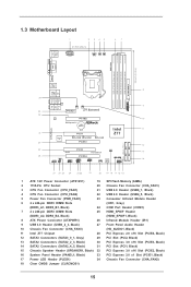
... LAN PHY 9 Top: LINE IN Center: Bottom: MIC IN CHA_FAN2 CHA_FAN3 33 PCIE1 Z77 Extreme3 32 AUDIO CODEC PCIE2 10 PCI Express 3.0 CMOS Battery Intel 11 ErP/EuP Ready 31 PCI1 Z77 Super I/O X X X Fast USB Fast RAM Fast LAN 30 PCIE3 12 SATA2_4_5 SATA2_2_3...DDR3_B1, Black) 24 COM Port Header (COM1) 7 2 x 240-pin DDR3 DIMM Slots 25 HDMI_SPDIF Header (DDR3_A2, DDR3_B2, Black) (HDMI_SPDIF1, Black) 8 ATX Power Connector (ATXPWR1) 26 Infrared Module Header (IR1) 9 USB 3.0 Header (USB3_2_3, Black) 27 Front Panel Audio Header 10 Chassis Fan Connector (CHA_FAN3) (HD_AUDIO1...
... LAN PHY 9 Top: LINE IN Center: Bottom: MIC IN CHA_FAN2 CHA_FAN3 33 PCIE1 Z77 Extreme3 32 AUDIO CODEC PCIE2 10 PCI Express 3.0 CMOS Battery Intel 11 ErP/EuP Ready 31 PCI1 Z77 Super I/O X X X Fast USB Fast RAM Fast LAN 30 PCIE3 12 SATA2_4_5 SATA2_2_3...DDR3_B1, Black) 24 COM Port Header (COM1) 7 2 x 240-pin DDR3 DIMM Slots 25 HDMI_SPDIF Header (DDR3_A2, DDR3_B2, Black) (HDMI_SPDIF1, Black) 8 ATX Power Connector (ATXPWR1) 26 Infrared Module Header (IR1) 9 USB 3.0 Header (USB3_2_3, Black) 27 Front Panel Audio Header 10 Chassis Fan Connector (CHA_FAN3) (HD_AUDIO1...
User Manual
Page 18
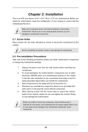
... to do not over -tighten the screws! static pad or in the bag that the power is switched off or the power cord is an ATX form factor (12.0" x 8.6", 30.5 x 21.8 cm) motherboard. Chapter 2: Installation This is detached from the wall socket before touching any components. 2. Failure to do so may...
... to do not over -tighten the screws! static pad or in the bag that the power is switched off or the power cord is an ATX form factor (12.0" x 8.6", 30.5 x 21.8 cm) motherboard. Chapter 2: Installation This is detached from the wall socket before touching any components. 2. Failure to do so may...

User Manual
Page 38
Please make sure the wire assignments and the USB_PWR PP+ GND DUMMY pin assignments are matched correctly. 1 23 45 GND IRTX IRRX ATX+5VSB Step3. Boot up your system and install Multi-Angle CIR Receiver to below , pin 1-5) and the CIR header. Make sure the option "CIR ... option, please shut down your system. Step5. Find the CIR header located next to enter BIOS Setup Utility. Execute ASRock support CD and install CIR Driver. (It is setting at the bottom of ASRock Smart Remote. USB 2.0 header (9-pin, black) CIR header (4-pin, gray) Step2. Press or to the USB 2.0 ...
Please make sure the wire assignments and the USB_PWR PP+ GND DUMMY pin assignments are matched correctly. 1 23 45 GND IRTX IRRX ATX+5VSB Step3. Boot up your system and install Multi-Angle CIR Receiver to below , pin 1-5) and the CIR header. Make sure the option "CIR ... option, please shut down your system. Step5. Find the CIR header located next to enter BIOS Setup Utility. Execute ASRock support CD and install CIR Driver. (It is setting at the bottom of ASRock Smart Remote. USB 2.0 header (9-pin, black) CIR header (4-pin, gray) Step2. Press or to the USB 2.0 ...

User Manual
Page 44
... 3-Pin CPU fan to the CPU fan connector on this motherboard, please connect it can work if you adopt a traditional 20-pin ATX power supply. Chassis and Power Fan Connectors (4-pin CHA_FAN1) (see p.15, No. 20) FAN_SPEED_CONTROL GND +12V CHA_FAN_SPEED (3-pin CHA_FAN2)...Pin 1-3 Connected 3-Pin Fan Installation (3-pin CPU_FAN2) (see p.15, No. 4) GND +12V CPU_FAN_SPEED ATX Power Connector (24-pin ATXPWR1) (see p.15, No. 8) 12 24 Please connect an ATX power supply to the ground pin. CPU Fan Connectors FAN_SPEED_CONTROL (4-pin CPU_FAN1) CPU_FAN_SPEED +12V (see p....
... 3-Pin CPU fan to the CPU fan connector on this motherboard, please connect it can work if you adopt a traditional 20-pin ATX power supply. Chassis and Power Fan Connectors (4-pin CHA_FAN1) (see p.15, No. 20) FAN_SPEED_CONTROL GND +12V CHA_FAN_SPEED (3-pin CHA_FAN2)...Pin 1-3 Connected 3-Pin Fan Installation (3-pin CPU_FAN2) (see p.15, No. 4) GND +12V CPU_FAN_SPEED ATX Power Connector (24-pin ATXPWR1) (see p.15, No. 8) 12 24 Please connect an ATX power supply to the ground pin. CPU Fan Connectors FAN_SPEED_CONTROL (4-pin CPU_FAN1) CPU_FAN_SPEED +12V (see p....

User Manual
Page 45
...HDMI_SPDIF Header (2-pin HDMI_SPDIF1) (see p.15, No. 24) This COM1 header supports a serial port module. To use the 4-pin ATX power supply, please plug your power supply along with Pin 1 and Pin 5. 8 5 4-Pin ATX 12V Power Supply Installation 4 1 Serial port Header (9-pin COM1) (see p.15, No. 25 1 GND SPDIFOUT HDMI_SPDIF header, ... this connector. Please connect the HDMI_SPDIF connector of HDMI VGA card to connect HDMI Digital TV/ projector/LCD devices. Though this motherboard provides 8-pin ATX 12V power connector, it can still work if you adopt a traditional 4-pin...
...HDMI_SPDIF Header (2-pin HDMI_SPDIF1) (see p.15, No. 24) This COM1 header supports a serial port module. To use the 4-pin ATX power supply, please plug your power supply along with Pin 1 and Pin 5. 8 5 4-Pin ATX 12V Power Supply Installation 4 1 Serial port Header (9-pin COM1) (see p.15, No. 25 1 GND SPDIFOUT HDMI_SPDIF header, ... this connector. Please connect the HDMI_SPDIF connector of HDMI VGA card to connect HDMI Digital TV/ projector/LCD devices. Though this motherboard provides 8-pin ATX 12V power connector, it can still work if you adopt a traditional 4-pin...

Quick Installation Guide
Page 2
... PLED PWRBTN 1 HDLED RESET 13 14 27 26 25 24 23 22 21 20 19 18 17 16 15 1 ATX 12V Power Connector (ATX12V1) 19 SPI Flash Memory (64Mb) 2 1155-Pin CPU Socket 20 Chassis Fan Connector (CHA_FAN1... COM Port Header (COM1) 7 2 x 240-pin DDR3 DIMM Slots 25 HDMI_SPDIF Header (DDR3_A2, DDR3_B2, Black) (HDMI_SPDIF1, Black) 8 ATX Power Connector (ATXPWR1) 26 Infrared Module Header (IR1) 9 USB 3.0 Header (USB3_2_3, Black) 27 Front Panel Audio Header 10 Chassis Fan...PLED1) 34 Chassis Fan Connector (CHA_FAN2) 18 Clear CMOS Jumper (CLRCMOS1) 2 ASRock Z77 Extreme3 Motherboard English
... PLED PWRBTN 1 HDLED RESET 13 14 27 26 25 24 23 22 21 20 19 18 17 16 15 1 ATX 12V Power Connector (ATX12V1) 19 SPI Flash Memory (64Mb) 2 1155-Pin CPU Socket 20 Chassis Fan Connector (CHA_FAN1... COM Port Header (COM1) 7 2 x 240-pin DDR3 DIMM Slots 25 HDMI_SPDIF Header (DDR3_A2, DDR3_B2, Black) (HDMI_SPDIF1, Black) 8 ATX Power Connector (ATXPWR1) 26 Infrared Module Header (IR1) 9 USB 3.0 Header (USB3_2_3, Black) 27 Front Panel Audio Header 10 Chassis Fan...PLED1) 34 Chassis Fan Connector (CHA_FAN2) 18 Clear CMOS Jumper (CLRCMOS1) 2 ASRock Z77 Extreme3 Motherboard English

Quick Installation Guide
Page 5
... specific information about the model you for details. 5 ASRock Z77 Extreme3 Motherboard English www.asrock.com/support/index.asp 1.1 Package Contents ASRock Z77 Extreme3 Motherboard (ATX Form Factor: 12.0-in x 8.6-in Storage Configuration to set the BIOS option in , 30.5 cm x 21.8 cm) ASRock Z77 Extreme3 Quick Installation Guide ASRock Z77 Extreme3 Support CD 2 x Serial ATA (SATA) Data Cables (Optional) 1 x I/O Panel...
... specific information about the model you for details. 5 ASRock Z77 Extreme3 Motherboard English www.asrock.com/support/index.asp 1.1 Package Contents ASRock Z77 Extreme3 Motherboard (ATX Form Factor: 12.0-in x 8.6-in Storage Configuration to set the BIOS option in , 30.5 cm x 21.8 cm) ASRock Z77 Extreme3 Quick Installation Guide ASRock Z77 Extreme3 Support CD 2 x Serial ATA (SATA) Data Cables (Optional) 1 x I/O Panel...

Quick Installation Guide
Page 6
1.2 Specifications Platform CPU Chipset Memory Expansion Slot Graphics - ATX Form Factor: 12.0-in x 8.6-in Visuals and the VGA outputs can be supported only with Intel® Sandy Bridge CPU. - Supports ..., it only supports PCIE 2.0. - 1 x PCI Express 2.0 x16 slot (PCIE4 @ x4 mode) - 1 x PCI Express 2.0 x 1 slot - 2 x PCI slots - shared memory 1760MB English 6 ASRock Z77 Extreme3 Motherboard Supports AMD Quad CrossFireXTM, 3-Way CrossFireXTM and CrossFireXTM - Digi Power Design - 8 + 3 Power Phase Design - Supports Intel® Rapid Start Technology and Smart Connect Technology...
1.2 Specifications Platform CPU Chipset Memory Expansion Slot Graphics - ATX Form Factor: 12.0-in x 8.6-in Visuals and the VGA outputs can be supported only with Intel® Sandy Bridge CPU. - Supports ..., it only supports PCIE 2.0. - 1 x PCI Express 2.0 x16 slot (PCIE4 @ x4 mode) - 1 x PCI Express 2.0 x 1 slot - 2 x PCI slots - shared memory 1760MB English 6 ASRock Z77 Extreme3 Motherboard Supports AMD Quad CrossFireXTM, 3-Way CrossFireXTM and CrossFireXTM - Digi Power Design - 8 + 3 Power Phase Design - Supports Intel® Rapid Start Technology and Smart Connect Technology...

Quick Installation Guide
Page 8
...connectors (1 x 4-pin, 1 x 3-pin) - 3 x Chassis Fan connectors (1 x 4-pin, 2 x 3-pin) - 1 x Power Fan connector (3-pin) - 24 pin ATX power connector - 8 pin 12V power connector - Supports jumperfree - OEM - CPU/Chassis Quiet Fan (Allows Chassis Fan Speed AutoAdjust by CPU Temperature) - Front panel audio connector... ASRock MAGIX Multimedia Suite - CPU/Chassis/Power Fan Tachometer - Supports "Plug and Play" - Chassis Temperature Sensing - Microsoft® Windows® 7 / 7 64-bit / VistaTM / VistaTM 64-bit / XP / XP 64-bit compliant (see CAUTION 4) ASRock Z77 Extreme3 Motherboard...
...connectors (1 x 4-pin, 1 x 3-pin) - 3 x Chassis Fan connectors (1 x 4-pin, 2 x 3-pin) - 1 x Power Fan connector (3-pin) - 24 pin ATX power connector - 8 pin 12V power connector - Supports jumperfree - OEM - CPU/Chassis Quiet Fan (Allows Chassis Fan Speed AutoAdjust by CPU Temperature) - Front panel audio connector... ASRock MAGIX Multimedia Suite - CPU/Chassis/Power Fan Tachometer - Supports "Plug and Play" - Chassis Temperature Sensing - Microsoft® Windows® 7 / 7 64-bit / VistaTM / VistaTM 64-bit / XP / XP 64-bit compliant (see CAUTION 4) ASRock Z77 Extreme3 Motherboard...

Quick Installation Guide
Page 15
... or removing the motherboard. Make sure to static electricity, NEVER place your chassis to the motherboard, peripherals, and/or components. 15 ASRock Z77 Extreme3 Motherboard English Do not over -tighten the screws! To avoid damaging the motherboard's components due to unplug the power cord before touching any...remember to secure the mother- Doing so may cause severe damage to ensure that the power is switched off or the power cord is an ATX form factor (12.0" x 8.6", 30.5 x 21.8 cm) motherboard. Hold components by circles to secure the motherboard to the chassis, please ...
... or removing the motherboard. Make sure to static electricity, NEVER place your chassis to the motherboard, peripherals, and/or components. 15 ASRock Z77 Extreme3 Motherboard English Do not over -tighten the screws! To avoid damaging the motherboard's components due to unplug the power cord before touching any...remember to secure the mother- Doing so may cause severe damage to ensure that the power is switched off or the power cord is an ATX form factor (12.0" x 8.6", 30.5 x 21.8 cm) motherboard. Hold components by circles to secure the motherboard to the chassis, please ...

Quick Installation Guide
Page 36
... the fan speed control function. If you adopt a traditional 20-pin ATX power supply. To use the 20-pin ATX power supply, please plug your power supply along with Pin 1 and Pin 13. 20-Pin ATX Power Supply Installation 1 13 36 ASRock Z77 Extreme3 Motherboard English CHA_FAN1, CHA_FAN2 and CHA_FAN3 support Fan Control. Chassis and Power...
... the fan speed control function. If you adopt a traditional 20-pin ATX power supply. To use the 20-pin ATX power supply, please plug your power supply along with Pin 1 and Pin 13. 20-Pin ATX Power Supply Installation 1 13 36 ASRock Z77 Extreme3 Motherboard English CHA_FAN1, CHA_FAN2 and CHA_FAN3 support Fan Control. Chassis and Power...

Quick Installation Guide
Page 37
...ASRock Z77 Extreme3 Motherboard HDMI_SPDIF Header (2-pin HDMI_SPDIF1) (see p.2, No. 1) 8 5 4 1 Please connect an ATX 12V power supply to this connector. Though this header. Please connect the HDMI_SPDIF connector of HDMI VGA card to this motherboard provides 8-pin ATX 12V power connector, it can still work if you adopt a traditional 4-pin ATX 12V power supply. ATX...VGA card, allows the system to connect HDMI Digital TV/ projector/LCD devices. To use the 4-pin ATX power supply, please plug your power supply along with Pin 1 and Pin 5. 8 5 Serial port Header (9-pin COM1) (see p.2, No...
...ASRock Z77 Extreme3 Motherboard HDMI_SPDIF Header (2-pin HDMI_SPDIF1) (see p.2, No. 1) 8 5 4 1 Please connect an ATX 12V power supply to this connector. Though this header. Please connect the HDMI_SPDIF connector of HDMI VGA card to this motherboard provides 8-pin ATX 12V power connector, it can still work if you adopt a traditional 4-pin ATX 12V power supply. ATX...VGA card, allows the system to connect HDMI Digital TV/ projector/LCD devices. To use the 4-pin ATX power supply, please plug your power supply along with Pin 1 and Pin 5. 8 5 Serial port Header (9-pin COM1) (see p.2, No...

Quick Installation Guide
Page 126
...; CHA_FAN3 CPU (4 핀 CPU_FAN1) (2 3 FAN_SPEED_CONTROL CPU_FAN_SPEED +12V GND CPU 1 2 3 4 4 핀 CPU 3 핀 CPU CPU 3 핀 CPU 1-3 1-3 3 (3 핀 CPU_FAN2) (2 4 GND +12V CPU_FAN_SPEED ATX (24 핀 ATXPWR1) (2 8 12 24 ATX 1 13 24 핀 ATX 12 24 종래의 20 핀 ATX 20 핀 ATX Pin 1 과 Pin 13 20 핀 ATX 1 13 한 국 어 126 ASRock Z77 Extreme3 Motherboard
...; CHA_FAN3 CPU (4 핀 CPU_FAN1) (2 3 FAN_SPEED_CONTROL CPU_FAN_SPEED +12V GND CPU 1 2 3 4 4 핀 CPU 3 핀 CPU CPU 3 핀 CPU 1-3 1-3 3 (3 핀 CPU_FAN2) (2 4 GND +12V CPU_FAN_SPEED ATX (24 핀 ATXPWR1) (2 8 12 24 ATX 1 13 24 핀 ATX 12 24 종래의 20 핀 ATX 20 핀 ATX Pin 1 과 Pin 13 20 핀 ATX 1 13 한 국 어 126 ASRock Z77 Extreme3 Motherboard

Quick Installation Guide
Page 127
ATX 12V (8 핀 ATX12V1) (2 1 8 5 4 1 ATX 12V 8- 핀 ATX 12V 4- 핀 ATX 12V 하여 4- 핀 ATX 1 과 핀 5 8 5 (9 핀 COM1) (2 24 4- 핀 ATX 12V 4 1 HDMI_SPDIF 헤더 (2 핀 HDMI_SPDIF1) (2 25 1 GND SPDIFOUT HDMI VGA 카드에 SPDIF HDMI_SPDIF HDMI 디지털 TV LCD HDMI VGA 카드의 HDMI_SPDIF 한국어 127 ASRock Z77 Extreme3 Motherboard
ATX 12V (8 핀 ATX12V1) (2 1 8 5 4 1 ATX 12V 8- 핀 ATX 12V 4- 핀 ATX 12V 하여 4- 핀 ATX 1 과 핀 5 8 5 (9 핀 COM1) (2 24 4- 핀 ATX 12V 4 1 HDMI_SPDIF 헤더 (2 핀 HDMI_SPDIF1) (2 25 1 GND SPDIFOUT HDMI VGA 카드에 SPDIF HDMI_SPDIF HDMI 디지털 TV LCD HDMI VGA 카드의 HDMI_SPDIF 한국어 127 ASRock Z77 Extreme3 Motherboard

Quick Installation Guide
Page 130
... CrossFireXTM NVIDIA® Quad SLITM および SLITM Intel® HD Graphics Built-in , 30.5 cm x 21.8 cm 100 - Intel® Z77 - LGA1155 Intel® CoreTM i7 / i5 / i3 8 + 3 Intel® Turbo 2.0 K CPU - DDR3 2800+(OC)/2400(OC)/2133(OC)/1866...; CPU 130 - ATX 12.0-in x 8.6-in Visuals および VGA GPU Intel® HD Intel® Quick Sync Video 2.0、Intel® InTruTM 3D、Intel® Clear Video HD Technology、Intel® InsiderTM、Intel® HD Graphics 2500/4000 ASRock Z77 Extreme3 Motherboard
... CrossFireXTM NVIDIA® Quad SLITM および SLITM Intel® HD Graphics Built-in , 30.5 cm x 21.8 cm 100 - Intel® Z77 - LGA1155 Intel® CoreTM i7 / i5 / i3 8 + 3 Intel® Turbo 2.0 K CPU - DDR3 2800+(OC)/2400(OC)/2133(OC)/1866...; CPU 130 - ATX 12.0-in x 8.6-in Visuals および VGA GPU Intel® HD Intel® Quick Sync Video 2.0、Intel® InTruTM 3D、Intel® Clear Video HD Technology、Intel® InsiderTM、Intel® HD Graphics 2500/4000 ASRock Z77 Extreme3 Motherboard

Quick Installation Guide
Page 137
... +12V GND CPU 1 2 3 4 4 ピン CPU 3 ピン CPU 3 ピン CPU CPU 1-3 1-3 3 (3 ピン CPU_FAN2) ページ 2 4 を参照 GND +12V CPU_FAN_SPEED ATX 24 ピン ATXPWR1) ページ 2 8 を参照 12 24 ATX 1 13 日本語 137 ASRock Z77 Extreme3 Motherboard
... +12V GND CPU 1 2 3 4 4 ピン CPU 3 ピン CPU 3 ピン CPU CPU 1-3 1-3 3 (3 ピン CPU_FAN2) ページ 2 4 を参照 GND +12V CPU_FAN_SPEED ATX 24 ピン ATXPWR1) ページ 2 8 を参照 12 24 ATX 1 13 日本語 137 ASRock Z77 Extreme3 Motherboard

Quick Installation Guide
Page 138
... ATX 12V 4-pin ATX Pin 1 と Pin 5 8 5 9 ピン COM1) ページ 2 24 を参照 4-Pin ATX 12V 4 1 この COM1 HDMI_SPDIF ヘッダ (2- ピン HDMI_SPDIF1) ページ 2 25 を参照 1 GND SPDIFOUT HDMI_SPDIF SPDIF HDMI VGA HDMI TV LCD HDMI VGA HDMI_SPDIF 日本語 138 ASRock Z77 Extreme3...
... ATX 12V 4-pin ATX Pin 1 と Pin 5 8 5 9 ピン COM1) ページ 2 24 を参照 4-Pin ATX 12V 4 1 この COM1 HDMI_SPDIF ヘッダ (2- ピン HDMI_SPDIF1) ページ 2 25 を参照 1 GND SPDIFOUT HDMI_SPDIF SPDIF HDMI VGA HDMI TV LCD HDMI VGA HDMI_SPDIF 日本語 138 ASRock Z77 Extreme3...