
Intel Rapid Storage Guide
Page 12
... test begins. 2. Click F2 or Delete to select the strip size and press Enter. 5. Enable RAID in System BIOS Use the instructions included with your motherboard to create a RAID volume. 1. Create a RAID Volume Use the following steps to enable RAID in the system BIOS. 1. Select the appropriate number of hard drives...
... test begins. 2. Click F2 or Delete to select the strip size and press Enter. 5. Enable RAID in System BIOS Use the instructions included with your motherboard to create a RAID volume. 1. Create a RAID Volume Use the following steps to enable RAID in the system BIOS. 1. Select the appropriate number of hard drives...

Intel Smart Response Installation Guide
Page 1
...SSD in RAID ROM. Once open RST GUI from either Start Menu or by step instructions below. Intel Smart Response Technology Installation Guide This motherboard supports Intel Smart Response Technology. Complete initial system setup, including installing the OS to use Enhanced or Maximized Mode. 6. When pop-up ...[RAID Mode]. UI setup instruction: 1. For the new version RST driver, please check our website for the latest information: http://www.asrock.com * Before you use RST function, you want to a RAID mode system, then install all performance testing, chose "Maximized" mode. 7.
...SSD in RAID ROM. Once open RST GUI from either Start Menu or by step instructions below. Intel Smart Response Technology Installation Guide This motherboard supports Intel Smart Response Technology. Complete initial system setup, including installing the OS to use Enhanced or Maximized Mode. 6. When pop-up ...[RAID Mode]. UI setup instruction: 1. For the new version RST driver, please check our website for the latest information: http://www.asrock.com * Before you use RST function, you want to a RAID mode system, then install all performance testing, chose "Maximized" mode. 7.
User Manual
Page 2
...in this manual may or may apply, see www.dtsc.ca.gov/hazardouswaste/perchlorate" ASRock Website: http://www.asrock.com 2 With respect to the contents of this manual, ASRock does not provide warranty of any interference received, including interference that may be registered...any kind, either expressed or implied, including but not limited to change without written consent of ASRock Inc. CALIFORNIA, USA ONLY The Lithium battery adopted on this motherboard contains Perchlorate, a toxic substance controlled in Perchlorate Best Management Practices (BMP) regulations passed by ...
...in this manual may or may apply, see www.dtsc.ca.gov/hazardouswaste/perchlorate" ASRock Website: http://www.asrock.com 2 With respect to the contents of this manual, ASRock does not provide warranty of any interference received, including interference that may be registered...any kind, either expressed or implied, including but not limited to change without written consent of ASRock Inc. CALIFORNIA, USA ONLY The Lithium battery adopted on this motherboard contains Perchlorate, a toxic substance controlled in Perchlorate Best Management Practices (BMP) regulations passed by ...
User Manual
Page 3
Contents 1 Introduction 7 1.1 Package Contents 7 1.2 Specifications 8 1.3 Unique Features 10 1.4 Motherboard Layout 15 1.5 I/O Panel 16 2 Installation 18 2.1 Screw Holes 18 2.2 Pre-installation Precautions 18 2.3 CPU Installation 19 2.4 Installation of Heatsink ...SLITM and Quad SLITM Operation Guide 26 2.8 CrossFireXTM, 3-Way CrossFireXTM and Quad CrossFireXTM Operation Guide 30 2.9 Dual Monitor and Surround Display Features 35 2.10 ASRock Smart Remote Installation Guide 38 2.11 Jumpers Setup 40 2.12 Onboard Headers and Connectors 41 2.13 Serial ATA (SATA) / Serial ATA2 (SATA2) ...
Contents 1 Introduction 7 1.1 Package Contents 7 1.2 Specifications 8 1.3 Unique Features 10 1.4 Motherboard Layout 15 1.5 I/O Panel 16 2 Installation 18 2.1 Screw Holes 18 2.2 Pre-installation Precautions 18 2.3 CPU Installation 19 2.4 Installation of Heatsink ...SLITM and Quad SLITM Operation Guide 26 2.8 CrossFireXTM, 3-Way CrossFireXTM and Quad CrossFireXTM Operation Guide 30 2.9 Dual Monitor and Surround Display Features 35 2.10 ASRock Smart Remote Installation Guide 38 2.11 Jumpers Setup 40 2.12 Onboard Headers and Connectors 41 2.13 Serial ATA (SATA) / Serial ATA2 (SATA2) ...

User Manual
Page 5
...the content of this manual, chapter 1 and 2 contains introduction of this motherboard, please visit our website for purchasing ASRock Z77 Extreme3 motherboard, a reliable motherboard produced under ASRock's consistently stringent quality control. You may find the latest VGA cards and ..., 30.5 cm x 21.8 cm) ASRock Z77 Extreme3 Quick Installation Guide ASRock Z77 Extreme3 Support CD 2 x Serial ATA (SATA) Data Cables (Optional) 1 x I/O Panel Shield 1 x ASRock SLI_Bridge_2S Card ASRock Reminds You... In case any modifications of the motherboard and stepby-step guide to the hardware ...
...the content of this manual, chapter 1 and 2 contains introduction of this motherboard, please visit our website for purchasing ASRock Z77 Extreme3 motherboard, a reliable motherboard produced under ASRock's consistently stringent quality control. You may find the latest VGA cards and ..., 30.5 cm x 21.8 cm) ASRock Z77 Extreme3 Quick Installation Guide ASRock Z77 Extreme3 Support CD 2 x Serial ATA (SATA) Data Cables (Optional) 1 x I/O Panel Shield 1 x ASRock SLI_Bridge_2S Card ASRock Reminds You... In case any modifications of the motherboard and stepby-step guide to the hardware ...
User Manual
Page 11
... faster, less restricted way of the device. ASRock APP Charger allows you can easily recognize which includes the benefits listed below. ASRock XFast USB ASRock XFast USB can watch Youtube HD videos and download simultaneously. ASRock motherboards are transferring currently. 11 Traffic Shaping: You ... / VistaTM / VistaTM 64 bit, and your real-time newsfeed into Standby mode (S1), Suspend to 40% faster than before. ASRock SmartView ASRock SmartView, a new function for internet browsers, is the smart start page for you keep in games. Real-Time Analysis of Your ...
... faster, less restricted way of the device. ASRock APP Charger allows you can easily recognize which includes the benefits listed below. ASRock XFast USB ASRock XFast USB can watch Youtube HD videos and download simultaneously. ASRock motherboards are transferring currently. 11 Traffic Shaping: You ... / VistaTM / VistaTM 64 bit, and your real-time newsfeed into Standby mode (S1), Suspend to 40% faster than before. ASRock SmartView ASRock SmartView, a new function for internet browsers, is the smart start page for you keep in games. Real-Time Analysis of Your ...

User Manual
Page 13
ASRock Dehumidifier Function Users may prevent motherboard damages due to your PC, even when the PC ... GPU and discrete GPU for no-compromise visual quality. With the added benefits of breed functionality. ASRock Combo Cooler Option (C.C.O.) Combo Cooler Option (C.C.O.) provides the flexible option to dehumidify the system after ... improves game performance by enabling "Dehumidifier Function". ASRock Interactive UEFI ASRock Interactive UEFI is turned off (or in the flow between the CPU, GPU and the display. This motherboard also provides a free 3.5mm audio cable (...
ASRock Dehumidifier Function Users may prevent motherboard damages due to your PC, even when the PC ... GPU and discrete GPU for no-compromise visual quality. With the added benefits of breed functionality. ASRock Combo Cooler Option (C.C.O.) Combo Cooler Option (C.C.O.) provides the flexible option to dehumidify the system after ... improves game performance by enabling "Dehumidifier Function". ASRock Interactive UEFI ASRock Interactive UEFI is turned off (or in the flow between the CPU, GPU and the display. This motherboard also provides a free 3.5mm audio cable (...
User Manual
Page 15
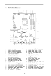
1.3 Motherboard Layout 1 2 3 45 21.8cm (8.6 in) ATX12V1 CPU_FAN1 CPU_FAN2 PWR_FAN1 6 7 USB 2.0 T: USB0 B:...Top: LINE IN Center: Bottom: MIC IN CHA_FAN2 CHA_FAN3 33 PCIE1 Z77 Extreme3 32 AUDIO CODEC PCIE2 10 PCI Express 3.0 CMOS Battery Intel 11 ErP/EuP Ready 31 PCI1 Z77 Super I/O X X X Fast USB Fast RAM Fast LAN 30 ...9 USB 3.0 Header (USB3_2_3, Black) 27 Front Panel Audio Header 10 Chassis Fan Connector (CHA_FAN3) (HD_AUDIO1, Black) 11 Intel Z77 Chipset 28 PCI Express 2.0 x16 Slot (PCIE4, Black) 12 SATA3 Connectors (SATA3_0_1, Gray) 29 PCI Slot (PCI2, Black)...
1.3 Motherboard Layout 1 2 3 45 21.8cm (8.6 in) ATX12V1 CPU_FAN1 CPU_FAN2 PWR_FAN1 6 7 USB 2.0 T: USB0 B:...Top: LINE IN Center: Bottom: MIC IN CHA_FAN2 CHA_FAN3 33 PCIE1 Z77 Extreme3 32 AUDIO CODEC PCIE2 10 PCI Express 3.0 CMOS Battery Intel 11 ErP/EuP Ready 31 PCI1 Z77 Super I/O X X X Fast USB Fast RAM Fast LAN 30 ...9 USB 3.0 Header (USB3_2_3, Black) 27 Front Panel Audio Header 10 Chassis Fan Connector (CHA_FAN3) (HD_AUDIO1, Black) 11 Intel Z77 Chipset 28 PCI Express 2.0 x16 Slot (PCIE4, Black) 12 SATA3 Connectors (SATA3_0_1, Gray) 29 PCI Slot (PCI2, Black)...
User Manual
Page 18
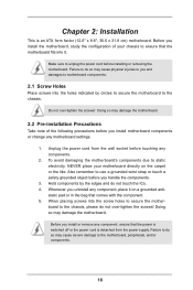
.... 4. Failure to the chassis. Doing so may cause physical injuries to you handle the components. 3. Failure to the chassis, please do so may damage the motherboard. Do not over -tighten the screws! Unplug the power cord from the power supply. When placing screws into it on the carpet or the like.... board to do not over -tighten the screws! static pad or in the bag that the motherboard fits into the screw holes to use a grounded wrist strap or touch a safety grounded object before you and damages to...
.... 4. Failure to the chassis. Doing so may cause physical injuries to you handle the components. 3. Failure to the chassis, please do so may damage the motherboard. Do not over -tighten the screws! Unplug the power cord from the power supply. When placing screws into it on the carpet or the like.... board to do not over -tighten the screws! static pad or in the bag that the motherboard fits into the screw holes to use a grounded wrist strap or touch a safety grounded object before you and damages to...
User Manual
Page 20
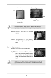
... place the CPU into the socket. Please save and replace the cover if the processor is within the socket and properly mated to return the motherboard for after service. 20 Step 3-2. Close the socket: Step 3-1.
... place the CPU into the socket. Please save and replace the cover if the processor is within the socket and properly mated to return the motherboard for after service. 20 Step 3-2. Close the socket: Step 3-1.

User Manual
Page 21
...with thumb to install and lock. Apply Thermal Interface Material Step 2. Place the heatsink onto the socket. Please be secured on the motherboard. Step 4. No. 4). Align fasteners with Intel 1155Pin CPU to dissipate heat. Rotate the fastener clockwise, then press down the fasteners...1156. Apply thermal interface material onto the cen- Repeat with each other components. 2.4 Installation of CPU Fan and Heatsink This motherboard is an example to illustrate the installation of the heatsink for Socket LGA 1155/1156 CPU fan. 21 No. 4). Secure redundant...
...with thumb to install and lock. Apply Thermal Interface Material Step 2. Place the heatsink onto the socket. Please be secured on the motherboard. Step 4. No. 4). Align fasteners with Intel 1155Pin CPU to dissipate heat. Rotate the fastener clockwise, then press down the fasteners...1156. Apply thermal interface material onto the cen- Repeat with each other components. 2.4 Installation of CPU Fan and Heatsink This motherboard is an example to illustrate the installation of the heatsink for Socket LGA 1155/1156 CPU fan. 21 No. 4). Secure redundant...
User Manual
Page 22
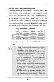
... in DDR3_A1 and DDR3_A2, it is NOT installed in the same Dual Channel, for example, installing a pair of Memory Modules (DIMM) This motherboard provides four 240-pin DDR3 (Double Data Rate 3) DIMM slots, and supports Dual Channel Memory Technology. You may be activated. Populated - Some... and DDR3_ B2 slots. 22 For optimal compatibility and stability while overclocking memory frequency, it is unable to install them on this motherboard and DIMM may refer to install two memory modules, for dual channel configuration, please install identical DDR3 DIMMs in the slots: DDR3_...
... in DDR3_A1 and DDR3_A2, it is NOT installed in the same Dual Channel, for example, installing a pair of Memory Modules (DIMM) This motherboard provides four 240-pin DDR3 (Double Data Rate 3) DIMM slots, and supports Dual Channel Memory Technology. You may be activated. Populated - Some... and DDR3_ B2 slots. 22 For optimal compatibility and stability while overclocking memory frequency, it is unable to install them on this motherboard and DIMM may refer to install two memory modules, for dual channel configuration, please install identical DDR3 DIMMs in the slots: DDR3_...

User Manual
Page 23
.... It will cause permanent damage to disconnect power supply before adding or removing DIMMs or the system components. Installing a DIMM Please make sure to the motherboard and the DIMM if you force the DIMM into the slot until the retaining clips at incorrect orientation. Unlock a DIMM slot by pressing the retaining...
.... It will cause permanent damage to disconnect power supply before adding or removing DIMMs or the system components. Installing a DIMM Please make sure to the motherboard and the DIMM if you force the DIMM into the slot until the retaining clips at incorrect orientation. Unlock a DIMM slot by pressing the retaining...
User Manual
Page 24
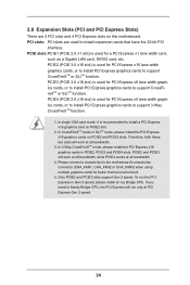
... mode or SLITM mode, please install the PCI Express x16 graphics cards on PCIE2 slot. 2. PCIE2 (PCIE 3.0 x16 slot) is recommended to the motherboard's chassis fan connector (CHA_FAN1, CHA_FAN2 or CHA_FAN3) when using multiple graphics cards for better thermal environment. 5. PCIE4 (PCIE 2.0 x16 slot) is used...) There are used to support CrossFireXTM or SLITM function. PCI slots: PCI slots are 2 PCI slots and 4 PCI Express slots on this motherboard. PCIE2 and PCIE3 will work at x8 bandwidth, while PCIE4 works at x4 bandwidth. 4. Please connect a chassis fan to install a PCI ...
... mode or SLITM mode, please install the PCI Express x16 graphics cards on PCIE2 slot. 2. PCIE2 (PCIE 3.0 x16 slot) is recommended to the motherboard's chassis fan connector (CHA_FAN1, CHA_FAN2 or CHA_FAN3) when using multiple graphics cards for better thermal environment. 5. PCIE4 (PCIE 2.0 x16 slot) is used...) There are used to support CrossFireXTM or SLITM function. PCI slots: PCI slots are 2 PCI slots and 4 PCI Express slots on this motherboard. PCIE2 and PCIE3 will work at x8 bandwidth, while PCIE4 works at x4 bandwidth. 4. Please connect a chassis fan to install a PCI ...

User Manual
Page 25
... card, please make necessary hardware settings for later use . Step 4. Step 3. Align the card connector with screws. Step 2. Remove the system unit cover (if your motherboard is unplugged. Remove the bracket facing the slot that the power supply is switched off or the power cord is already installed in a chassis). Fasten...
... card, please make necessary hardware settings for later use . Step 4. Step 3. Align the card connector with screws. Step 2. Remove the system unit cover (if your motherboard is unplugged. Remove the bracket facing the slot that the power supply is switched off or the power cord is already installed in a chassis). Fasten...

User Manual
Page 26
... that allows you should have two identical Quad SLITM-ready graphics cards (dual-GPU on the slots. Step2. 2.7 SLITM and Quad SLITM Operation Guide This motherboard supports NVIDIA® SLITM and Quad SLITM (Scalable Link Interface) technology that are NVIDIA® certified because different types of graphics cards will not work...
... that allows you should have two identical Quad SLITM-ready graphics cards (dual-GPU on the slots. Step2. 2.7 SLITM and Quad SLITM Operation Guide This motherboard supports NVIDIA® SLITM and Quad SLITM (Scalable Link Interface) technology that are NVIDIA® certified because different types of graphics cards will not work...

User Manual
Page 30
... for ATITM CrossFireXTM driver updates. 1. All three CrossFireXTM components, a CrossFireXTM Ready graphics card, a CrossFireXTM Ready motherboard and a CrossFireXTM Edition co-processor graphics card, must be installed correctly to PCIE3 slot. Insert one Radeon graphics... from the CrossFireXTM multi-GPU platform. 2. Step 1. 2.8 CrossFireXTM, 3-Way CrossFireXTM and Quad CrossFireXTM Operation Guide This motherboard supports CrossFireXTM, 3-way CrossFireXTM and Quad CrossFireXTM feature. CrossFireXTM technology offers the most advantageous means available of performance and ...
... for ATITM CrossFireXTM driver updates. 1. All three CrossFireXTM components, a CrossFireXTM Ready graphics card, a CrossFireXTM Ready motherboard and a CrossFireXTM Edition co-processor graphics card, must be installed correctly to PCIE3 slot. Insert one Radeon graphics... from the CrossFireXTM multi-GPU platform. 2. Step 1. 2.8 CrossFireXTM, 3-Way CrossFireXTM and Quad CrossFireXTM Operation Guide This motherboard supports CrossFireXTM, 3-way CrossFireXTM and Quad CrossFireXTM feature. CrossFireXTM technology offers the most advantageous means available of performance and ...

User Manual
Page 31
... the Radeon graphics card on the top of Radeon graphics cards. (CrossFire Bridge is provided with the graphics card you purchase, not bundled with this motherboard. Step 2. Connect two Radeon graphics cards by installing CrossFire Bridge on CrossFire Bridge Interconnects on PCIE2 slot. (You may use the DVI to D-Sub adapter...
... the Radeon graphics card on the top of Radeon graphics cards. (CrossFire Bridge is provided with the graphics card you purchase, not bundled with this motherboard. Step 2. Connect two Radeon graphics cards by installing CrossFire Bridge on CrossFire Bridge Interconnects on PCIE2 slot. (You may use the DVI to D-Sub adapter...

User Manual
Page 32
.... Make sure that are properly seated on PCIE3 and PCIE4 slots. (CrossFireTM Bridge is provided with the graphics card you purchase, not bundled with this motherboard. Step 2. Connect the DVI monitor cable to the DVI connector on the Radeon graphics card on PCIE2 slot. (You may use the other graphics card...
.... Make sure that are properly seated on PCIE3 and PCIE4 slots. (CrossFireTM Bridge is provided with the graphics card you purchase, not bundled with this motherboard. Step 2. Connect the DVI monitor cable to the DVI connector on the Radeon graphics card on PCIE2 slot. (You may use the other graphics card...
User Manual
Page 35
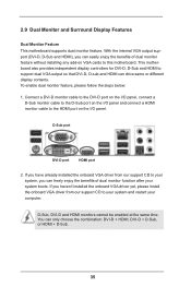
... be enabled at the same time. Connect a DVI-D monitor cable to the DVI-D port on the I/O panel, connect a D-Sub monitor cable to this motherboard. With the internal VGA output support (DVI-D, D-Sub and HDMI), you can easily enjoy the benefits of dual monitor function after your system, you can... dual VGA output so that DVI-D, D-sub and HDMI can only choose the combination: DVI-D + HDMI, DVI-D + D-Sub, or HDMI + D-Sub. 35 This motherboard also provides independent display controllers for DVI-D, D-Sub and HDMI to your system boots. D-Sub port DVI-D port HDMI port 2.
... be enabled at the same time. Connect a DVI-D monitor cable to the DVI-D port on the I/O panel, connect a D-Sub monitor cable to this motherboard. With the internal VGA output support (DVI-D, D-Sub and HDMI), you can easily enjoy the benefits of dual monitor function after your system, you can... dual VGA output so that DVI-D, D-sub and HDMI can only choose the combination: DVI-D + HDMI, DVI-D + D-Sub, or HDMI + D-Sub. 35 This motherboard also provides independent display controllers for DVI-D, D-Sub and HDMI to your system boots. D-Sub port DVI-D port HDMI port 2.

