User Manual
Page 5
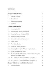
...1.3 Motherboard Layout 6 1.4 I/O Panel 8 Chapter 2 Installation 10 2.1 Installing the CPU 11 2.2 Installing the CPU Fan and Heatsink 14 2.3 Installing Memory Modules (DIMM) 15 2.4 Expansion Slots (PCIe Slots) 17 2.5 Onboard Headers and Connectors 18 2.6 Smart Switch 24 2.7 Post Status Checker 25 2.8 CrossFireTM Operation Guide 26 2.8.1 Installing Two CrossFireTM-Ready Graphics Cards 26 2.8.2 Driver Installation and Setup 28 2.9 M.2 WiFi/BT PCIe WiFi Module and Intel® CNVi (Integrated WiFi/BT) Installation Guide 29 2.10 M.2_SSD (NGFF) Module Installation Guide...
...1.3 Motherboard Layout 6 1.4 I/O Panel 8 Chapter 2 Installation 10 2.1 Installing the CPU 11 2.2 Installing the CPU Fan and Heatsink 14 2.3 Installing Memory Modules (DIMM) 15 2.4 Expansion Slots (PCIe Slots) 17 2.5 Onboard Headers and Connectors 18 2.6 Smart Switch 24 2.7 Post Status Checker 25 2.8 CrossFireTM Operation Guide 26 2.8.1 Installing Two CrossFireTM-Ready Graphics Cards 26 2.8.2 Driver Installation and Setup 28 2.9 M.2 WiFi/BT PCIe WiFi Module and Intel® CNVi (Integrated WiFi/BT) Installation Guide 29 2.10 M.2_SSD (NGFF) Module Installation Guide...
User Manual
Page 9
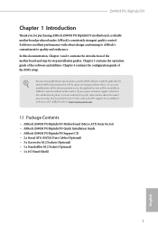
...(Micro ATX Form Factor) • ASRock Z690M PG Riptide/D5 Quick Installation Guide • ASRock Z690M PG Riptide/D5 Support CD • 2 x Serial ATA (SATA) Data Cables (Optional) • 3 x Screws for M.2 Sockets (Optional) • 1 x Standoff for specific information about the model you are using. In case any modifications of this documentation, Chapter 1 and 2 contains the introduction of this motherboard, please visit our website for M.2 Socket (Optional) • 1 x I/O Panel Shield 1 English Chapter 3 contains the operation guide of the BIOS setup. Z690M PG Riptide/D5...
...(Micro ATX Form Factor) • ASRock Z690M PG Riptide/D5 Quick Installation Guide • ASRock Z690M PG Riptide/D5 Support CD • 2 x Serial ATA (SATA) Data Cables (Optional) • 3 x Screws for M.2 Sockets (Optional) • 1 x Standoff for specific information about the model you are using. In case any modifications of this documentation, Chapter 1 and 2 contains the introduction of this motherboard, please visit our website for M.2 Socket (Optional) • 1 x I/O Panel Shield 1 English Chapter 3 contains the operation guide of the BIOS setup. Z690M PG Riptide/D5...
User Manual
Page 11
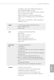
.../LINK LED and SPEED LED) • 1 x BIOS Flashback Button • HD Audio Jacks: Line in / Front Speaker / Microphone Storage • 4 x SATA3 6.0 Gb/s Connectors • 1 x Hyper M.2 Socket (M2_1, Key M), supports type 2260/2280 PCIe Gen4x4 (64 Gb/s) mode* • 1 x Hyper M.2 Socket (M2_2, Key M), supports type 2230/2242/2260/2280 SATA3 6.0 Gb/s & PCIe Gen4x4 (64 Gb/s) modes* 3 English resolution up to 8K (7680x4320) @ 60Hz / 5K (5120x3200) @ 120Hz • Supports HDCP 2.3 with HDMI 2.1 TMDS Compatible and DisplayPort 1.4 Ports Audio...
.../LINK LED and SPEED LED) • 1 x BIOS Flashback Button • HD Audio Jacks: Line in / Front Speaker / Microphone Storage • 4 x SATA3 6.0 Gb/s Connectors • 1 x Hyper M.2 Socket (M2_1, Key M), supports type 2260/2280 PCIe Gen4x4 (64 Gb/s) mode* • 1 x Hyper M.2 Socket (M2_2, Key M), supports type 2230/2242/2260/2280 SATA3 6.0 Gb/s & PCIe Gen4x4 (64 Gb/s) modes* 3 English resolution up to 8K (7680x4320) @ 60Hz / 5K (5120x3200) @ 120Hz • Supports HDCP 2.3 with HDMI 2.1 TMDS Compatible and DisplayPort 1.4 Ports Audio...
User Manual
Page 13
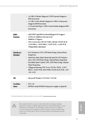
...Z690M PG Riptide/D5 BIOS Feature Hardware Monitor OS Certifications • 1 x USB 2.0 Header (Supports 2 USB 2.0 ports) (Supports ESD Protection) • 1 x USB 3.2 Gen1 Header (Supports 2 USB 3.2 Gen1 ports) (Supports ESD Protection) • 1 x Front Panel Type C USB 3.2 Gen1 Header (Supports ESD Protection) • AMI UEFI Legal BIOS with multilingual GUI support • ACPI 6.0 Compliant wake up events • SMBIOS 2.7 Support • CPU Core/Cache, CPU GT, VDD2, DRAM, VCCIN AUX, +1.8V PROC, +1.05V PROC, +0.82V PCH , +1.05V PCH Voltage Multi-adjustment • Fan Tachometer: CPU...
...Z690M PG Riptide/D5 BIOS Feature Hardware Monitor OS Certifications • 1 x USB 2.0 Header (Supports 2 USB 2.0 ports) (Supports ESD Protection) • 1 x USB 3.2 Gen1 Header (Supports 2 USB 3.2 Gen1 ports) (Supports ESD Protection) • 1 x Front Panel Type C USB 3.2 Gen1 Header (Supports ESD Protection) • AMI UEFI Legal BIOS with multilingual GUI support • ACPI 6.0 Compliant wake up events • SMBIOS 2.7 Support • CPU Core/Cache, CPU GT, VDD2, DRAM, VCCIN AUX, +1.8V PROC, +1.05V PROC, +0.82V PCH , +1.05V PCH Voltage Multi-adjustment • Fan Tachometer: CPU...
User Manual
Page 15
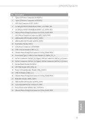
... SATA3 Connector (SATA3_0) (Upper), SATA3 Connector (SATA3_1) (Lower) 16 SATA3 Connector (SATA3_2) (Upper), SATA3 Connector (SATA3_3) (Lower) 17 System Panel Header (PANEL1) 18 SPI TPM Header (SPI_TPM_J1) 19 Power LED and Speaker Header (SPK_PLED1) 20 USB 2.0 Header (USB_0_1) 21 Chassis/Water Pump Fan Connector (CHA_FAN4/WP) 22 RGB LED Header (RGB_LED1) 23 Addressable LED Header (ADDR_LED1) 24 5-pin Thunderbolt AIC Connector (TB1) 25 Front Panel Audio Header (HD_AUDIO1) 26 Chassis/Water Pump Fan Connector (CHA_FAN2/WP) 7 English Z690M PG Riptide/D5 No...
... SATA3 Connector (SATA3_0) (Upper), SATA3 Connector (SATA3_1) (Lower) 16 SATA3 Connector (SATA3_2) (Upper), SATA3 Connector (SATA3_3) (Lower) 17 System Panel Header (PANEL1) 18 SPI TPM Header (SPI_TPM_J1) 19 Power LED and Speaker Header (SPK_PLED1) 20 USB 2.0 Header (USB_0_1) 21 Chassis/Water Pump Fan Connector (CHA_FAN4/WP) 22 RGB LED Header (RGB_LED1) 23 Addressable LED Header (ADDR_LED1) 24 5-pin Thunderbolt AIC Connector (TB1) 25 Front Panel Audio Header (HD_AUDIO1) 26 Chassis/Water Pump Fan Connector (CHA_FAN2/WP) 7 English Z690M PG Riptide/D5 No...
User Manual
Page 23
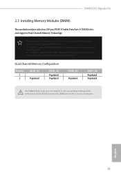
... three memory module installed. 3. For dual channel configuration, you force the DIMM into a DDR5 slot; It is unable to install identical (the same brand, speed, size and chip-type) DDR5 DIMM pairs. 2. Z690M PG Riptide/D5 2.3 Installing Memory Modules (DIMM) This motherboard provides four 288-pin DDR5 (Double Data Rate 5) DIMM slots, and supports Dual Channel Memory Technology. 1. It will cause permanent damage to the motherboard and the DIMM if you always need to activate Dual Channel Memory Technology with...
... three memory module installed. 3. For dual channel configuration, you force the DIMM into a DDR5 slot; It is unable to install identical (the same brand, speed, size and chip-type) DDR5 DIMM pairs. 2. Z690M PG Riptide/D5 2.3 Installing Memory Modules (DIMM) This motherboard provides four 288-pin DDR5 (Double Data Rate 5) DIMM slots, and supports Dual Channel Memory Technology. 1. It will cause permanent damage to the motherboard and the DIMM if you always need to activate Dual Channel Memory Technology with...
User Manual
Page 25
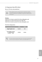
... slot) is used for PCIe x1 lane width cards. PCIE3 (PCIe 4.0 x16 slot) is unplugged. English 17 Before installing an expansion card, please make necessary hardware settings for PCIe x16 lane width graphics cards. Please read the documentation of the expansion card and make sure that the power supply is switched off or the power cord is used for the card before you start the installation. Z690M PG Riptide/D5 2.4 Expansion Slots (PCIe Slots) There are 3 PCIe slots on the motherboard...
... slot) is used for PCIe x1 lane width cards. PCIE3 (PCIe 4.0 x16 slot) is unplugged. English 17 Before installing an expansion card, please make necessary hardware settings for PCIe x16 lane width graphics cards. Please read the documentation of the expansion card and make sure that the power supply is switched off or the power cord is used for the card before you start the installation. Z690M PG Riptide/D5 2.4 Expansion Slots (PCIe Slots) There are 3 PCIe slots on the motherboard...
User Manual
Page 27
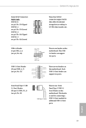
... Header (20-pin F_USB3_TC_1) (see p.6, No. 14) USB Type-C Cable There is one header on this motherboard. Vbus IntA_PA_SSRXIntA_PA_SSRX+ GND IntA_PA_SSTXIntA_PA_SSTX+ GND IntA_PA_DIntA_PA_D+ Vbus IntA_PB_SSRXIntA_PB_SSRX+ GND IntA_PB_SSTXIntA_PB_SSTX+ GND IntA_PB_DIntA_PB_D+ Dummy 1 There are two headers on this motherboard. Each USB 3.2 Gen1 header can support two ports. This header is used for connecting a USB 3.2 Gen1 module for internal storage devices with up to 6.0 Gb/s data transfer rate. This USB 2.0 header can support two ports. English 19 Z690M PG Riptide/D5 Serial...
... Header (20-pin F_USB3_TC_1) (see p.6, No. 14) USB Type-C Cable There is one header on this motherboard. Vbus IntA_PA_SSRXIntA_PA_SSRX+ GND IntA_PA_SSTXIntA_PA_SSTX+ GND IntA_PA_DIntA_PA_D+ Vbus IntA_PB_SSRXIntA_PB_SSRX+ GND IntA_PB_SSTXIntA_PB_SSTX+ GND IntA_PB_DIntA_PB_D+ Dummy 1 There are two headers on this motherboard. Each USB 3.2 Gen1 header can support two ports. This header is used for connecting a USB 3.2 Gen1 module for internal storage devices with up to 6.0 Gb/s data transfer rate. This USB 2.0 header can support two ports. English 19 Z690M PG Riptide/D5 Serial...
User Manual
Page 29
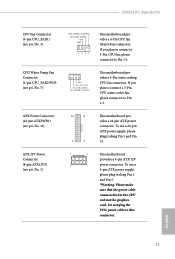
To use a 4-pin ATX power supply, please plug it along Pin 1 and Pin 5. *Warning: Please make sure that the power cable connected is for the CPU and not the graphics card. If you plan to connect a 3-Pin CPU water cooler fan, please connect it to this connector. English 21 Do not plug the PCIe power cable to Pin 1-3. 4 3 21 GND FAN_VOLTAGE CPU_FAN_SPEED FAN_SPEED_CONTROL This motherboard provides a 4-Pin water cooling CPU fan connector. Z690M PG Riptide/D5 CPU Fan Connector (4-pin CPU_FAN1) (see p.6, No. 3) CPU/Water Pump Fan Connector (4-pin CPU_FAN2/WP) (see p.6, ...
To use a 4-pin ATX power supply, please plug it along Pin 1 and Pin 5. *Warning: Please make sure that the power cable connected is for the CPU and not the graphics card. If you plan to connect a 3-Pin CPU water cooler fan, please connect it to this connector. English 21 Do not plug the PCIe power cable to Pin 1-3. 4 3 21 GND FAN_VOLTAGE CPU_FAN_SPEED FAN_SPEED_CONTROL This motherboard provides a 4-Pin water cooling CPU fan connector. Z690M PG Riptide/D5 CPU Fan Connector (4-pin CPU_FAN1) (see p.6, No. 3) CPU/Water Pump Fan Connector (4-pin CPU_FAN2/WP) (see p.6, ...
User Manual
Page 30
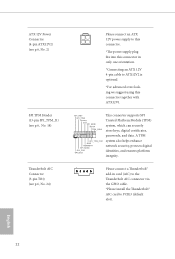
ATX 12V Power Connector (4-pin ATX12V2) (see p.6, No. 2) SPI TPM Header (13-pin SPI_TPM_J1) (see p.6, No. 18) Thunderbolt AIC Connector (5-pin TB1) (see p.6, No. 24) Please connect an ATX 12V power supply to this connector. *The power supply plug fits into this connector in card (AIC) to the Thunderbolt AIC connector via the GPIO cable. *Please install the Thunderbolt™ AIC card to ATX12V2 is optional. *For advanced overclocking we suggest using this connector together with ATX12V1...
ATX 12V Power Connector (4-pin ATX12V2) (see p.6, No. 2) SPI TPM Header (13-pin SPI_TPM_J1) (see p.6, No. 18) Thunderbolt AIC Connector (5-pin TB1) (see p.6, No. 24) Please connect an ATX 12V power supply to this connector. *The power supply plug fits into this connector in card (AIC) to the Thunderbolt AIC connector via the GPIO cable. *Please install the Thunderbolt™ AIC card to ATX12V2 is optional. *For advanced overclocking we suggest using this connector together with ATX12V1...
User Manual
Page 32
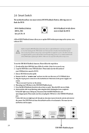
... the LED light turns solid green, this means that you plug the USB drive to disable fTPM before updating the BIOS. Reconnect power and battery and try again. It is no need to power on the power supply's AC switch. *There is recommended to the USB BIOS Flashback port. **If the LED does not light up at all then please disconnect power from the system and remove/ disconnect the CMOS battery from the motherboard for...
... the LED light turns solid green, this means that you plug the USB drive to disable fTPM before updating the BIOS. Reconnect power and battery and try again. It is no need to power on the power supply's AC switch. *There is recommended to the USB BIOS Flashback port. **If the LED does not light up at all then please disconnect power from the system and remove/ disconnect the CMOS battery from the motherboard for...
User Manual
Page 34
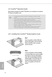
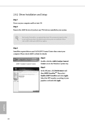
... your graphics card driver supports AMD CrossFireTM technology. CrossFire Bridge Step 2 Connect two graphics cards by installing a CrossFire Bridge on the CrossFire Bridge Interconnects on the slots. You should only use a AMD certified PSU. If you to install up to enable CrossFireTM. Different CrossFireTM cards may require different methods to two identical PCI Express x16 graphics cards. 1. Download the drivers from the AMD's website: www.amd.com 3. 2.8 CrossFireTM Operation Guide This motherboard supports CrossFireTM that your power supply unit...
... your graphics card driver supports AMD CrossFireTM technology. CrossFire Bridge Step 2 Connect two graphics cards by installing a CrossFire Bridge on the CrossFire Bridge Interconnects on the slots. You should only use a AMD certified PSU. If you to install up to enable CrossFireTM. Different CrossFireTM cards may require different methods to two identical PCI Express x16 graphics cards. 1. Download the drivers from the AMD's website: www.amd.com 3. 2.8 CrossFireTM Operation Guide This motherboard supports CrossFireTM that your power supply unit...
User Manual
Page 36
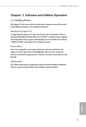
... any VGA drivers installed in the Windows® system tray. Please check AMD's website for details. Please check AMD's website for AMD driver updates. The Catalyst Uninstaller is an optional download. AMD Catalyst Control Center Step 4 Double-click the AMD Catalyst Control Center icon in your computer and boot into OS. English 28 Step 5 In the left pane, click Performance and then AMD CrossFireTM. 2.8.2 Driver Installation and Setup Step 1 Power on...
... any VGA drivers installed in the Windows® system tray. Please check AMD's website for details. Please check AMD's website for AMD driver updates. The Catalyst Uninstaller is an optional download. AMD Catalyst Control Center Step 4 Double-click the AMD Catalyst Control Center icon in your computer and boot into OS. English 28 Step 5 In the left pane, click Performance and then AMD CrossFireTM. 2.8.2 Driver Installation and Setup Step 1 Power on...

User Manual
Page 39
B A No. Nut Location PCB Length Module Type 1 A 6cm Type2260 2 B 8cm Type 2280 English 31 The Hyper M.2 Socket (M2_1, Key M) supports type 2260/2280 PCIe Gen4x4 (64 Gb/s) mode. Z690M PG Riptide/D5 2.10 M.2_SSD (NGFF) Module Installation Guide (M2_1) The M.2, also known as the Next Generation Form Factor (NGFF), is a small size and versatile card edge connector that aims to be used. Installing the M.2_SSD (NGFF) Module Step 1 Prepare a M.2_SSD (NGFF...
B A No. Nut Location PCB Length Module Type 1 A 6cm Type2260 2 B 8cm Type 2280 English 31 The Hyper M.2 Socket (M2_1, Key M) supports type 2260/2280 PCIe Gen4x4 (64 Gb/s) mode. Z690M PG Riptide/D5 2.10 M.2_SSD (NGFF) Module Installation Guide (M2_1) The M.2, also known as the Next Generation Form Factor (NGFF), is a small size and versatile card edge connector that aims to be used. Installing the M.2_SSD (NGFF) Module Step 1 Prepare a M.2_SSD (NGFF...
User Manual
Page 47
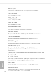
Utilities Menu The Utilities Menu shows the application software that enhance the motherboard's features. Drivers Menu The drivers compatible to your system will be auto-detected and listed on a specific item then follow the order from top to bottom to install those required drivers. Therefore, the drivers you install can work properly. If the Main Menu does not appear automatically, locate and double click on the file "ASRSETUP.EXE" in your CD-ROM drive. Click...
Utilities Menu The Utilities Menu shows the application software that enhance the motherboard's features. Drivers Menu The drivers compatible to your system will be auto-detected and listed on a specific item then follow the order from top to bottom to install those required drivers. Therefore, the drivers you install can work properly. If the Main Menu does not appear automatically, locate and double click on the file "ASRSETUP.EXE" in your CD-ROM drive. Click...
User Manual
Page 90
... graphics processor when the system boots up. Set to Auto to disable the integrated graphics when an external graphics card is allocated to keep the integrated graphics enabled at all PCH DMI devices. PCH DMI ASPM Support This option enables/disables the ASPM support for all CPU downstream devices. IGPU Multi-Monitor Select disable to enable onboard HD audio and automatically disable it when a sound card is optimizing for all PCH PCIE devices. DMI Link Speed Configure DMI Slot Link Speed. PCI Express Native Control Select Enable...
... graphics processor when the system boots up. Set to Auto to disable the integrated graphics when an external graphics card is allocated to keep the integrated graphics enabled at all PCH DMI devices. PCH DMI ASPM Support This option enables/disables the ASPM support for all CPU downstream devices. IGPU Multi-Monitor Select disable to enable onboard HD audio and automatically disable it when a sound card is optimizing for all PCH PCIE devices. DMI Link Speed Configure DMI Slot Link Speed. PCI Express Native Control Select Enable...
User Manual
Page 97
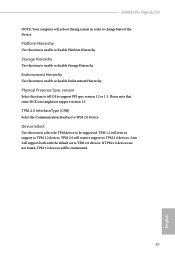
... supported. Platform Hierarchy Use this item to tell OS to support PPI spec version 1.2 or 1.3. Z690M PG Riptide/D5 NOTE: Your computer will support both with the default set to TPM 2.0 devices. Please note that some HCK tests might not support version 1.3. Auto will reboot during restart in order to change State of the Device. Endorsement Hierarchy Use this item to enable or disable Endorsement Hierarchy. Storage Hierarchy Use this item to enable or disable Storage...
... supported. Platform Hierarchy Use this item to tell OS to support PPI spec version 1.2 or 1.3. Z690M PG Riptide/D5 NOTE: Your computer will support both with the default set to TPM 2.0 devices. Please note that some HCK tests might not support version 1.3. Auto will reboot during restart in order to change State of the Device. Endorsement Hierarchy Use this item to enable or disable Endorsement Hierarchy. Storage Hierarchy Use this item to enable or disable Storage...

User Manual
Page 99
Internet Setting Enable or disable sound effects in your USB pen drive before using this to configure internet connection settings for you. Please setup network configuration before using Internet Flash. *For BIOS backup and recovery purpose, it is recommended to download the UEFI firmware. 91 English DHCP (Auto IP), Auto ASRock Internet Flash downloads and updates the latest UEFI firmware version from our servers for Internet Flash. Network Configuration Use this function. UEFI Download Server Select a server to plug in the setup utility. Z690M PG Riptide/D5 Internet Flash -...
Internet Setting Enable or disable sound effects in your USB pen drive before using this to configure internet connection settings for you. Please setup network configuration before using Internet Flash. *For BIOS backup and recovery purpose, it is recommended to download the UEFI firmware. 91 English DHCP (Auto IP), Auto ASRock Internet Flash downloads and updates the latest UEFI firmware version from our servers for Internet Flash. Network Configuration Use this function. UEFI Download Server Select a server to plug in the setup utility. Z690M PG Riptide/D5 Internet Flash -...
User Manual
Page 104
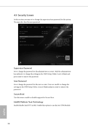
... and press enter to remove the password. Supervisor Password Set or change the password for the administrator account. User Password Set or change the password for the user account. Users are unable to enable or disable support for the system. Only the administrator has authority to use discrete TPM Module. 96 English Secure Boot Use this option to change the settings in ME. Intel(R) Platform Trust Technology Enable/disable Intel PTT in the UEFI Setup Utility. 4.9 Security Screen In this...
... and press enter to remove the password. Supervisor Password Set or change the password for the administrator account. User Password Set or change the password for the user account. Users are unable to enable or disable support for the system. Only the administrator has authority to use discrete TPM Module. 96 English Secure Boot Use this option to change the settings in ME. Intel(R) Platform Trust Technology Enable/disable Intel PTT in the UEFI Setup Utility. 4.9 Security Screen In this...
Intel Rapid Storage Guide
Page 13
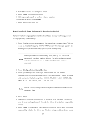
... you see a message in the status line that says, Please insert the disk labeled Manufacturer-supplied hardware support disk into Drive A:, insert ;a floppy disk containing the following steps to confirm your controller from the list of Windows setup (during operating system setup: 1. Press Enter. 5. Install the RAID Driver Using the F6 Installation Method Perform the following files: IAAHCI.INF, IAAHCI.CAT, IASTOR.INF, IASTOR.CAT, IASTOR.SYS, and TXTSETUP...
... you see a message in the status line that says, Please insert the disk labeled Manufacturer-supplied hardware support disk into Drive A:, insert ;a floppy disk containing the following steps to confirm your controller from the list of Windows setup (during operating system setup: 1. Press Enter. 5. Install the RAID Driver Using the F6 Installation Method Perform the following files: IAAHCI.INF, IAAHCI.CAT, IASTOR.INF, IASTOR.CAT, IASTOR.SYS, and TXTSETUP...


