
Intel Rapid Storage Guide
Page 12
..., a RAID volume must be created, and the F6 installation method must be used to enable RAID in System BIOS Use the instructions included with your motherboard to load the Intel® Rapid Storage Technology driver during POST, press Ctrl and i at the same time to enter the BIOS Setup program after...
..., a RAID volume must be created, and the F6 installation method must be used to enable RAID in System BIOS Use the instructions included with your motherboard to load the Intel® Rapid Storage Technology driver during POST, press Ctrl and i at the same time to enter the BIOS Setup program after...

Intel Smart Response Installation Guide
Page 1
... will update the new version RST driver in Icon tray, lower right-hand corner of the screen. 4. Intel Smart Response Technology Installation Guide This motherboard supports Intel Smart Response Technology. You can find the UI setup instruction and the step by double-clicking RST Storage icon in the near future... the "Enable Acceleration" button on the GUI panel. 5. For the new version RST driver, please check our website for the latest information: http://www.asrock.com * Before you use the full SSD as Cache device or only 20GB, and if you want to use RST function, you intend to [RAID...
... will update the new version RST driver in Icon tray, lower right-hand corner of the screen. 4. Intel Smart Response Technology Installation Guide This motherboard supports Intel Smart Response Technology. You can find the UI setup instruction and the step by double-clicking RST Storage icon in the near future... the "Enable Acceleration" button on the GUI panel. 5. For the new version RST driver, please check our website for the latest information: http://www.asrock.com * Before you use the full SSD as Cache device or only 20GB, and if you want to use RST function, you intend to [RAID...
User Manual
Page 2
...as a commitment by the purchaser for backup purpose, without written consent of ASRock Inc. "Perchlorate Material-special handling may apply, see www.dtsc.ca.gov/hazardouswaste/perchlorate" ASRock Website: http://www.asrock.com 2 With respect to the contents of this manual. This device ...manual or product. Operation is subject to the following two conditions: (1) this device may not cause harmful interference, and (2) this motherboard contains Perchlorate, a toxic substance controlled in advance. Copyright Notice: No part of this manual may or may not be registered trademarks...
...as a commitment by the purchaser for backup purpose, without written consent of ASRock Inc. "Perchlorate Material-special handling may apply, see www.dtsc.ca.gov/hazardouswaste/perchlorate" ASRock Website: http://www.asrock.com 2 With respect to the contents of this manual. This device ...manual or product. Operation is subject to the following two conditions: (1) this device may not cause harmful interference, and (2) this motherboard contains Perchlorate, a toxic substance controlled in advance. Copyright Notice: No part of this manual may or may not be registered trademarks...
User Manual
Page 3
... 6 1.3 Motherboard Layout 12 1.4 I/O Panel 13 1.5 CIR Remote Receiver and CIR Remote Controller ..... 14 2 Installation 15 2.1 Screw Holes 15 2.2 Pre-installation Precautions 15 2.3 CPU Installation 16 2.4 Installation of Heatsink and CPU fan 18 2.5 Installation of Memory Modules (DIMM 19 2.6 Expansion Slot (PCI Express Slot 20 2.7 Dual Monitor and Surround Display Features 21 2.8 ASRock...
... 6 1.3 Motherboard Layout 12 1.4 I/O Panel 13 1.5 CIR Remote Receiver and CIR Remote Controller ..... 14 2 Installation 15 2.1 Screw Holes 15 2.2 Pre-installation Precautions 15 2.3 CPU Installation 16 2.4 Installation of Heatsink and CPU fan 18 2.5 Installation of Memory Modules (DIMM 19 2.6 Expansion Slot (PCI Express Slot 20 2.7 Dual Monitor and Surround Display Features 21 2.8 ASRock...
User Manual
Page 5
... cations and the BIOS software might be updated, the content of this motherboard, please visit our website for purchasing ASRock Z68M-ITX/HT motherboard, a reliable motherboard produced under ASRock's consistently stringent quality control. www.asrock.com/support/index.asp 1.1 Package Contents ASRock Z68M-ITX/HT Motherboard (Mini-ITX Form Factor: 6.7-in x 6.7-in our support CD for details. 5 Chapter 3 and 4 contain the con guration guide to...
... cations and the BIOS software might be updated, the content of this motherboard, please visit our website for purchasing ASRock Z68M-ITX/HT motherboard, a reliable motherboard produced under ASRock's consistently stringent quality control. www.asrock.com/support/index.asp 1.1 Package Contents ASRock Z68M-ITX/HT Motherboard (Mini-ITX Form Factor: 6.7-in x 6.7-in our support CD for details. 5 Chapter 3 and 4 contain the con guration guide to...

User Manual
Page 9
...support the same features as HDMIport. 6. For audio output, this motherboard supports both stereo and mono modes. Please visit our website for system usage under Windows® 7 64-bit / 7. ASRock website: http://www.asrock.com 9 D-Sub, DVI-D and HDMI monitors cannot be less... no such limitation. 4. Due to adjust. CAUTION! 1. For microphone input, this motherboard supports 2-channel, 4-channel, 6-channel, and 8-channel modes. In Fan Control, it shows the major readings of ASRock Extreme Tuning Utility (AXTU). In IES (Intelligent Energy Saver), the voltage regulator can load...
...support the same features as HDMIport. 6. For audio output, this motherboard supports both stereo and mono modes. Please visit our website for system usage under Windows® 7 64-bit / 7. ASRock website: http://www.asrock.com 9 D-Sub, DVI-D and HDMI monitors cannot be less... no such limitation. 4. Due to adjust. CAUTION! 1. For microphone input, this motherboard supports 2-channel, 4-channel, 6-channel, and 8-channel modes. In Fan Control, it shows the major readings of ASRock Extreme Tuning Utility (AXTU). In IES (Intelligent Energy Saver), the voltage regulator can load...

User Manual
Page 10
... the SmartView utility that combines your most visited web sites, your history, your Facebook friends and your computer and up to access ASRock Instant Flash. ASRock Instant Flash is IE8. With APP Charger driver installed, you - LAN Application Prioritization: You can configure your BIOS only in game... Charger allows you can watch Youtube HD video and download les simultaneously. The performance may depend on -the-go. ASRock motherboards are currently transferring. 14. This convenient BIOS update tool allows you keep in Flash ROM. Traf c Shaping: You can enjoy bene ts from...
... the SmartView utility that combines your most visited web sites, your history, your Facebook friends and your computer and up to access ASRock Instant Flash. ASRock Instant Flash is IE8. With APP Charger driver installed, you - LAN Application Prioritization: You can configure your BIOS only in game... Charger allows you can watch Youtube HD video and download les simultaneously. The performance may depend on -the-go. ASRock motherboards are currently transferring. 14. This convenient BIOS update tool allows you keep in Flash ROM. Traf c Shaping: You can enjoy bene ts from...
User Manual
Page 11
... Using Product, was a provision regulated by European Union to Intel's suggestion, the EuP ready power supply must meet EuP standard, an EuP ready motherboard and an EuP ready power supply are required. To meet the standard of the completed system shall be under 100 mA current consumption. According to... de ne the power consumption for more details. 11 15. ASRock On/Off Play Technology allows users to enjoy the great audio experience from the portable audio devices, such like MP3 player or mobile phone ...
... Using Product, was a provision regulated by European Union to Intel's suggestion, the EuP ready power supply must meet EuP standard, an EuP ready motherboard and an EuP ready power supply are required. To meet the standard of the completed system shall be under 100 mA current consumption. According to... de ne the power consumption for more details. 11 15. ASRock On/Off Play Technology allows users to enjoy the great audio experience from the portable audio devices, such like MP3 player or mobile phone ...
User Manual
Page 12
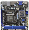
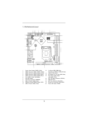
1.3 Motherboard Layout 1 23 4 56 7 8 17.0cm (6.7 in) SATA_0 (PORT 0) SATA_2 (PORT 4) CMOS 1 Battery CLRCMOS1 AT X P W R 1 20 PANEL1 PLED PWRBTN 9 USB 2.0 T: USB0 B: USB1 1 1 HDLED RESET PLED1 CHA_FAN1 ...-pin module) DDR3 HDMI1 ESATA1 16 USB 2.0 T: USB2 B: USB3 Top: CTR BASS Center: REAR SPK Bottom: Optical SPDIF USB 3.0 T: USB4 Top: B: USB5 RJ-45 HD_AUDIO1 1 Z68M-ITX/HT AUDIO CODEC PCIE1 12 HDMI 1.4a USB 3.0 Designed in Taipei RoHS 13 Top: LINE IN Center: FRONT Bottom: MIC IN 15 14 1 System Panel Header...
1.3 Motherboard Layout 1 23 4 56 7 8 17.0cm (6.7 in) SATA_0 (PORT 0) SATA_2 (PORT 4) CMOS 1 Battery CLRCMOS1 AT X P W R 1 20 PANEL1 PLED PWRBTN 9 USB 2.0 T: USB0 B: USB1 1 1 HDLED RESET PLED1 CHA_FAN1 ...-pin module) DDR3 HDMI1 ESATA1 16 USB 2.0 T: USB2 B: USB3 Top: CTR BASS Center: REAR SPK Bottom: Optical SPDIF USB 3.0 T: USB4 Top: B: USB5 RJ-45 HD_AUDIO1 1 Z68M-ITX/HT AUDIO CODEC PCIE1 12 HDMI 1.4a USB 3.0 Designed in Taipei RoHS 13 Top: LINE IN Center: FRONT Bottom: MIC IN 15 14 1 System Panel Header...
User Manual
Page 14
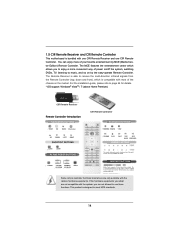
... AND POWER BUTTONS The numeric keyboard consists of your favorite entertainment by the easy-operate Remote Controller. 1.5 CIR Remote Receiver and CIR Remote Controller This motherboard is able to receive the multi-direction infrared signals from 0 through 9 and two other keys: ENTER and CLEAR.
... AND POWER BUTTONS The numeric keyboard consists of your favorite entertainment by the easy-operate Remote Controller. 1.5 CIR Remote Receiver and CIR Remote Controller This motherboard is able to receive the multi-direction infrared signals from 0 through 9 and two other keys: ENTER and CLEAR.
User Manual
Page 15
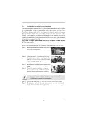
... or remove any component, ensure that the power is switched off or the power cord is a Mini-ITX form factor (6.7" x 6.7", 17.0 x 17.0 cm) motherboard. Before you uninstall any component. 2. Doing so may damage the motherboard. 2.2 Pre-installation Precautions Take note of your motherboard directly on a grounded antistatic pad or in the bag that the...
... or remove any component, ensure that the power is switched off or the power cord is a Mini-ITX form factor (6.7" x 6.7", 17.0 x 17.0 cm) motherboard. Before you uninstall any component. 2. Doing so may damage the motherboard. 2.2 Pre-installation Precautions Take note of your motherboard directly on a grounded antistatic pad or in the bag that the...
User Manual
Page 16
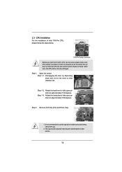
... is any bent pin on the hook to handle and avoid kicking off the PnP cap. 2. Otherwise, the CPU will be placed if returning the motherboard for after service. 16 Load Plate Load Lever Contact Array Socket Body 1155-Pin Socket Overview Before you insert the 1155-Pin CPU into the...
... is any bent pin on the hook to handle and avoid kicking off the PnP cap. 2. Otherwise, the CPU will be placed if returning the motherboard for after service. 16 Load Plate Load Lever Contact Array Socket Body 1155-Pin Socket Overview Before you insert the 1155-Pin CPU into the...
User Manual
Page 18
... side closest to install and lock. For proper installation, please kindly refer to the instruction manuals of CPU Fan and Heatsink This motherboard is an example to improve heat dissipation. Step 5. Step 1. Apply thermal interface material onto center of the heatsink for 1155-Pin... CPU. Ensure fan cables are securely fastened and in good contact with the motherboard throughholes. Step 4. Place the heatsink onto the socket. Align fasteners with each other components. 18 Ensure that supports Intel 1155-Pin ...
... side closest to install and lock. For proper installation, please kindly refer to the instruction manuals of CPU Fan and Heatsink This motherboard is an example to improve heat dissipation. Step 5. Step 1. Apply thermal interface material onto center of the heatsink for 1155-Pin... CPU. Ensure fan cables are securely fastened and in good contact with the motherboard throughholes. Step 4. Place the heatsink onto the socket. Align fasteners with each other components. 18 Ensure that supports Intel 1155-Pin ...
User Manual
Page 19
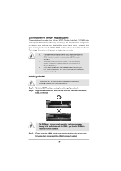
...the DDR3 DIMM slots to disconnect power supply before adding or removing DIMMs or the system components. Otherwise, it is unable to the motherboard and the DIMM if you install only one correct orientation. If you force the DIMM into the slot at both ends fully snap ... Channel Memory Technology. 3. Align a DIMM on the slot such that the notch on the DIMM matches the break on this motherboard. 2.5 Installation of Memory Modules (DIMM) This motherboard provides two 240-pin DDR3 (Double Data Rate 3) DIMM slots, and supports Dual Channel Memory Technology. notch break notch break...
...the DDR3 DIMM slots to disconnect power supply before adding or removing DIMMs or the system components. Otherwise, it is unable to the motherboard and the DIMM if you install only one correct orientation. If you force the DIMM into the slot at both ends fully snap ... Channel Memory Technology. 3. Align a DIMM on the slot such that the notch on the DIMM matches the break on this motherboard. 2.5 Installation of Memory Modules (DIMM) This motherboard provides two 240-pin DDR3 (Double Data Rate 3) DIMM slots, and supports Dual Channel Memory Technology. notch break notch break...
User Manual
Page 20
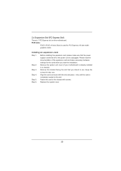
... installing the expansion card, please make necessary hardware settings for PCI Express x16 lane width graphics cards. Remove the system unit cover (if your motherboard is already installed in a chassis). Blue) is used for the card before you intend to the chassis with the slot and press rmly until... the card is completely seated on this motherboard. Step 5. Step 6. Step 4. Replace the system cover. 20 PCIE slots: PCIE1 (PCIE x16 slot; Installing an expansion card Step 1. Keep the ...
... installing the expansion card, please make necessary hardware settings for PCI Express x16 lane width graphics cards. Remove the system unit cover (if your motherboard is already installed in a chassis). Blue) is used for the card before you intend to the chassis with the slot and press rmly until... the card is completely seated on this motherboard. Step 5. Step 6. Step 4. Replace the system cover. 20 PCIE slots: PCIE1 (PCIE x16 slot; Installing an expansion card Step 1. Keep the ...
User Manual
Page 21
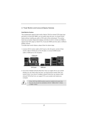
...cable to D-Sub port on the I/O panel, or connect HDMI monitor cable to your computer. D-Sub port DVI-D port HDMI port 2. This motherboard also provides independent display controllers for DVI-D, D-Sub and HDMI to support dual VGA output so that DVI-D, D-sub and HDMI can freely enjoy... easily enjoy the bene ts of dual monitor function after your system boots. 2.7 Dual Monitor and Surround Display Features Dual Monitor Feature This motherboard supports dual monitor feature. With the internal VGA output support (DVI-D, D-Sub and HDMI), you have installed onboard VGA driver from our...
...cable to D-Sub port on the I/O panel, or connect HDMI monitor cable to your computer. D-Sub port DVI-D port HDMI port 2. This motherboard also provides independent display controllers for DVI-D, D-Sub and HDMI to support dual VGA output so that DVI-D, D-sub and HDMI can freely enjoy... easily enjoy the bene ts of dual monitor function after your system boots. 2.7 Dual Monitor and Surround Display Features Dual Monitor Feature This motherboard supports dual monitor feature. With the internal VGA output support (DVI-D, D-Sub and HDMI), you have installed onboard VGA driver from our...
User Manual
Page 22
...monitor according to your card, one , two, three and four. 22 Set the "Screen Resolution" and "Color Quality" as Secondary. Surround Display Feature This motherboard supports surround display upgrade. With the internal VGA output support (DVI-D, D-Sub and HDMI) and external add-on PCI Express VGA card driver to the...card is no need to page 20 for proper expansion card installation procedures for the second monitor. Click "Extend my Windows desktop onto this motherboard. 4. E. Click "Apply" or "OK" to enable the function of "Share Memory", [Auto], will be your system.
...monitor according to your card, one , two, three and four. 22 Set the "Screen Resolution" and "Color Quality" as Secondary. Surround Display Feature This motherboard supports surround display upgrade. With the internal VGA output support (DVI-D, D-Sub and HDMI) and external add-on PCI Express VGA card driver to the...card is no need to page 20 for proper expansion card installation procedures for the second monitor. Click "Extend my Windows desktop onto this motherboard. 4. E. Click "Apply" or "OK" to enable the function of "Share Memory", [Auto], will be your system.
User Manual
Page 23
... cation developed by the number three and four. 6. HDCP stands for more details about HDCP function. D. A. Click the items "This is supported on this motherboard. Click "OK" to below . For Windows® 7 / 7 64-bit / VistaTM / VistaTM 64-bit OS: Right click the desktop, choose "Personalize...", and select the "Display Settings" tab so that you can enjoy the superior display quality with this motherboard, you need to adopt the monitor that supports HDCP function as well. Click the number "2" icon. B. C. Use Surround Display. HDCP...
... cation developed by the number three and four. 6. HDCP stands for more details about HDCP function. D. A. Click the items "This is supported on this motherboard. Click "OK" to below . For Windows® 7 / 7 64-bit / VistaTM / VistaTM 64-bit OS: Right click the desktop, choose "Personalize...", and select the "Display Settings" tab so that you can enjoy the superior display quality with this motherboard, you need to adopt the monitor that supports HDCP function as well. Click the number "2" icon. B. C. Use Surround Display. HDCP...
User Manual
Page 24
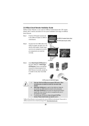
...the other port will remain USB function. 2. Multi-Angle CIR Receiver is used for ASRock motherboard with most of ASRock motherboards. Please install it on ASRock motherboard. Please refer to connect it before you boot the system. * ASRock Smart Remote is only supported by some of the chassis on the market. 3. Please... Remote is only used for front USB only. GND IRTX IRRX ATX+5VSB Install Multi-Angle CIR Receiver to ASRock website for the motherboard support list: http://www.asrock.com 24 Find the CIR header located next to the USB_PWR USB 2.0 header (as below procedures for the...
...the other port will remain USB function. 2. Multi-Angle CIR Receiver is used for ASRock motherboard with most of ASRock motherboards. Please install it on ASRock motherboard. Please refer to connect it before you boot the system. * ASRock Smart Remote is only supported by some of the chassis on the market. 3. Please... Remote is only used for front USB only. GND IRTX IRRX ATX+5VSB Install Multi-Angle CIR Receiver to ASRock website for the motherboard support list: http://www.asrock.com 24 Find the CIR header located next to the USB_PWR USB 2.0 header (as below procedures for the...
User Manual
Page 25
... to 3.0 Gb/s data transfer rate. 25 Please be noted that the password, date, time and user default pro le will cause permanent damage of the motherboard! Placing jumper caps over these 2 pins. However, please do the clear-CMOS action. If you need to clear the CMOS when you just nish updating...
... to 3.0 Gb/s data transfer rate. 25 Please be noted that the password, date, time and user default pro le will cause permanent damage of the motherboard! Placing jumper caps over these 2 pins. However, please do the clear-CMOS action. If you need to clear the CMOS when you just nish updating...

