User Manual
Page 12
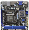
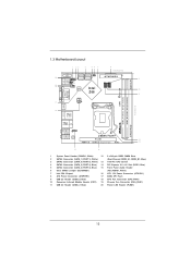
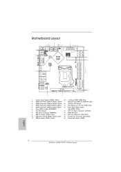
... 2.0 T: USB2 B: USB3 Top: CTR BASS Center: REAR SPK Bottom: Optical SPDIF USB 3.0 T: USB4 Top: B: USB5 RJ-45 HD_AUDIO1 1 Z68M-ITX/HT AUDIO CODEC PCIE1 12 HDMI 1.4a USB 3.0 Designed in Taipei RoHS 13 Top: LINE IN Center: FRONT Bottom: MIC IN 15 14 1 System ... 240-pin DDR3 DIMM Slots 2 SATA3 Connector (SATA_1 (PORT 1), White) (Dual Channel: DDR3_A1, DDR3_B1, Blue) 3 SATA3 Connector (SATA_0 (PORT 0), White) 13 1155-Pin CPU Socket 4 SATA2 Connector (SATA_2 (PORT 4), Blue) 14 PCI Express 2.0 x16 Slot (PCIE1, Blue) 5 SATA2 Connector (SATA_3 (PORT 3), Blue) 15 Front Panel Audio Header...
... 2.0 T: USB2 B: USB3 Top: CTR BASS Center: REAR SPK Bottom: Optical SPDIF USB 3.0 T: USB4 Top: B: USB5 RJ-45 HD_AUDIO1 1 Z68M-ITX/HT AUDIO CODEC PCIE1 12 HDMI 1.4a USB 3.0 Designed in Taipei RoHS 13 Top: LINE IN Center: FRONT Bottom: MIC IN 15 14 1 System ... 240-pin DDR3 DIMM Slots 2 SATA3 Connector (SATA_1 (PORT 1), White) (Dual Channel: DDR3_A1, DDR3_B1, Blue) 3 SATA3 Connector (SATA_0 (PORT 0), White) 13 1155-Pin CPU Socket 4 SATA2 Connector (SATA_2 (PORT 4), Blue) 14 PCI Express 2.0 x16 Slot (PCIE1, Blue) 5 SATA2 Connector (SATA_3 (PORT 3), Blue) 15 Front Panel Audio Header...
User Manual
Page 16
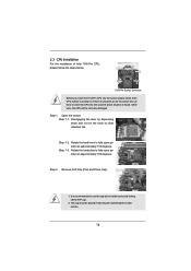
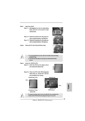
...CPU Installation For the installation of Intel 1155-Pin CPU, please follow the steps below. Step 2. This cap must be seriously damaged. Load Plate Load Lever Contact Array Socket Body 1155-Pin Socket Overview Before you insert the 1155-Pin CPU into the socket if above situation is found. Step... 1. Step 1-2. Step 1-3. Disengaging the lever by depressing down and out on the socket. Do not force to clear ...
...CPU Installation For the installation of Intel 1155-Pin CPU, please follow the steps below. Step 2. This cap must be seriously damaged. Load Plate Load Lever Contact Array Socket Body 1155-Pin Socket Overview Before you insert the 1155-Pin CPU into the socket if above situation is found. Step... 1. Step 1-2. Step 1-3. Disengaging the lever by depressing down and out on the socket. Do not force to clear ...

User Manual
Page 17
Insert the 1155-Pin CPU: Step 3-1. Step 3-4. Verify that the CPU is marked with black line. Rotate the load plate onto the IHS. Carefully place the CPU into the socket by the edge where is within the socket and properly mated to match the two orientation key notches... pressing down lightly on load plate, engage the load lever. 17 orientation key notch alignment key Pin1 Pin1 orientation key notch 1155-Pin CPU alignment key 1155-Pin Socket For proper inserting, please ensure to the orient keys. Step 3. black line Step 3-2. Step 4. Step 3-3. Locate Pin1 and ...
Insert the 1155-Pin CPU: Step 3-1. Step 3-4. Verify that the CPU is marked with black line. Rotate the load plate onto the IHS. Carefully place the CPU into the socket by the edge where is within the socket and properly mated to match the two orientation key notches... pressing down lightly on load plate, engage the load lever. 17 orientation key notch alignment key Pin1 Pin1 orientation key notch 1155-Pin CPU alignment key 1155-Pin Socket For proper inserting, please ensure to the orient keys. Step 3. black line Step 3-2. Step 4. Step 3-3. Locate Pin1 and ...
User Manual
Page 18
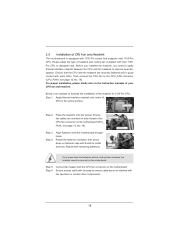
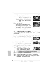
... of CPU Fan and Heatsink This motherboard is an example to illustrate the installation of the heatsink for 1155-Pin CPU. Ensure fan cables are securely fastened and in good contact with 1155-Pin socket that the CPU and the heatsink are oriented on side closest to the instruction manuals of your CPU...
... of CPU Fan and Heatsink This motherboard is an example to illustrate the installation of the heatsink for 1155-Pin CPU. Ensure fan cables are securely fastened and in good contact with 1155-Pin socket that the CPU and the heatsink are oriented on side closest to the instruction manuals of your CPU...
Quick Installation Guide
Page 2
...Top: CTR BASS Center: REAR SPK Bottom: Optical SPDIF USB 3.0 T: USB4 Top: B: USB5 RJ-45 HD_AUDIO1 1 Z68M-ITX/HT AUDIO CODEC PCIE1 12 HDMI 1.4a USB 3.0 Designed in Taipei RoHS 13 Top: LINE IN Center: FRONT Bottom: MIC... 2 SATA3 Connector (SATA_1 (PORT 1), White) (Dual Channel: DDR3_A1, DDR3_B1, Blue) 3 SATA3 Connector (SATA_0 (PORT 0), White) 13 1155-Pin CPU Socket 4 SATA2 Connector (SATA_2 (PORT 4), Blue) 14 PCI Express 2.0 x16 Slot (PCIE1, Blue) 5 SATA2 Connector (SATA_3 (PORT 3), Blue...2.0 Header (USB6_7, Blue) 20 Power LED Header (PLED1) English 2 ASRock Z68M-ITX/HT Motherboard
...Top: CTR BASS Center: REAR SPK Bottom: Optical SPDIF USB 3.0 T: USB4 Top: B: USB5 RJ-45 HD_AUDIO1 1 Z68M-ITX/HT AUDIO CODEC PCIE1 12 HDMI 1.4a USB 3.0 Designed in Taipei RoHS 13 Top: LINE IN Center: FRONT Bottom: MIC... 2 SATA3 Connector (SATA_1 (PORT 1), White) (Dual Channel: DDR3_A1, DDR3_B1, Blue) 3 SATA3 Connector (SATA_0 (PORT 0), White) 13 1155-Pin CPU Socket 4 SATA2 Connector (SATA_2 (PORT 4), Blue) 14 PCI Express 2.0 x16 Slot (PCIE1, Blue) 5 SATA2 Connector (SATA_3 (PORT 3), Blue...2.0 Header (USB6_7, Blue) 20 Power LED Header (PLED1) English 2 ASRock Z68M-ITX/HT Motherboard
Quick Installation Guide
Page 12
...or the like. Load Plate Contact Array Load Lever Socket Body 1155-Pin Socket Overview Before you uninstall any bent pin on a grounded antstatic pad or in the bag that comes with the component. 5. English 12 ASRock Z68M-ITX/HT Motherboard To avoid damaging the motherboard components due to secure... the moth- Also remember to the chassis, please do not over-tighten the screws! Whenever you insert the 1155-Pin CPU into the socket if above situation is any component...
...or the like. Load Plate Contact Array Load Lever Socket Body 1155-Pin Socket Overview Before you uninstall any bent pin on a grounded antstatic pad or in the bag that comes with the component. 5. English 12 ASRock Z68M-ITX/HT Motherboard To avoid damaging the motherboard components due to secure... the moth- Also remember to the chassis, please do not over-tighten the screws! Whenever you insert the 1155-Pin CPU into the socket if above situation is any component...
Quick Installation Guide
Page 13
... the two orientation key notches of the socket. 13 ASRock Z68M-ITX/HT Motherboard English Remove PnP Cap (Pick and Place Cap). 1. black line Step 3-2. Locate Pin1 and the two orientation key notches. orientation key notch alignment key Pin1 Pin1 orientation key notch 1155-Pin CPU alignment key 1155-Pin Socket For proper inserting, please ensure to fully...
... the two orientation key notches of the socket. 13 ASRock Z68M-ITX/HT Motherboard English Remove PnP Cap (Pick and Place Cap). 1. black line Step 3-2. Locate Pin1 and the two orientation key notches. orientation key notch alignment key Pin1 Pin1 orientation key notch 1155-Pin CPU alignment key 1155-Pin Socket For proper inserting, please ensure to fully...
Quick Installation Guide
Page 14
...fastener clockwise, then press down on the motherboard. Fan cables on side closest to illustrate the installation of the heatsink for 1155-Pin CPU. Verify that the CPU is an example to MB header Fastener slots pointing straight out Press Down (4 Places...fastener caps with fan operation or contact other components. Apply Thermal Interface Material Step 2. Step 6. English 14 ASRock Z68M-ITX/HT Motherboard Step 4-3. Carefully place the CPU into the socket by using a purely vertical motion. Step 4. Connect fan header with remaining fasteners. Step 4. Align fasteners...
...fastener clockwise, then press down on the motherboard. Fan cables on side closest to illustrate the installation of the heatsink for 1155-Pin CPU. Verify that the CPU is an example to MB header Fastener slots pointing straight out Press Down (4 Places...fastener caps with fan operation or contact other components. Apply Thermal Interface Material Step 2. Step 6. English 14 ASRock Z68M-ITX/HT Motherboard Step 4-3. Carefully place the CPU into the socket by using a purely vertical motion. Step 4. Connect fan header with remaining fasteners. Step 4. Align fasteners...