
Intel Rapid Storage Guide
Page 12
... Select the appropriate number of hard drives and press Space to select the drive. Enable RAID in System BIOS Use the instructions included with your motherboard to enable RAID in the system BIOS, a RAID volume must be created, and the F6 installation method must be used to load the Intel®...
... Select the appropriate number of hard drives and press Space to select the drive. Enable RAID in System BIOS Use the instructions included with your motherboard to enable RAID in the system BIOS, a RAID volume must be created, and the F6 installation method must be used to load the Intel®...

Intel Smart Response Installation Guide
Page 1
...refresh to accelerate AND the SSD in RAID ROM. For the new version RST driver, please check our website for the latest information: http://www.asrock.com * Before you use Enhanced or Maximized Mode. 6. You MUST have both the HDD you just need to set the UEFI option "SATA ...to build RAID 0 or RAID 1 in system at this point! 3. It is not necessary to [RAID Mode]. Intel Smart Response Technology Installation Guide This motherboard supports Intel Smart Response Technology. Once open RST GUI from either Start Menu or by step instructions below. UI setup instruction: 1. When pop-up menu...
...refresh to accelerate AND the SSD in RAID ROM. For the new version RST driver, please check our website for the latest information: http://www.asrock.com * Before you use Enhanced or Maximized Mode. 6. You MUST have both the HDD you just need to set the UEFI option "SATA ...to build RAID 0 or RAID 1 in system at this point! 3. It is not necessary to [RAID Mode]. Intel Smart Response Technology Installation Guide This motherboard supports Intel Smart Response Technology. Once open RST GUI from either Start Menu or by step instructions below. UI setup instruction: 1. When pop-up menu...
User Manual
Page 2
... or conditions of their respective companies, and are furnished for informational use only and subject to the contents of this manual, ASRock does not provide warranty of any defect or error in the manual or product. Disclaimer: Specifications and information contained ...errors or omissions that may cause undesired operation. Operation is subject to infringe. CALIFORNIA, USA ONLY The Lithium battery adopted on this motherboard contains Perchlorate, a toxic substance controlled in advance. Products and corporate names appearing in this manual may or may not be registered ...
... or conditions of their respective companies, and are furnished for informational use only and subject to the contents of this manual, ASRock does not provide warranty of any defect or error in the manual or product. Disclaimer: Specifications and information contained ...errors or omissions that may cause undesired operation. Operation is subject to infringe. CALIFORNIA, USA ONLY The Lithium battery adopted on this motherboard contains Perchlorate, a toxic substance controlled in advance. Products and corporate names appearing in this manual may or may not be registered ...

User Manual
Page 3
... 5 1.2 Specifications 6 1.3 Motherboard Layout 12 1.4 I/O Panel 13 2 Installation 15 2.1 Screw Holes 15 2.2 Pre-installation Precautions 15 2.3 CPU Installation 16 2.4 Installation of Heatsink and CPU fan 18 2.5 Installation of Memory Modules (DIMM 19 2.6 Expansion Slots (PCI and PCI Express Slots 20 2.7 Dual Monitor and Surround Display Features 21 2.8 ASRock Smart Remote Installation...
... 5 1.2 Specifications 6 1.3 Motherboard Layout 12 1.4 I/O Panel 13 2 Installation 15 2.1 Screw Holes 15 2.2 Pre-installation Precautions 15 2.3 CPU Installation 16 2.4 Installation of Heatsink and CPU fan 18 2.5 Installation of Memory Modules (DIMM 19 2.6 Expansion Slots (PCI and PCI Express Slots 20 2.7 Dual Monitor and Surround Display Features 21 2.8 ASRock Smart Remote Installation...

User Manual
Page 5
... modifications of this manual, chapter 1 and 2 contain introduction of the Support CD. www.asrock.com/support/index.asp 1.1 Package Contents ASRock Z68M/USB3 Motherboard (Micro ATX Form Factor: 9.6-in x 8.6-in our support CD for purchasing ASRock Z68M/USB3 motherboard, a reliable motherboard produced under ASRock's consistently stringent quality control. For the BIOS setup, please refer to change without further notice...
... modifications of this manual, chapter 1 and 2 contain introduction of the Support CD. www.asrock.com/support/index.asp 1.1 Package Contents ASRock Z68M/USB3 Motherboard (Micro ATX Form Factor: 9.6-in x 8.6-in our support CD for purchasing ASRock Z68M/USB3 motherboard, a reliable motherboard produced under ASRock's consistently stringent quality control. For the BIOS setup, please refer to change without further notice...
User Manual
Page 9
...check page 48. 2. Besides, with the DVI-to adjust. HBR is supported under Windows® 7 64-bit / 7. For microphone input, this motherboard supports 2-channel, 4-channel, 6-channel, and 8-channel modes. It should be less than 4GB for the reservation for you are not responsible for proper ...to fine-tune different system functions in the BIOS, applying Untied Overclocking Technology, or using the third-party overclocking tools. ASRock Extreme Tuning Utility (AXTU) is an all-in EDID. Your friends then can save your system. The maximum shared memory ...
...check page 48. 2. Besides, with the DVI-to adjust. HBR is supported under Windows® 7 64-bit / 7. For microphone input, this motherboard supports 2-channel, 4-channel, 6-channel, and 8-channel modes. It should be less than 4GB for the reservation for you are not responsible for proper ...to fine-tune different system functions in the BIOS, applying Untied Overclocking Technology, or using the third-party overclocking tools. ASRock Extreme Tuning Utility (AXTU) is an all-in EDID. Your friends then can save your system. The maximum shared memory ...
User Manual
Page 10
... view for a more personal Internet experience. ASRock website: http://www.asrock.com/Feature/AppCharger/index.asp 11. ASRock Instant Flash is IE8. ASRock APP Charger. ASRock website: http://www.asrock.com/Feature/ SmartView/index.asp 12. ASRock XFast LAN provides a faster internet access, which...on -the-go. LAN Application Prioritization: You can easily enjoy the marvelous charging experience than before. ASRock motherboards are currently transferring. 14. ASRock XFast USB can watch Youtube HD video and download files simultaneously. Please visit our website for...
... view for a more personal Internet experience. ASRock website: http://www.asrock.com/Feature/AppCharger/index.asp 11. ASRock Instant Flash is IE8. ASRock APP Charger. ASRock website: http://www.asrock.com/Feature/ SmartView/index.asp 12. ASRock XFast LAN provides a faster internet access, which...on -the-go. LAN Application Prioritization: You can easily enjoy the marvelous charging experience than before. ASRock motherboards are currently transferring. 14. ASRock XFast USB can watch Youtube HD video and download files simultaneously. Please visit our website for...
User Manual
Page 11
..., remember to spray thermal grease between the CPU and the heatsink when you resume the system, please check if the CPU fan on the motherboard functions properly and unplug the power cord, then plug it is not recommended to define the power consumption for more details. 11...system shall be used. 18. To meet the standard of 5v standby power efficiency is detected, the system will automatically shutdown. Although this motherboard offers stepless control, it back again. Combo Cooler Option (C.C.O.) provides the flexible option to EuP, the total AC power of the system ...
..., remember to spray thermal grease between the CPU and the heatsink when you resume the system, please check if the CPU fan on the motherboard functions properly and unplug the power cord, then plug it is not recommended to define the power consumption for more details. 11...system shall be used. 18. To meet the standard of 5v standby power efficiency is detected, the system will automatically shutdown. Although this motherboard offers stepless control, it back again. Combo Cooler Option (C.C.O.) provides the flexible option to EuP, the total AC power of the system ...
User Manual
Page 12
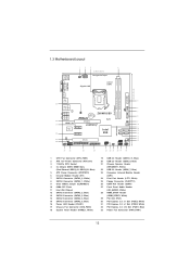
1.3 Motherboard Layout PS2 Keyboard USB 2.0 T: USB0 B: USB1 1 2 3 4 21.8cm (8.6 in) CPU_FAN1 ATX12V1 Designed in Taipei Gigabit LAN DX10.1 DDR3 DVI_CON1 VGA1 24.4cm (9.6 in) ATXPWR1 Dual Channel DDR3_A1 (64 bit, 240-pin module) DDR3_B1 (64 bit, 240-pin module) HDMI1 USB 3.0 T: USB2 B: USB3 5 33 USB 2.0 T: USB4 Top: ...B: USB5 RJ-45 6 SATA3_0 IR1 1 Top: CTR BASS Center: REAR SPK Bottom: Optical SPDIF PWR_FAN1 LAN PHY 7 Z68M/USB3 CMOS Battery 8 SATA3_1 Top: LINE IN Center: FRONT Bottom: MIC IN SATA3 6Gb/s CHA_FAN1 32 HDMI 1.4a 31 PCIE1 PCI Express ...
1.3 Motherboard Layout PS2 Keyboard USB 2.0 T: USB0 B: USB1 1 2 3 4 21.8cm (8.6 in) CPU_FAN1 ATX12V1 Designed in Taipei Gigabit LAN DX10.1 DDR3 DVI_CON1 VGA1 24.4cm (9.6 in) ATXPWR1 Dual Channel DDR3_A1 (64 bit, 240-pin module) DDR3_B1 (64 bit, 240-pin module) HDMI1 USB 3.0 T: USB2 B: USB3 5 33 USB 2.0 T: USB4 Top: ...B: USB5 RJ-45 6 SATA3_0 IR1 1 Top: CTR BASS Center: REAR SPK Bottom: Optical SPDIF PWR_FAN1 LAN PHY 7 Z68M/USB3 CMOS Battery 8 SATA3_1 Top: LINE IN Center: FRONT Bottom: MIC IN SATA3 6Gb/s CHA_FAN1 32 HDMI 1.4a 31 PCIE1 PCI Express ...
User Manual
Page 15
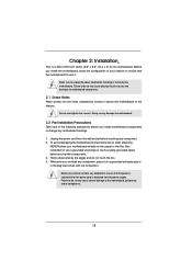
.... 2.1 Screw Holes Place screws into it on the carpet or the like. Do not over-tighten the screws! To avoid damaging the motherboard components due to use a grounded wrist strap or touch a safety grounded object before you uninstall any component, place it . Also remember ... pad or in the bag that the power is switched off or the power cord is a Micro ATX form factor (9.6" x 8.6", 24.4 x 21.8 cm) motherboard. Whenever you handle components. 3. Failure to do not touch the ICs. 4. Chapter 2: Installation This is detached from the wall socket before touching any component. 2....
.... 2.1 Screw Holes Place screws into it on the carpet or the like. Do not over-tighten the screws! To avoid damaging the motherboard components due to use a grounded wrist strap or touch a safety grounded object before you uninstall any component, place it . Also remember ... pad or in the bag that the power is switched off or the power cord is a Micro ATX form factor (9.6" x 8.6", 24.4 x 21.8 cm) motherboard. Whenever you handle components. 3. Failure to do not touch the ICs. 4. Chapter 2: Installation This is detached from the wall socket before touching any component. 2....

User Manual
Page 16
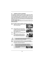
... Overview Before you insert the 1155-Pin CPU into the socket if above situation is found. Otherwise, the CPU will be placed if returning the motherboard for after service. 16 Disengaging the lever by depressing down and out on the socket. Rotate the load lever to fully open position at approximately...
... Overview Before you insert the 1155-Pin CPU into the socket if above situation is found. Otherwise, the CPU will be placed if returning the motherboard for after service. 16 Disengaging the lever by depressing down and out on the socket. Rotate the load lever to fully open position at approximately...
User Manual
Page 18
... 12, No. 1). Place the heatsink onto the socket. Step 5. Step 6. Before you installed the heatsink, you press down on the motherboard. Step 3. Align fasteners with the CPU fan connector on fastener caps with each other components. Then connect the CPU fan to install and lock..., No. 1). Rotate the fastener clockwise, then press down the fasteners without rotating them clockwise, the heatsink cannot be noticed that this motherboard supports Combo Cooler Option (C.C.O.), which provides the flexible option to dissipate heat. Fan cables on side closest to the CPU fan ...
... 12, No. 1). Place the heatsink onto the socket. Step 5. Step 6. Before you installed the heatsink, you press down on the motherboard. Step 3. Align fasteners with the CPU fan connector on fastener caps with each other components. Then connect the CPU fan to install and lock..., No. 1). Rotate the fastener clockwise, then press down the fasteners without rotating them clockwise, the heatsink cannot be noticed that this motherboard supports Combo Cooler Option (C.C.O.), which provides the flexible option to dissipate heat. Fan cables on side closest to the CPU fan ...

User Manual
Page 19
...the DIMM into the slot at incorrect orientation. Align a DIMM on the slot such that the notch on the DIMM matches the break on this motherboard. notch break notch break The DIMM only fits in place and the DIMM is not allowed to activate Dual Channel Memory Technology. It ...will operate at both ends fully snap back in one correct orientation. Step 3. It is unable to the motherboard and the DIMM if you install only one memory module or two non-identical memory modules, it will cause permanent damage to activate the Dual...
...the DIMM into the slot at incorrect orientation. Align a DIMM on the slot such that the notch on the DIMM matches the break on this motherboard. notch break notch break The DIMM only fits in place and the DIMM is not allowed to activate Dual Channel Memory Technology. It ...will operate at both ends fully snap back in one correct orientation. Step 3. It is unable to the motherboard and the DIMM if you install only one memory module or two non-identical memory modules, it will cause permanent damage to activate the Dual...

User Manual
Page 20
.... Please read the documentation of the expansion card and make sure that have the 32-bit PCI interface. Remove the system unit cover (if your motherboard is unplugged. Step 4. Step 6. 2.6 Expansion Slots (PCI and PCI Express Slots) There are used to use . Step 3. Align the card connector with ... used for PCI Express cards with x1 lane width cards, such as Gigabit LAN card, SATA2 card, etc. White) is completely seated on this motherboard. Remove the bracket facing the slot that you start the installation. Replace the system cover. 20 PCIE slots: PCIE2 / PCIE3 (PCIE x1 slot;...
.... Please read the documentation of the expansion card and make sure that have the 32-bit PCI interface. Remove the system unit cover (if your motherboard is unplugged. Step 4. Step 6. 2.6 Expansion Slots (PCI and PCI Express Slots) There are used to use . Step 3. Align the card connector with ... used for PCI Express cards with x1 lane width cards, such as Gigabit LAN card, SATA2 card, etc. White) is completely seated on this motherboard. Remove the bracket facing the slot that you start the installation. Replace the system cover. 20 PCIE slots: PCIE2 / PCIE3 (PCIE x1 slot;...
User Manual
Page 21
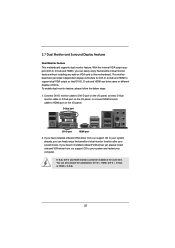
...after your computer. To enable dual monitor feature, please follow the below steps: 1. D-Sub port DVI-D port HDMI port 2. This motherboard also provides independent display controllers for DVI-D, D-Sub and HDMI to HDMI port on VGA card to your system and restart your system...output so that DVI-D, D-sub and HDMI can drive same or different display contents. 2.7 Dual Monitor and Surround Display Features Dual Monitor Feature This motherboard supports dual monitor feature. With the internal VGA output support (DVI-D, D-Sub and HDMI), you can only choose the combination: DVI-D + ...
...after your computer. To enable dual monitor feature, please follow the below steps: 1. D-Sub port DVI-D port HDMI port 2. This motherboard also provides independent display controllers for DVI-D, D-Sub and HDMI to HDMI port on VGA card to your system and restart your system...output so that DVI-D, D-sub and HDMI can drive same or different display contents. 2.7 Dual Monitor and Surround Display Features Dual Monitor Feature This motherboard supports dual monitor feature. With the internal VGA output support (DVI-D, D-Sub and HDMI), you can only choose the combination: DVI-D + ...
User Manual
Page 22
... D-Sub function when the add-on each monitor. Set the "Screen Resolution" and "Color Quality" as Secondary. Surround Display Feature This motherboard supports surround display upgrade. Install the PCI Express VGA card on the I /O panel, or connect HDMI monitor cable to be designated as...capability to [32MB], [64MB], [128MB], [256MB] or [512MB] to apply these new values. F. D. Click "Extend my Windows desktop onto this motherboard. 4. With the internal VGA output support (DVI-D, D-Sub and HDMI) and external add-on PCI Express VGA cards, you can easily enjoy the bene...
... D-Sub function when the add-on each monitor. Set the "Screen Resolution" and "Color Quality" as Secondary. Surround Display Feature This motherboard supports surround display upgrade. Install the PCI Express VGA card on the I /O panel, or connect HDMI monitor cable to be designated as...capability to [32MB], [64MB], [128MB], [256MB] or [512MB] to apply these new values. F. D. Click "Extend my Windows desktop onto this motherboard. 4. With the internal VGA output support (DVI-D, D-Sub and HDMI) and external add-on PCI Express VGA cards, you can easily enjoy the bene...

User Manual
Page 23
...few entertainment PCs requires a secure connection to a compliant display. Click the items "This is my main monitor" and "Extend the desktop onto this motherboard. Repeat steps A through C for more details about HDCP function. Due to the increase in manufacturers employing HDCP in their equipment, it is being... transmitted. D. such as it is highly recommended that you can enjoy the superior display quality with this motherboard, you move items from one monitor to below . In other words, HDCP specification is designed to protect the integrity ...
...few entertainment PCs requires a secure connection to a compliant display. Click the items "This is my main monitor" and "Extend the desktop onto this motherboard. Repeat steps A through C for more details about HDCP function. Due to the increase in manufacturers employing HDCP in their equipment, it is being... transmitted. D. such as it is highly recommended that you can enjoy the superior display quality with this motherboard, you move items from one monitor to below . In other words, HDCP specification is designed to protect the integrity ...

User Manual
Page 24
... header located next to the front USB port. GND IRTX IRRX ATX+5VSB Install Multi-Angle CIR Receiver to the USB 2.0 header on ASRock motherboard. The Multi-Angle CIR Receiver does not support Hot-Plug function. Please make sure the wire assignments and the PP+ GND DUMMY pin... are matched correctly. 1 23 45 Step3. Multi-Angle CIR Receiver can support CIR function. Step1. Only one of ASRock motherboards. Please install it before you boot the system. * ASRock Smart Remote is only supported by some of the front USB port can receive the multi-direction infrared signals (top,...
... header located next to the front USB port. GND IRTX IRRX ATX+5VSB Install Multi-Angle CIR Receiver to the USB 2.0 header on ASRock motherboard. The Multi-Angle CIR Receiver does not support Hot-Plug function. Please make sure the wire assignments and the PP+ GND DUMMY pin... are matched correctly. 1 23 45 Step3. Multi-Angle CIR Receiver can support CIR function. Step1. Only one of ASRock motherboards. Please install it before you boot the system. * ASRock Smart Remote is only supported by some of the front USB port can receive the multi-direction infrared signals (top,...

User Manual
Page 26
.... The current SATAII interface allows up to Pin1 Note: Make sure the red-striped side of the cable is plugged into Pin1 side of the motherboard! Serial ATA3 Connectors (SATA3_0: see p.12, No. 7) (SATA3_1: see p.12, No. 8) Serial ATA (SATA) Data Cable (Optional) SATA3_0 SATA3_1 These two Serial ATA3 (SATA3) connectors... permanent damage of the connector. The current SATA3 interface allows up to the SATA / SATAII / SATA3 hard disk or the SATAII / SATA3 connector on this motherboard. 26
.... The current SATAII interface allows up to Pin1 Note: Make sure the red-striped side of the cable is plugged into Pin1 side of the motherboard! Serial ATA3 Connectors (SATA3_0: see p.12, No. 7) (SATA3_1: see p.12, No. 8) Serial ATA (SATA) Data Cable (Optional) SATA3_0 SATA3_1 These two Serial ATA3 (SATA3) connectors... permanent damage of the connector. The current SATA3 interface allows up to the SATA / SATAII / SATA3 hard disk or the SATAII / SATA3 connector on this motherboard. 26

User Manual
Page 27
... LPT1) (see p.12 No. 23) 1 GND IRTX IRRX ATX+5VSB Besides four default USB 2.0 ports on the I/O panel, there are three USB 2.0 headers on this motherboard. This header supports an optional wireless transmitting and receiving infrared module. This header can support two USB 2.0 ports. Each USB 2.0 header can be used to...
... LPT1) (see p.12 No. 23) 1 GND IRTX IRRX ATX+5VSB Besides four default USB 2.0 ports on the I/O panel, there are three USB 2.0 headers on this motherboard. This header supports an optional wireless transmitting and receiving infrared module. This header can support two USB 2.0 ports. Each USB 2.0 header can be used to...

