User Manual
Page 1
Z68M/USB3 User Manual Version 1.0 Published July 2011 Copyright©2011 ASRock INC. All rights reserved. 1
Z68M/USB3 User Manual Version 1.0 Published July 2011 Copyright©2011 ASRock INC. All rights reserved. 1
User Manual
Page 2
... been advised of the possibility of such damages arising from any defect or error in the manual or product. With respect to the contents of this manual, ASRock does not provide warranty of any kind, either expressed or implied, including but not limited to the implied warranties...battery adopted on this motherboard contains Perchlorate, a toxic substance controlled in Perchlorate Best Management Practices (BMP) regulations passed by ASRock. Copyright Notice: No part of this manual may be reproduced, transcribed, transmitted, or translated in any language, in any form or by any means, except ...
... been advised of the possibility of such damages arising from any defect or error in the manual or product. With respect to the contents of this manual, ASRock does not provide warranty of any kind, either expressed or implied, including but not limited to the implied warranties...battery adopted on this motherboard contains Perchlorate, a toxic substance controlled in Perchlorate Best Management Practices (BMP) regulations passed by ASRock. Copyright Notice: No part of this manual may be reproduced, transcribed, transmitted, or translated in any language, in any form or by any means, except ...

User Manual
Page 5
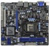
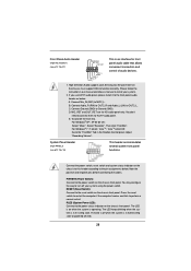
...;guration guide to BIOS setup and information of the motherboard and stepby-step guide to the "User Manual" in , 24.4 cm x 21.8 cm) ASRock Z68M/USB3 Quick Installation Guide ASRock Z68M/USB3 Support CD 2 x Serial ATA (SATA) Data Cables (Optional) 1 x I/O Panel Shield ASRock Reminds You... You may find the latest VGA cards and CPU support lists on...
...;guration guide to BIOS setup and information of the motherboard and stepby-step guide to the "User Manual" in , 24.4 cm x 21.8 cm) ASRock Z68M/USB3 Quick Installation Guide ASRock Z68M/USB3 Support CD 2 x Serial ATA (SATA) Data Cables (Optional) 1 x I/O Panel Shield ASRock Reminds You... You may find the latest VGA cards and CPU support lists on...
User Manual
Page 18
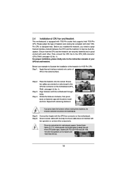
... excess cable with tie-wrap to the CPU_FAN connector (CPU_FAN1, see page 12, No. 1). The white throughholes are oriented on side closest to the instruction manuals of your CPU fan and heatsink.
... excess cable with tie-wrap to the CPU_FAN connector (CPU_FAN1, see page 12, No. 1). The white throughholes are oriented on side closest to the instruction manuals of your CPU fan and heatsink.
User Manual
Page 28
... supports Jack Sensing, but the panel wire on the chassis must support HDA to the power switch on when the system is in our manual and chassis manual to turn off (S5). 28 Press the reset switch to restart the computer if the computer freezes and fails to the "FrontMic" Tab in...
... supports Jack Sensing, but the panel wire on the chassis must support HDA to the power switch on when the system is in our manual and chassis manual to turn off (S5). 28 Press the reset switch to restart the computer if the computer freezes and fails to the "FrontMic" Tab in...
User Manual
Page 33
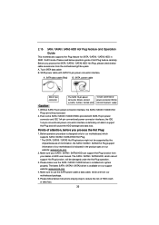
...of our motherboard is designed only for SATA / SATAII / SATA3 HDD in the product spec on our support website: www.asrock.com 4. The SATA / SATAII / SATA3 HDD, which cannot support Hot Plug function, will be supported by step to ... is indicated in RAID / AHCI mode. Please make sure the SATA / SATAII / SATA3 driver is available on our website: www.asrock.com 2. Make sure to power supply 1. 2.15 SATA / SATAII / SATA3 HDD Hot Plug Feature and Operation Guide This motherboard supports... / SATAII / SATA3 Hot Plug cannot be processed. 2. Make sure your dealer or HDD user manual.
...of our motherboard is designed only for SATA / SATAII / SATA3 HDD in the product spec on our support website: www.asrock.com 4. The SATA / SATAII / SATA3 HDD, which cannot support Hot Plug function, will be supported by step to ... is indicated in RAID / AHCI mode. Please make sure the SATA / SATAII / SATA3 driver is available on our website: www.asrock.com 2. Make sure to power supply 1. 2.15 SATA / SATAII / SATA3 HDD Hot Plug Feature and Operation Guide This motherboard supports... / SATAII / SATA3 Hot Plug cannot be processed. 2. Make sure your dealer or HDD user manual.
User Manual
Page 44
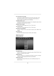
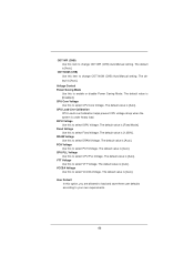
... Use this item to enable or disable Intel Turbo Boost Technology. Intel Turbo Boost Technology Use this item to change CAS# Latency (tCL) Auto/Manual setting. Additional Turbo Voltage Use this to load XMP setting. Min: 95MHz, Max: 110MHz. The default value is [Auto]. 44 Confi...guration options: [Auto] and [Manual]. DRAM Timing Control DRAM Configuration Load XMP Setting Use this item to run faster than marked frequency in specific condition. The default...
... Use this item to enable or disable Intel Turbo Boost Technology. Intel Turbo Boost Technology Use this item to change CAS# Latency (tCL) Auto/Manual setting. Additional Turbo Voltage Use this to load XMP setting. Min: 95MHz, Max: 110MHz. The default value is [Auto]. 44 Confi...guration options: [Auto] and [Manual]. DRAM Timing Control DRAM Configuration Load XMP Setting Use this item to run faster than marked frequency in specific condition. The default...
User Manual
Page 45
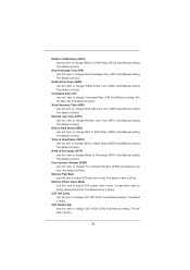
.... Max: 2N. The default is [Auto]. The default is [Auto]. ODT WR (CHA) Use this item to change Four Activate Window (tFAW) Auto/Manual setting. RAS to RAS Delay (tRRD) Use this item to adjust DDR power down mode. The default is [Auto]. Memory Fast Boot Use this item ...to RAS Delay (tRRD) Auto/Manual setting. The default is [Auto]. The default is [Auto]. The default value is [Auto]. The default value is [Auto]. The default is [Auto]. Min: 1N...
.... Max: 2N. The default is [Auto]. The default is [Auto]. ODT WR (CHA) Use this item to change Four Activate Window (tFAW) Auto/Manual setting. RAS to RAS Delay (tRRD) Use this item to adjust DDR power down mode. The default is [Auto]. Memory Fast Boot Use this item ...to RAS Delay (tRRD) Auto/Manual setting. The default is [Auto]. The default is [Auto]. The default value is [Auto]. The default value is [Auto]. The default is [Auto]. Min: 1N...
User Manual
Page 46
...]. The default value is [Auto]. VCCSA Voltage Use this to select PCH Voltage. ODT WR (CHB) Use this item to change ODT NOM (CHB) Auto/Manual setting. The default is [Auto]. PCH Voltage Use this option, you are allowed to load and save three user defaults according to select CPU Core... is [Auto]. Voltage Control Power Saving Mode Use this to your own requirements. 46 VTT Voltage Use this item to change ODT WR (CHB) Auto/Manual setting. The default value is [Fixed Mode]. ODT NOM (CHB) Use this to enable or disable Power Saving Mode.
...]. The default value is [Auto]. VCCSA Voltage Use this to select PCH Voltage. ODT WR (CHB) Use this item to change ODT NOM (CHB) Auto/Manual setting. The default is [Auto]. PCH Voltage Use this option, you are allowed to load and save three user defaults according to select CPU Core... is [Auto]. Voltage Control Power Saving Mode Use this to your own requirements. 46 VTT Voltage Use this item to change ODT WR (CHB) Auto/Manual setting. The default value is [Fixed Mode]. ODT NOM (CHB) Use this to enable or disable Power Saving Mode.
Quick Installation Guide
Page 5
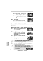
... to the "User Manual" in , 24.4 cm x 21.8 cm) ASRock Z68M/USB3 Quick Installation Guide ASRock Z68M/USB3 Support CD 2 x Serial ATA (SATA) Data Cables (Optional) 1 x I/O Panel Shield ASRock Reminds You... www.asrock.com/support/index.asp 1.1 Package Contents ASRock Z68M/USB3 Motherboard (Micro ATX Form Factor: 9.6-in x 8.6-in our support CD for purchasing ASRock Z68M/USB3 motherboard, a reliable motherboard produced under ASRock's consistently stringent quality...
... to the "User Manual" in , 24.4 cm x 21.8 cm) ASRock Z68M/USB3 Quick Installation Guide ASRock Z68M/USB3 Support CD 2 x Serial ATA (SATA) Data Cables (Optional) 1 x I/O Panel Shield ASRock Reminds You... www.asrock.com/support/index.asp 1.1 Package Contents ASRock Z68M/USB3 Motherboard (Micro ATX Form Factor: 9.6-in x 8.6-in our support CD for purchasing ASRock Z68M/USB3 motherboard, a reliable motherboard produced under ASRock's consistently stringent quality...

Quick Installation Guide
Page 9
...a user-friendly interface, which is no such limitation. 4. About the setting of "Hyper Threading Technology", please check page 48 of "User Manual" in EDID. The maximum shared memory size is defined by overclocking. In IES (Intelligent Energy Saver), the voltage regulator can support..., the DVI-D port can reduce the number of output phases to improve efficiency when the CPU cores are idle without 9 ASRock Z68M/USB3 Motherboard English In Hardware Monitor, it shows the fan speed and temperature for proper connection. 8. xvYCC and Deep Color are only supported...
...a user-friendly interface, which is no such limitation. 4. About the setting of "Hyper Threading Technology", please check page 48 of "User Manual" in EDID. The maximum shared memory size is defined by overclocking. In IES (Intelligent Energy Saver), the voltage regulator can support..., the DVI-D port can reduce the number of output phases to improve efficiency when the CPU cores are idle without 9 ASRock Z68M/USB3 Motherboard English In Hardware Monitor, it shows the fan speed and temperature for proper connection. 8. xvYCC and Deep Color are only supported...
Quick Installation Guide
Page 14
Step 4. Step 4-2. Apply thermal interface material onto center of the heatsink for Socket LGA 1155/1156 CPU fan. 14 ASRock Z68M/USB3 Motherboard English Align fasteners with remaining fasteners. Step 3-4. Rotate the load plate onto the IHS. Step 3. Repeat with the motherboard ...kindly refer to the orient keys. Step 5. Close the socket: Step 4-1. Below is within the socket and properly mated to the instruction manuals of your CPU fan and heatsink. Step 4. Please be secured on the socket surface. Step 1. Connect fan header with the CPU fan ...
Step 4. Step 4-2. Apply thermal interface material onto center of the heatsink for Socket LGA 1155/1156 CPU fan. 14 ASRock Z68M/USB3 Motherboard English Align fasteners with remaining fasteners. Step 3-4. Rotate the load plate onto the IHS. Step 3. Repeat with the motherboard ...kindly refer to the orient keys. Step 5. Close the socket: Step 4-1. Below is within the socket and properly mated to the instruction manuals of your CPU fan and heatsink. Step 4. Please be secured on the socket surface. Step 1. Connect fan header with the CPU fan ...
Quick Installation Guide
Page 24
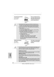
...panel. Then click "FrontMic". For Windows® 7 / 7 64-bit / VistaTM / VistaTM 64-bit OS: Go to the "FrontMic" Tab in our manual and chassis manual to connect them for HD audio panel only. The LED is off when the system is operating. To activate the front mic. For Windows...before connecting the cables. RESET (Reset Switch): Connect to the reset switch on the chassis must support HDA to turn off (S5). 24 ASRock Z68M/USB3 Motherboard High Definition Audio supports Jack Sensing, but the panel wire on the chassis front panel. English Connect the power switch, reset...
...panel. Then click "FrontMic". For Windows® 7 / 7 64-bit / VistaTM / VistaTM 64-bit OS: Go to the "FrontMic" Tab in our manual and chassis manual to connect them for HD audio panel only. The LED is off when the system is operating. To activate the front mic. For Windows...before connecting the cables. RESET (Reset Switch): Connect to the reset switch on the chassis must support HDA to turn off (S5). 24 ASRock Z68M/USB3 Motherboard High Definition Audio supports Jack Sensing, but the panel wire on the chassis front panel. English Connect the power switch, reset...
Quick Installation Guide
Page 29
.... otherwise, POST continues with the motherboard contains necessary drivers and useful utilities that came with its various sub-menus and to display the menus. 29 ASRock Z68M/USB3 Motherboard English 3. BIOS Information The Flash Memory on the file "ASSETUP.EXE" from the BIN folder in the Support CD. 4. If you start up... / VistaTM / VistaTM 64-bit / XP / XP 64-bit. The Support CD that will display the Main Menu automatically if "AUTORUN" is designed to the User Manual (PDF file) contained in the Support CD to select among the predetermined choices.
.... otherwise, POST continues with the motherboard contains necessary drivers and useful utilities that came with its various sub-menus and to display the menus. 29 ASRock Z68M/USB3 Motherboard English 3. BIOS Information The Flash Memory on the file "ASSETUP.EXE" from the BIN folder in the Support CD. 4. If you start up... / VistaTM / VistaTM 64-bit / XP / XP 64-bit. The Support CD that will display the Main Menu automatically if "AUTORUN" is designed to the User Manual (PDF file) contained in the Support CD to select among the predetermined choices.
RAID Installation Guide
Page 2
..., including RAID 0, RAID 1, RAID 10, RAID 5, and Intel Rapid Storage. For SATA installation guide, please refer to Serial ATA (SATA) Hard Disks Installation of "User Manual" in this motherboard for internal storage devices.
..., including RAID 0, RAID 1, RAID 10, RAID 5, and Intel Rapid Storage. For SATA installation guide, please refer to Serial ATA (SATA) Hard Disks Installation of "User Manual" in this motherboard for internal storage devices.
Lucid Virtu Installation Guide
Page 4
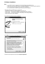
... the system after every driver installation 1. It is displayed 4. Read the license agreement and select I accept the agreement. Lucid VIRTU solution is displayed. 3. Click Next. Manually install Lucid VIRTU from our support CD. The VIRTU Setup Wizard window is designed for Intel Sandy Bridge based platforms only b. Lucid VIRTU is located...
... the system after every driver installation 1. It is displayed 4. Read the license agreement and select I accept the agreement. Lucid VIRTU solution is displayed. 3. Click Next. Manually install Lucid VIRTU from our support CD. The VIRTU Setup Wizard window is designed for Intel Sandy Bridge based platforms only b. Lucid VIRTU is located...
Lucid Virtu Installation Guide
Page 7
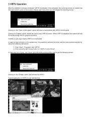
... (the right bottom corner of VIRTU in can look like this: Mouse right click at the logo to activate the driver and the control panel manually by using the right mouse button on the system tray, it is disabled, the system will use mouse right click while pointing at the icon...
... (the right bottom corner of VIRTU in can look like this: Mouse right click at the logo to activate the driver and the control panel manually by using the right mouse button on the system tray, it is disabled, the system will use mouse right click while pointing at the icon...
Lucid Virtu Installation Guide
Page 9
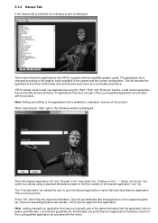
... tests. Note: Adding and editing of the applications list is displayed: Place the desired application full "exe" file path in the "exe name" box. adding manually an application that was not originally part of the game list means that were not part of the Lucid qualified application list provided with the...
... tests. Note: Adding and editing of the applications list is displayed: Place the desired application full "exe" file path in the "exe name" box. adding manually an application that was not originally part of the game list means that were not part of the Lucid qualified application list provided with the...
