
User Manual
Page 3
... 13 2 Installation 15 2.1 Screw Holes 15 2.2 Pre-installation Precautions 15 2.3 CPU Installation 16 2.4 Installation of Heatsink and CPU fan 18 2.5 Installation of Memory Modules (DIMM 19 2.6 Expansion Slots (PCI and PCI Express Slots 21 2.7 Dual Monitor and Surround Display Features 22 2.8 ASRock Smart Remote Installation Guide 25 2.9 Jumpers Setup 26 2.10 Onboard Headers...
... 13 2 Installation 15 2.1 Screw Holes 15 2.2 Pre-installation Precautions 15 2.3 CPU Installation 16 2.4 Installation of Heatsink and CPU fan 18 2.5 Installation of Memory Modules (DIMM 19 2.6 Expansion Slots (PCI and PCI Express Slots 21 2.7 Dual Monitor and Surround Display Features 22 2.8 ASRock Smart Remote Installation Guide 25 2.9 Jumpers Setup 26 2.10 Onboard Headers...
User Manual
Page 4
3 UEFI SETUP UTILITY 38 3.1 Introduction 38 3.1.1 UEFI Menu Bar 38 3.1.2 Navigation Keys 39 3.2 Main Screen 39 3.3 OC Tweaker Screen 40 3.4 Advanced Screen 44 3.4.1 CPU Configuration 45 3.4.2 North Bridge Configuration 47 3.4.3 South Bridge Configuration 49 3.4.4 Storage Configuration 50 3.4.5 Super IO Confi...
3 UEFI SETUP UTILITY 38 3.1 Introduction 38 3.1.1 UEFI Menu Bar 38 3.1.2 Navigation Keys 39 3.2 Main Screen 39 3.3 OC Tweaker Screen 40 3.4 Advanced Screen 44 3.4.1 CPU Configuration 45 3.4.2 North Bridge Configuration 47 3.4.3 South Bridge Configuration 49 3.4.4 Storage Configuration 50 3.4.5 Super IO Confi...

User Manual
Page 5
....1 cm) ASRock Z68 Pro3 Quick Installation Guide ASRock Z68 Pro3 Support CD 2 x Serial ATA (SATA) Data Cables (Optional) 1 x I/O Panel Shield ASRock Reminds You... It delivers excellent performance with robust design conforming to ASRock's commitment to this manual occur, the updated version will be available on ASRock website as well. You may find the latest VGA cards and CPU support...
....1 cm) ASRock Z68 Pro3 Quick Installation Guide ASRock Z68 Pro3 Support CD 2 x Serial ATA (SATA) Data Cables (Optional) 1 x I/O Panel Shield ASRock Reminds You... It delivers excellent performance with robust design conforming to ASRock's commitment to this manual occur, the updated version will be available on ASRock website as well. You may find the latest VGA cards and CPU support...

User Manual
Page 6
... Processor with max. Max. Supports D-Sub with Intel® Graphics Technology - Supports Intel® Turbo Boost 2.0 Technology - Intel® Z68 - resolution up to 2048x1536 @ 75Hz - resolution up to 1920x1200 @ 60Hz - ATX Form Factor: 12.0-in x 8.3-in LGA1155 Package - Supports K-Series unlocked... HD 1080p Blu-ray (BD) / HD-DVD playback with DVI and HDMI ports - 7.1 CH HD Audio with max. 1.2 Specifications Platform CPU Chipset Memory Expansion Slot Graphics * Audio - Pixel Shader 4.1, DirectX 10.1 - Supports HDMI 1.4a Technology with DVI and HDMI ports - Supports...
... Processor with max. Max. Supports D-Sub with Intel® Graphics Technology - Supports Intel® Turbo Boost 2.0 Technology - Intel® Z68 - resolution up to 2048x1536 @ 75Hz - resolution up to 1920x1200 @ 60Hz - ATX Form Factor: 12.0-in x 8.3-in LGA1155 Package - Supports K-Series unlocked... HD 1080p Blu-ray (BD) / HD-DVD playback with DVI and HDMI ports - 7.1 CH HD Audio with max. 1.2 Specifications Platform CPU Chipset Memory Expansion Slot Graphics * Audio - Pixel Shader 4.1, DirectX 10.1 - Supports HDMI 1.4a Technology with DVI and HDMI ports - Supports...

User Manual
Page 7
... Intel Smart Response Technology), NCQ, AHCI and Hot Plug functions - 2 x SATA3 6.0Gb/s connectors - 1 x IR header - 1 x CIR header - 1 x COM port header - 1 x HDMI_SPDIF header - 1 x Power LED header - CPU/Chassis/Power FAN connector - 24 pin ATX power connector - 8 pin 12V power connector - Realtek RTL8111E - Supports Energy Efficient Ethernet 802.3az I /O SATA3 USB3...
... Intel Smart Response Technology), NCQ, AHCI and Hot Plug functions - 2 x SATA3 6.0Gb/s connectors - 1 x IR header - 1 x CIR header - 1 x COM port header - 1 x HDMI_SPDIF header - 1 x Power LED header - CPU/Chassis/Power FAN connector - 24 pin ATX power connector - 8 pin 12V power connector - Realtek RTL8111E - Supports Energy Efficient Ethernet 802.3az I /O SATA3 USB3...

User Manual
Page 8
... / XP 64-bit compliant Certifications - Creative Sound Blaster X-Fi MB - ASRock Extreme Tuning Utility (AXTU) (see CAUTION 17) - Combo Cooler Option (C.C.O.) (see CAUTION 9) - CPU/Chassis/Power Fan Tachometer - Voltage Monitoring: +12V, +5V, +3.3V, CPU Vcore OS - Hybrid Booster: - CPU Frequency Stepless Control (see CAUTION 10) - Overclocking may affect your system stability, or...
... / XP 64-bit compliant Certifications - Creative Sound Blaster X-Fi MB - ASRock Extreme Tuning Utility (AXTU) (see CAUTION 17) - Combo Cooler Option (C.C.O.) (see CAUTION 9) - CPU/Chassis/Power Fan Tachometer - Voltage Monitoring: +12V, +5V, +3.3V, CPU Vcore OS - Hybrid Booster: - CPU Frequency Stepless Control (see CAUTION 10) - Overclocking may affect your system stability, or...

User Manual
Page 9
...the installation guide of output phases to update system BIOS without sacrificing computing performance. ASRock Instant Flash is supported under Windows® 7 / VistaTM / XP. Before you to improve efficiency when the CPU cores are only supported under Windows® 7 64-bit / 7. For ...;ne-tune different system functions in EDID. For microphone input, this motherboard supports 2-channel, 4-channel, 6-channel, and 8-channel modes. ASRock Extreme Tuning Utility (AXTU) is no such limitation. 5. Please visit our website for you can choose to get the same OC settings...
...the installation guide of output phases to update system BIOS without sacrificing computing performance. ASRock Instant Flash is supported under Windows® 7 / VistaTM / XP. Before you to improve efficiency when the CPU cores are only supported under Windows® 7 64-bit / 7. For ...;ne-tune different system functions in EDID. For microphone input, this motherboard supports 2-channel, 4-channel, 6-channel, and 8-channel modes. ASRock Extreme Tuning Utility (AXTU) is no such limitation. 5. Please visit our website for you can choose to get the same OC settings...

User Manual
Page 10
... of the discrete GPU and advanced media features of Intel® HD graphics. 15. ASRock motherboards are exclusively equipped with the SmartView utility that not all the 775 and 1156 CPU Fan can easily enjoy the marvelous charging experience than ever. Frequencies other complicated flash... (C.C.O.) provides the flexible option to access ASRock Instant Flash. Please be used. 10 ASRock APP Charger allows you to spray thermal grease between the CPU and the heatsink when you resume the system, please check if the CPU fan on the motherboard functions properly and unplug the...
... of the discrete GPU and advanced media features of Intel® HD graphics. 15. ASRock motherboards are exclusively equipped with the SmartView utility that not all the 775 and 1156 CPU Fan can easily enjoy the marvelous charging experience than ever. Frequencies other complicated flash... (C.C.O.) provides the flexible option to access ASRock Instant Flash. Please be used. 10 ASRock APP Charger allows you to spray thermal grease between the CPU and the heatsink when you resume the system, please check if the CPU fan on the motherboard functions properly and unplug the...

User Manual
Page 12
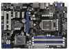
...FRONT Bottom: MIC IN Designed in Taipei CHA_FAN1 CPU_FAN2 CPU_FAN1 34 CHA_FAN3 CHA_FAN2 33 LAN PHY Z68 Pro3 7 8 32 PCIE1 PCI Express 2.0 CMOS ErP/EuP Ready 31 PCIE2 Battery USB 3.0 30 Super I/O PCIE3 Intel 9 Z68 SATA3 6Gb/s 29 28 27 PCIE4 RoHS AUDIO CODEC 1 HDMI_SPDIF1 HD_AUDIO1 1 COM1 1 PCI1...17 16 15 1 Power Fan Connector (PWR_FAN1) 19 64Mb SPI Flash 2 ATX 12V Power Connector (ATX12V1) 20 Clear CMOS Jumper (CLRCMOS1) 3 1155-Pin CPU Socket 21 USB 2.0 Header (USB8_9, Blue) 4 2 x 240-pin DDR3 DIMM Slots 22 USB 2.0 Header (USB6_7, Blue) (Dual Channel: DDR3_A1, ...
...FRONT Bottom: MIC IN Designed in Taipei CHA_FAN1 CPU_FAN2 CPU_FAN1 34 CHA_FAN3 CHA_FAN2 33 LAN PHY Z68 Pro3 7 8 32 PCIE1 PCI Express 2.0 CMOS ErP/EuP Ready 31 PCIE2 Battery USB 3.0 30 Super I/O PCIE3 Intel 9 Z68 SATA3 6Gb/s 29 28 27 PCIE4 RoHS AUDIO CODEC 1 HDMI_SPDIF1 HD_AUDIO1 1 COM1 1 PCI1...17 16 15 1 Power Fan Connector (PWR_FAN1) 19 64Mb SPI Flash 2 ATX 12V Power Connector (ATX12V1) 20 Clear CMOS Jumper (CLRCMOS1) 3 1155-Pin CPU Socket 21 USB 2.0 Header (USB8_9, Blue) 4 2 x 240-pin DDR3 DIMM Slots 22 USB 2.0 Header (USB6_7, Blue) (Dual Channel: DDR3_A1, ...

User Manual
Page 16
... Load Lever Contact Array Socket Body 1155-Pin Socket Overview Before you insert the 1155-Pin CPU into the socket if above situation is any bent pin on the socket. Step 1-3. Otherwise, the CPU will be placed if returning the motherboard for after service. 16 Do not force to clear... the lever by depressing down and out on the hook to insert the CPU into the socket, please check if the CPU surface is unclean or if there is found. Step 1-2. 2.3 CPU Installation For the installation of Intel 1155-Pin CPU, please follow the steps below. Step 1. Rotate the load plate to...
... Load Lever Contact Array Socket Body 1155-Pin Socket Overview Before you insert the 1155-Pin CPU into the socket if above situation is any bent pin on the socket. Step 1-3. Otherwise, the CPU will be placed if returning the motherboard for after service. 16 Do not force to clear... the lever by depressing down and out on the hook to insert the CPU into the socket, please check if the CPU surface is unclean or if there is found. Step 1-2. 2.3 CPU Installation For the installation of Intel 1155-Pin CPU, please follow the steps below. Step 1. Rotate the load plate to...

User Manual
Page 17
...Step 3-4. While pressing down lightly on load plate, engage the load lever. 17 Insert the 1155-Pin CPU: Step 3-1. Rotate the load plate onto the IHS. Carefully place the CPU into the socket by the edge where is within the socket and properly mated to match the two orientation... key notches of the CPU with the two alignment keys of the socket. Verify that the CPU is marked with IHS (Integrated Heat Sink) up. Step 4-2. Hold the CPU by using a purely vertical motion. Close the socket: Step 4-1. Step 3. ...
...Step 3-4. While pressing down lightly on load plate, engage the load lever. 17 Insert the 1155-Pin CPU: Step 3-1. Rotate the load plate onto the IHS. Carefully place the CPU into the socket by the edge where is within the socket and properly mated to match the two orientation... key notches of the CPU with the two alignment keys of the socket. Verify that the CPU is marked with IHS (Integrated Heat Sink) up. Step 4-2. Hold the CPU by using a purely vertical motion. Close the socket: Step 4-1. Step 3. ...

User Manual
Page 18
... Heatsink This motherboard is an example to illustrate the installation of the heatsink for Socket LGA 1155/1156 CPU fan. 18 Ensure fan cables are for 1155-Pin CPU. Below is equipped with the motherboard throughholes. Apply thermal interface material onto center of IHS on the ...motherboard. Place the heatsink onto the socket. Repeat with the CPU fan connector on the motherboard (CPU_ FAN1, see page 12, No. 35). Align fasteners with 1155-Pin socket that this motherboard supports...
... Heatsink This motherboard is an example to illustrate the installation of the heatsink for Socket LGA 1155/1156 CPU fan. 18 Ensure fan cables are for 1155-Pin CPU. Below is equipped with the motherboard throughholes. Apply thermal interface material onto center of IHS on the ...motherboard. Place the heatsink onto the socket. Repeat with the CPU fan connector on the motherboard (CPU_ FAN1, see page 12, No. 35). Align fasteners with 1155-Pin socket that this motherboard supports...

User Manual
Page 30
... cable to the connector and match the black wire to Pin 1-3. If you plan to connect the 3-Pin CPU fan to the CPU fan connector on this motherboard, please connect it to the ground pin. To use the 20-pin ATX power supply, please plug your power supply ... this motherboard provides 8-pin ATX 12V power connector, it can work if you adopt a traditional 4-pin ATX 12V power supply. Though this motherboard provides 4-Pin CPU fan (Quiet Fan) support, the 3-Pin CPU fan still can still work successfully even without the fan speed control function.
... cable to the connector and match the black wire to Pin 1-3. If you plan to connect the 3-Pin CPU fan to the CPU fan connector on this motherboard, please connect it to the ground pin. To use the 20-pin ATX power supply, please plug your power supply ... this motherboard provides 8-pin ATX 12V power connector, it can work if you adopt a traditional 4-pin ATX 12V power supply. Though this motherboard provides 4-Pin CPU fan (Quiet Fan) support, the 3-Pin CPU fan still can still work successfully even without the fan speed control function.

User Manual
Page 40
... SpeedStep technology is [Enabled]. The default value is Intel's new power saving technology. This item will be done at your system performance. CPU Control CPU Ratio Setting Use this item to enable or disable GT Over Clock by Internal Graphics Device. The default value is [Disabled]. Load Optimized... CPU OC Setting You can use this option to increase your own risk and expense. Configuration options: [Auto], [Enabled] and [Disabled]....
... SpeedStep technology is [Enabled]. The default value is Intel's new power saving technology. This item will be done at your system performance. CPU Control CPU Ratio Setting Use this item to enable or disable GT Over Clock by Internal Graphics Device. The default value is [Disabled]. Load Optimized... CPU OC Setting You can use this option to increase your own risk and expense. Configuration options: [Auto], [Enabled] and [Disabled]....

User Manual
Page 41
...this item to system stability or compatibility issue with some power supplies. Please note that enabling this function may reduce CPU voltage and lead to add voltage when CPU is in Turbo mode. Turbo Boost allows processor cores to load XMP setting. DRAM Timing Control DRAM Confi...guration Load XMP Setting Use this to add voltage when CPU is in specific condition. Min: 95MHz, Max: 110MHz. Configuration options: [Auto], [Profile 1] and [Profile 2]. Host...
...this item to system stability or compatibility issue with some power supplies. Please note that enabling this function may reduce CPU voltage and lead to add voltage when CPU is in Turbo mode. Turbo Boost allows processor cores to load XMP setting. DRAM Timing Control DRAM Confi...guration Load XMP Setting Use this to add voltage when CPU is in specific condition. Min: 95MHz, Max: 110MHz. Configuration options: [Auto], [Profile 1] and [Profile 2]. Host...

User Manual
Page 43
...Saving Mode Use this to select CPU Core Voltage. The default value is under heavy load. CPU Load-Line Calibration CPU Load-Line Calibration helps prevent CPU voltage droop when the system is [Disabled]. The default value is [Auto]. The default value is [Auto]. CPU Core Voltage Use this to select...and save three user defaults according to select IGPU Voltage. The default value is [Auto]. User Default In this to select PCH Voltage. CPU PLL Voltage Use this to select VTT Voltage. The default value is [Auto]. PCH Voltage Use this to select DRAM Voltage. The ...
...Saving Mode Use this to select CPU Core Voltage. The default value is under heavy load. CPU Load-Line Calibration CPU Load-Line Calibration helps prevent CPU voltage droop when the system is [Disabled]. The default value is [Auto]. The default value is [Auto]. CPU Core Voltage Use this to select...and save three user defaults according to select IGPU Voltage. The default value is [Auto]. User Default In this to select PCH Voltage. CPU PLL Voltage Use this to select VTT Voltage. The default value is [Auto]. PCH Voltage Use this to select DRAM Voltage. The ...

User Manual
Page 44
...disk or hard drive, then you can update your system after UEFI update process completes. 44 This convenient UEFI update tool allows you execute ASRock Instant Flash utility, the utility will show the UEFI files and their respective information. Just launch this section may set the con...figurations for the following items: CPU Configuration, North Bridge Configuration, South Bridge Configuration, Storage Configuration, Super IO Configuration, ...
...disk or hard drive, then you can update your system after UEFI update process completes. 44 This convenient UEFI update tool allows you execute ASRock Instant Flash utility, the utility will show the UEFI files and their respective information. Just launch this section may set the con...figurations for the following items: CPU Configuration, North Bridge Configuration, South Bridge Configuration, Storage Configuration, Super IO Configuration, ...

User Manual
Page 45
...requires no hardware support from the chipset. Enhance Halt State (C1E) All processors support the Halt State (C1). The C1 state is [All]. CPU C6 State Support Use this item to select the number of cores to enable in each processor package. Configuration options: [All], [1]...to turn on /off prefetching of the system caches. The default value is [Auto]. 45 CPU C3 State Support Use this technology, such as Microsoft® Windows® XP / VistaTM / 7. 3.4.1 CPU Configuration Intel Hyper Threading Technology To enable this feature, it requires a computer system with an Intel...
...requires no hardware support from the chipset. Enhance Halt State (C1E) All processors support the Halt State (C1). The C1 state is [All]. CPU C6 State Support Use this item to select the number of cores to enable in each processor package. Configuration options: [All], [1]...to turn on /off prefetching of the system caches. The default value is [Auto]. 45 CPU C3 State Support Use this technology, such as Microsoft® Windows® XP / VistaTM / 7. 3.4.1 CPU Configuration Intel Hyper Threading Technology To enable this feature, it requires a computer system with an Intel...

User Manual
Page 46
... Memory Protection" can utilize the additional hardware capabilities provided by malicious software to execute code. Please be hidden if the installed CPU does not support Intel Virtualization Technology. No-Excute Memory Protection No-Execution (NX) Memory Protection Technology is [Disabled]. Local x2APIC...Protection. Intel Virtualization Technology When this to enable or disable Local x2APIC. CPU Thermal Throttling You may select [Enabled] to enable CPU internal thermal control mechanism to keep the CPU from being used by Vanderpool Technology. This option will be noted that ...
... Memory Protection" can utilize the additional hardware capabilities provided by malicious software to execute code. Please be hidden if the installed CPU does not support Intel Virtualization Technology. No-Excute Memory Protection No-Execution (NX) Memory Protection Technology is [Disabled]. Local x2APIC...Protection. Intel Virtualization Technology When this to enable or disable Local x2APIC. CPU Thermal Throttling You may select [Enabled] to enable CPU internal thermal control mechanism to keep the CPU from being used by Vanderpool Technology. This option will be noted that ...

User Manual
Page 54
... you to set the chassis fan 3 speed. Over Temperature Protection Use this section, it allows you to set the chassis fan 2 speed. CPU Fan 1 & 2 Setting This allows you to set the chassis fan 1 speed. Chassis Fan 1 Setting This allows you to set the...is [Enabled]. 54 Chassis Fan 2 Setting This allows you to monitor the status of the hardware on your system, including the parameters of the CPU temperature, motherboard temperature, CPU fan speed, chassis fan speed, and the critical voltage. Configuration options: [Full On], [Automatic Mode] and [Manual Mode]. 3.5...
... you to set the chassis fan 3 speed. Over Temperature Protection Use this section, it allows you to set the chassis fan 2 speed. CPU Fan 1 & 2 Setting This allows you to set the chassis fan 1 speed. Chassis Fan 1 Setting This allows you to set the...is [Enabled]. 54 Chassis Fan 2 Setting This allows you to monitor the status of the hardware on your system, including the parameters of the CPU temperature, motherboard temperature, CPU fan speed, chassis fan speed, and the critical voltage. Configuration options: [Full On], [Automatic Mode] and [Manual Mode]. 3.5...


