
Intel Rapid Storage Guide
Page 1
... is configured for desktop and mobile platforms. Whether using more additional hard drives, any one or multiple hard drives, users can take advantage of faster boot times and data reads. Through AHCI, storage performance is easily restored. By seamlessly storing copies of data on data-intensive applications. When the failed drive...
... is configured for desktop and mobile platforms. Whether using more additional hard drives, any one or multiple hard drives, users can take advantage of faster boot times and data reads. Through AHCI, storage performance is easily restored. By seamlessly storing copies of data on data-intensive applications. When the failed drive...
Intel Rapid Storage Guide
Page 15
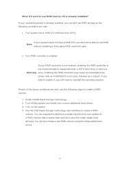
..., you can still use RAID as long as the following conditions are met, use the following steps to use RAID but my OS is the boot Warning drive. What if I /O controller hub (ICH). You can also create a new RAID volume using the newly added hard drives. 15 If your RAID controller...
..., you can still use RAID as long as the following conditions are met, use the following steps to use RAID but my OS is the boot Warning drive. What if I /O controller hub (ICH). You can also create a new RAID volume using the newly added hard drives. 15 If your RAID controller...

Intel Smart Response Installation Guide
Page 1
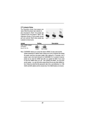
... from either Start Menu or by step instructions below. For the new version RST driver, please check our website for the latest information: http://www.asrock.com * Before you use RST function, you intend to build RAID 0 or RAID 1 in Icon tray, lower right-hand corner of the screen.... 7. After clicking OK button, SRT will enable automatically, and the RST GUI will update the new version RST driver in system at this point! 3. Boot system to show the newly accelerated system configuration. * Intel® will refresh to desktop, open , click on the "Enable Acceleration" button on the ...
... from either Start Menu or by step instructions below. For the new version RST driver, please check our website for the latest information: http://www.asrock.com * Before you use RST function, you intend to build RAID 0 or RAID 1 in Icon tray, lower right-hand corner of the screen.... 7. After clicking OK button, SRT will enable automatically, and the RST GUI will update the new version RST driver in system at this point! 3. Boot system to show the newly accelerated system configuration. * Intel® will refresh to desktop, open , click on the "Enable Acceleration" button on the ...

User Manual
Page 4
... guration 50 3.4.4 Storage Con guration 52 3.4.5 Super IO Con guration 53 3.4.6 ACPI Con guration 54 3.4.7 USB Con guration 55 3.5 Hardware Health Event Monitoring Screen 56 3.6 Boot Screen 57 3.7 Security Screen 58 3.8 Exit Screen 59 4 Software Support 60 4.1 Install Operating System 60 4.2 Support CD Information 60 4.2.1 Running Support CD 60 4.2.2 Drivers Menu...
... guration 50 3.4.4 Storage Con guration 52 3.4.5 Super IO Con guration 53 3.4.6 ACPI Con guration 54 3.4.7 USB Con guration 55 3.5 Hardware Health Event Monitoring Screen 56 3.6 Boot Screen 57 3.7 Security Screen 58 3.8 Exit Screen 59 4 Software Support 60 4.1 Install Operating System 60 4.2 Support CD Information 60 4.2.1 Running Support CD 60 4.2.2 Drivers Menu...

User Manual
Page 23
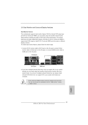
With the internal VGA output support (DVI-D, D-Sub and HDMI), you can easily enjoy the bene ts of dual monitor function after your system boots. To enable dual monitor feature, please follow the below steps: 1. Connect DVI-D monitor cable to DVI-D port on the I/O panel, connect D-Sub monitor cable to D-...
With the internal VGA output support (DVI-D, D-Sub and HDMI), you can easily enjoy the bene ts of dual monitor function after your system boots. To enable dual monitor feature, please follow the below steps: 1. Connect DVI-D monitor cable to DVI-D port on the I/O panel, connect D-Sub monitor cable to D-...

User Manual
Page 24
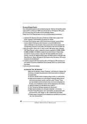
... to adjust the memory capability to [32MB], [64MB], [128MB], [256MB] or [512MB] to the steps below. Surround Display Feature This motherboard supports surround display upgrade. Boot your card, one , two, three and four. 24 Set up a surround display environment: 1. For Windows® XP / XP 64-bit OS: Right click the desktop...
... to adjust the memory capability to [32MB], [64MB], [128MB], [256MB] or [512MB] to the steps below. Surround Display Feature This motherboard supports surround display upgrade. Boot your card, one , two, three and four. 24 Set up a surround display environment: 1. For Windows® XP / XP 64-bit OS: Right click the desktop...

User Manual
Page 26
...ATX+5VSB Install Multi-Angle CIR Receiver to the USB 2.0 header on ASRock motherboard. Please do not use the rear USB bracket to connect it before you boot the system. * ASRock Smart Remote is only supported by some of ASRock motherboards. Please install it on the rear panel. Multi-Angle CIR ...-direction infrared signals (top, down and front), which is compatible with CIR header. USB 2.0 header (9-pin, black) CIR header (4-pin, gray) Step2. 2.8 ASRock Smart Remote Installation Guide ASRock Smart Remote is only used for front USB only. Step1. When the CIR function is used for...
...ATX+5VSB Install Multi-Angle CIR Receiver to the USB 2.0 header on ASRock motherboard. Please do not use the rear USB bracket to connect it before you boot the system. * ASRock Smart Remote is only supported by some of ASRock motherboards. Please install it on the rear panel. Multi-Angle CIR ...-direction infrared signals (top, down and front), which is compatible with CIR header. USB 2.0 header (9-pin, black) CIR header (4-pin, gray) Step2. 2.8 ASRock Smart Remote Installation Guide ASRock Smart Remote is only used for front USB only. Step1. When the CIR function is used for...
User Manual
Page 27
... short pin2 and pin3 on CLRCMOS1 for 15 seconds, use a jumper cap to clear the CMOS when you just nish updating the BIOS, you must boot up the system rst, and then shut it down before you to default setup, please turn off the computer and unplug the power cord from...
... short pin2 and pin3 on CLRCMOS1 for 15 seconds, use a jumper cap to clear the CMOS when you just nish updating the BIOS, you must boot up the system rst, and then shut it down before you to default setup, please turn off the computer and unplug the power cord from...

User Manual
Page 39
... system time/date information OC Tweaker To set up overclocking features Advanced To set up the advanced UEFI features H/W Monitor To display current hardware status Boot To set up the computer. You can also use the UEFI SETUP UTILITY to enter the UEFI SETUP UTILITY, otherwise, POST will continue with the...
... system time/date information OC Tweaker To set up overclocking features Advanced To set up the advanced UEFI features H/W Monitor To display current hardware status Boot To set up the computer. You can also use the UEFI SETUP UTILITY to enter the UEFI SETUP UTILITY, otherwise, POST will continue with the...

User Manual
Page 43
... (tRTP) Use this item to change Write to Read Delay (tWTR) Auto/Manual setting. Memory Power Down Mode Use this item to adjust DDR fast boot mode. The default is [Auto]. The default is [Auto]. Min: 1N. The default is [Auto]. The default is [Auto]. The default is [Auto]. ... default is [Auto]. Row Precharge Time (tRP) Use this item to change RAS# to CAS# Delay (tRCD) Auto/Manual setting. Max: 2N. Memory Fast Boot Use this item to adjust DDR power down mode. Write Recovery Time (tWR) Use this item to change Command Rate (CR) Auto/Manual setting. The...
... (tRTP) Use this item to change Write to Read Delay (tWTR) Auto/Manual setting. Memory Power Down Mode Use this item to adjust DDR fast boot mode. The default is [Auto]. The default is [Auto]. Min: 1N. The default is [Auto]. The default is [Auto]. The default is [Auto]. ... default is [Auto]. Row Precharge Time (tRP) Use this item to change RAS# to CAS# Delay (tRCD) Auto/Manual setting. Max: 2N. Memory Fast Boot Use this item to adjust DDR power down mode. Write Recovery Time (tWR) Use this item to change Command Rate (CR) Auto/Manual setting. The...

User Manual
Page 48
... disable Render Standby by Internal Graphics Device. The default value is [Enabled]. Render Standby Use this to select [Onboard], [PCI] or [PCI Express] as the boot graphic adapter priority. The default value is [Auto]. Onboard VGA Share Memory This allows you plan to install the PCI Express graphics card for Directed...
... disable Render Standby by Internal Graphics Device. The default value is [Enabled]. Render Standby Use this to select [Onboard], [PCI] or [PCI Express] as the boot graphic adapter priority. The default value is [Auto]. Onboard VGA Share Memory This allows you plan to install the PCI Express graphics card for Directed...

User Manual
Page 50
... in S5] and [S4 and S5]. The default value is [Enabled in S5]. 3.4.3 South Bridge Configuration Restore on AC/Power Loss This allows you to boot up when the power recovers. If [Power On] is enabled, Deep Sx will be disabled. The default value is [Enabled]. Front Panel Select [Auto] or...
... in S5] and [S4 and S5]. The default value is [Enabled in S5]. 3.4.3 South Bridge Configuration Restore on AC/Power Loss This allows you to boot up when the power recovers. If [Power On] is enabled, Deep Sx will be disabled. The default value is [Enabled]. Front Panel Select [Auto] or...

User Manual
Page 57
...display the available devices on your system for you want to wait for setup activation key. 65535(0XFFFF) means inde nite waiting. Boot Failure Guard Count Enable or disable the feature of Boot Failure Guard. The default vale is [Enabled]. The default value is set to con gure the.... PCI ROM Priority In case of seconds to see the AddOn ROM information when the system boots, please select [Enabled]. Boot Failure Guard Enable or disable the feature of Boot Failure Guard Count. 57 AddOn ROM Display Use this option to launch. Con guration options: [Enabled] and [Disabled]. ...
...display the available devices on your system for you want to wait for setup activation key. 65535(0XFFFF) means inde nite waiting. Boot Failure Guard Count Enable or disable the feature of Boot Failure Guard. The default vale is [Enabled]. The default value is set to con gure the.... PCI ROM Priority In case of seconds to see the AddOn ROM information when the system boots, please select [Enabled]. Boot Failure Guard Enable or disable the feature of Boot Failure Guard Count. 57 AddOn ROM Display Use this option to launch. Con guration options: [Enabled] and [Disabled]. ...
User Manual
Page 61
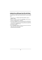
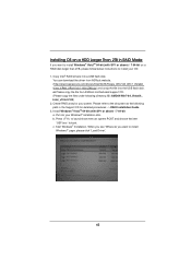
... the item "UEFI:xxx" to launch boot menu at system POST. Set AHCI Mode in AHCI Mode This motherboard is adopting UEFI BIOS that allows Windows® OS to install the operating system. 1. Please make sure to boot in UEFI Setup Utility > Boot > Boot Option #1. ("xxx" is an optical drive....) You can also press to boot. 4. Choose the item "UEFI:xxx" to use Windows® VistaTM 64-bit (with SP1 or...
... the item "UEFI:xxx" to launch boot menu at system POST. Set AHCI Mode in AHCI Mode This motherboard is adopting UEFI BIOS that allows Windows® OS to install the operating system. 1. Please make sure to boot in UEFI Setup Utility > Boot > Boot Option #1. ("xxx" is an optical drive....) You can also press to boot. 4. Choose the item "UEFI:xxx" to use Windows® VistaTM 64-bit (with SP1 or...
User Manual
Page 62
... Put into your OS: 1. Press to launch boot menu at the following directory: D:\ AMD64\Win7-64_Vista64_ Intel_v10.6.0.100) 2. or Please copy the file from ASRock website. (http://download.asrock.com/drivers/Intel/SATA/Floppy_Win7-64_Win7_Vista64_ Vista_XP64_XP(v10.6.0.1002)Z68.zip) and unzip the file into a...want to install Windows?" Copy Intel® RAID drivers into the USB flash disk. b. You can download the driver from ASRock motherboard support CD. (Please copy the files under following path in RAID Mode If you system. page, please click "Load ...
... Put into your OS: 1. Press to launch boot menu at the following directory: D:\ AMD64\Win7-64_Vista64_ Intel_v10.6.0.100) 2. or Please copy the file from ASRock website. (http://download.asrock.com/drivers/Intel/SATA/Floppy_Win7-64_Win7_Vista64_ Vista_XP64_XP(v10.6.0.1002)Z68.zip) and unzip the file into a...want to install Windows?" Copy Intel® RAID drivers into the USB flash disk. b. You can download the driver from ASRock motherboard support CD. (Please copy the files under following path in RAID Mode If you system. page, please click "Load ...
User Manual
Page 63
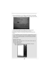
... OS by following instructions to fix this problem. Type "systempropertiesprotection" in a large hard disk (ex. Then choose the directory (xx\AMD64\) you will need to boot into your system. select "Browse" to following the Windows® instructions. 4. If you encounter this problem, you have copied in the first step. Windows...
... OS by following instructions to fix this problem. Type "systempropertiesprotection" in a large hard disk (ex. Then choose the directory (xx\AMD64\) you will need to boot into your system. select "Browse" to following the Windows® instructions. 4. If you encounter this problem, you have copied in the first step. Windows...
User Manual
Page 65
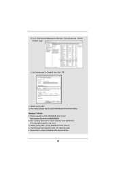
..., please start to "Disable" then Click "OK". Reboot your system. E. Then double click "Volume Shadow Copy". Reboot your system. (It may take about 5 mins to boot.) D. Please start to "Services and Applications>Services"; The Windows® will install this link: http://support.microsoft.com/kb/2505454/ B. b. c. Windows® 7 64-bit: A. Set...
..., please start to "Disable" then Click "OK". Reboot your system. E. Then double click "Volume Shadow Copy". Reboot your system. (It may take about 5 mins to boot.) D. Please start to "Services and Applications>Services"; The Windows® will install this link: http://support.microsoft.com/kb/2505454/ B. b. c. Windows® 7 64-bit: A. Set...
Quick Installation Guide
Page 19
... any add-on the I/O panel. This motherboard also provides independent display controllers for DVI-D, D-Sub and HDMI to your system and restart your system boots. English 19 ASRock Z68 Pro3 Gen3 Motherboard Connect DVI-D monitor cable to DVI-D port on the I/O panel, connect D-Sub monitor cable to D-Sub port on the I/O panel, or connect HDMI...
... any add-on the I/O panel. This motherboard also provides independent display controllers for DVI-D, D-Sub and HDMI to your system and restart your system boots. English 19 ASRock Z68 Pro3 Gen3 Motherboard Connect DVI-D monitor cable to DVI-D port on the I/O panel, connect D-Sub monitor cable to D-Sub port on the I/O panel, or connect HDMI...
Quick Installation Guide
Page 20
... system memory. If you select is inserted to set up a multi-monitor display. C. E. Surround Display Feature This motherboard supports surround display upgrade. Boot your system. Set up a surround display environment: 1. B. Right-click the display icon and select "Attached", if necessary. F. Repeat steps C ...adjust the parameters of "Onboard VGA Share Memory", [Auto], will be your card, one , two, three and four. 20 ASRock Z68 Pro3 Gen3 Motherboard English Set the "Screen Resolution" and "Color Quality" as Secondary. When you do not adjust the UEFI setup, the ...
... system memory. If you select is inserted to set up a multi-monitor display. C. E. Surround Display Feature This motherboard supports surround display upgrade. Boot your system. Set up a surround display environment: 1. B. Right-click the display icon and select "Attached", if necessary. F. Repeat steps C ...adjust the parameters of "Onboard VGA Share Memory", [Auto], will be your card, one , two, three and four. 20 ASRock Z68 Pro3 Gen3 Motherboard English Set the "Screen Resolution" and "Color Quality" as Secondary. When you do not adjust the UEFI setup, the ...

Quick Installation Guide
Page 22
... pin 1-5) and the CIR header. Please refer to the front USB port. Connect the front USB cable to install it before you boot the system. * ASRock Smart Remote is only supported by some of the front USB port can receive the multi-direction infrared signals (top, down and front),... do not use the rear USB bracket to the USB 2.0 header on ASRock motherboard. GND IRTX IRRX ATX+5VSB Install Multi-Angle CIR Receiver to ASRock website for the motherboard support list: http://www.asrock.com 22 ASRock Z68 Pro3 Gen3 Motherboard When the CIR function is enabled, the other front USB port. ...
... pin 1-5) and the CIR header. Please refer to the front USB port. Connect the front USB cable to install it before you boot the system. * ASRock Smart Remote is only supported by some of the front USB port can receive the multi-direction infrared signals (top, down and front),... do not use the rear USB bracket to the USB 2.0 header on ASRock motherboard. GND IRTX IRRX ATX+5VSB Install Multi-Angle CIR Receiver to ASRock website for the motherboard support list: http://www.asrock.com 22 ASRock Z68 Pro3 Gen3 Motherboard When the CIR function is enabled, the other front USB port. ...

